HTR India - Products - Wire Wound Resistors - Silicone Coated Resistors - HFP (English)
•
1 j'aime•8,078 vues

This product is a type of Silicone Coated Resistors, which is a type of Wire Wound Resistors. Features of this product are: Fiber Glass core, PCB pluggable style with different terminations and stand off heights available, UL approved flame retardant coating. This products is consumable for Commercial & industrial electronics. For more information of this product, please copy & paste the url given below: http://htr-india.com/product/hfp/

Recommandé
Recommandé
Contenu connexe
Plus de Creativity Please
Plus de Creativity Please (20)
Dernier
Dernier (20)
HTR India - Products - Wire Wound Resistors - Silicone Coated Resistors - HFP (English)
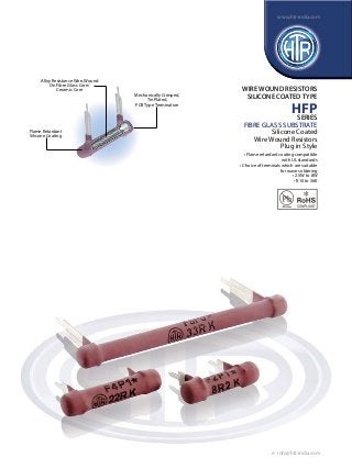
- 1. www.htr-india.com Alloy Resistance Wire, Wound On Fibre Glass Core/ Ceramic Core WIRE WOUND RESISTORS SILICONE COATED TYPE Mechanically Crimped, Tin Plated, PCB Type Termination HFP SERIES FIBRE GLASS SUBSTRATE Silicone Coated Wire Wound Resistors Plug in Style Flame Retardant Silicone Coating • Flame retardant coating compatible with UL standards • Choice of terminals which are suitable for wave soldering • 2.5W to 8W • R10 to 56K e : info@htr-india.com
- 2. www.htr-india.com WIRE WOUND RESISTORS SILICONE COATED TYPE PHYSICAL CONFIGURATION HFP 0 1 CHOICE OF TERMINALS HTR TYPE POWER RATING at 70°C DIMENSIONS (mm) * D RESISTANCE RANGE L +2/-1 ±1 P ±1 TYPICAL TYPICAL WEIGHT PER PC ‘0’ WEIGHT PER PC ‘1’ TERMINAL TERMINAL (gms) (gms) min max F-2P 2.5W 18.2 5.0 10.2 R10 10K 1.38 1.05 F-4P 4W 23.3 5.0 15.2 R10 15K 1.70 1.25 F-5P 5W 33.4 5.0 25.4 R10 27K 2.10 1.90 F-7P 6.5W 43.5 5.0 35.4 R10 39K 2.80 2.50 F-8P 8W 53.7 5.0 45.7 R10 56K 3.10 2.91 • • • * If the longer stand-off terminal is required, suffix the type with ‘0’. For e.g. F-2 P-0 to F-8 P-0. If the shorter stand-off terminal is required, suffix the type with ‘1’. For e.g. F-2 P-1 to F-8 P-1. The resistance range given is applicable to the standard HFP series resistors. Pulse type resistors available. Please consult factory and note (2) in ordering information. For resistance values <1R0, +0.8mm allowed. PHYSICAL CONFIGURATION C CA CZ e : info@htr-india.com
- 3. www.htr-india.com TYPE POWER RATING at 70°C DIMENSIONS (mm) L +2/-1 * D ±1 RESISTANCE RANGE P ±1.0 min max TYPICAL WEIGHT PER PC (gms) ‘C’ terminal ‘CA’ terminal ‘CZ’ terminal F-4P 4W 23.3 5.0 15.2 R10 15K 1.8 2.2 1.8 F-5P 5W 33.4 5.0 25.4 R10 27K 2.2 2.4 2.2 F-7P 6.5W 43.5 5.0 35.4 R10 39K 2.9 3.0 8W 53.7 5.0 45.7 R10 56K 3.15 3.2 HFP 2.8 F-8P WIRE WOUND RESISTORS SILICONE COATED TYPE 3.15 * For resistance values <1R0, +0.8mm allowed CHOICE OF TERMINALS • If the “C” type stand-off terminal is required, suffix the type with “C”. e.g. F-4P-C to F-8P-C • If the “CA” type stand-off terminal is required, suffix the type with “CA”. e.g. F-4P-CA to F-8P-CA • If the “CZ” type stand-off terminal is required, suffix the type with “CZ”. e.g. F-4P-CZ to F-8P-CZ ELECTRICAL AND ENVIRONMENTAL CHARACTERISTICS / DATA PARAMETER/PERFORMANCE TEST & TEST METHOD PERFORMANCE REQUIREMENTS Power Rating (Rated Ambient Temperature) Full Power dissipation at 70°C and linearly derated to zero at 350°C (Refer Derating curve above) Resistance Tolerances Available ±10% (K); ±5% (J) Temperature Range -55°C to +350°C with suitable derating as per derating curve Voltage Rating / Limiting Voltage / Max Working Voltage V= PxR Maximum Overload Voltage Varies depending on resistance value, duration of overload and type of pulse waveform (contact factory for details) Voltage Proof / Dielectric Withstanding Voltage. (based on limiting voltage x 2 for 60 secs) ∆R ± [1% + R05] - No flashover, mechanical damage, arcing or insulation breakdown Short Time Overload (5 x Rated Power for 5 secs) ∆R ± [2% + R05] Temperature Co-efficient of Resistance ± 60 to ±450 ppm/°C (Depending on resistance value) Temperature Cycling (Room Temperature Room Temperature 200°C Room Temperature for 5 cycles) -55°C ∆R ± [2% + R05] Damp Heat (Steady State) (40°C at 93% R.H for 1000 hours - no load applied) ∆R ± [2% + R05] - Average Endurance - Load life (70°C with limiting voltage - 1.5 hours on / 0.5 hours off for 1000 hours) ∆R ± [3% + R05] - Average Solvent Resistance [IPA for 60 secs ± 10 secs] No effect on coating / marking MECHANICAL SPECIFICATIONS PARAMETER/PERFORMANCE TEST & TEST METHOD PERFORMANCE REQUIREMENTS Terminal Tensile Strength 40 Newtons Resistance to Soldering Heat (260°C - 270°C for 10 secs) ∆R ± [0.2% + R05] - Typical Solderability (As per IEC - 60068 - 2 - 20Ta) Must meet the requirements laid down Marking As per IEC Pub. 60062 TEMPERATURE RISE 1. Body Temperature Measuring Point 2. Solder Joint Temperature Measuring Point e : info@htr-india.com
- 4. www.htr-india.com Temperature At Full Power Dissipation TYPE Measuring Point 2 Measuring Point 1 High Resistance Range Low Resistance Range ‘O’ Type Terminal ‘1’ Type Terminal ‘C’ Type Terminal ‘CA’ Type Terminal ‘CZ’ Type Terminal F2P 2300C 1800C 500C 700C F4P 2850C 2350C 530C 980C 550C 520C 2850C 2400C 500C 850C 570C 570C 580C F7P 292 C 260 C 0 45 C 0 85 C 0 62 C 0 55 C 550C F8P 290 C 246 C 55 C 80 C 57 C 55 C HFP 490C F5P WIRE WOUND RESISTORS SILICONE COATED TYPE 550C 0 0 0 0 0 0 0 0 TYPICAL APPLICATIONS The HFP series was evolved in order to provide a low cost but reliable alternative to those OEM’s who have automated assembly facilities including wave soldering. Due to their design, these resistors have merely to be plugged into the PCB and wave soldered. ORDERING INFORMATION Series Type Packing Resistance Value Tolerance Type of Termination HFP F8P / F8P* Bulk F8P / F8P* 100R J 0 / 1 / C / CA / CZ Note: In this series, there is a choice of terminal stand-off heights available; please refer “PHYSICAL CONFIGURATION” for selection. 1. For RoHS version - F8P * 2. For Pulse type - F8P I e : info@htr-india.com