Low Rate Call Girls in Laxmi Nagar Delhi Call 9990771857
Uml types
1. Article-stack.com UML
What is UML Collaboration Diagrams?
Use a collaboration diagram (collaboration diagram: An interaction diagram that shows, for one system event described by one use
case, how a group of objects collaborate with one another.) to show relationships among object roles such as the set of messages
exchanged among the objects to achieve an operation or result.
UML Collaboration diagrams (interaction diagrams) illustrate the relationship and interaction between software objects. They require
use cases, system operation contracts, and domain model to already exist. The collaboration diagram illustrates messages being sent
between classes and objects (instances). A diagram is created for each system operation that relates to the current development
cycle (iteration).
When creating collaboration diagrams, patterns are used to justify relationships. Patterns are best principles for assigning
responsibilities to objects and are described further in the section on patterns. There are two main types of patterns used for
assigning responsibilities which are evaluative patterns and driving patterns.
Each system operation initiates a collaboration diagram. Therefore, there is a collaboration diagram for every system operation.
Who can use them and how?
Software developers: Represent software applications using the Unified Modeling Language (UML) notation.
Software developers: Illustrate and interpret software application relationships, actions, and connections.
Program managers: Show high-level static software structures in presentations and specification documentation.
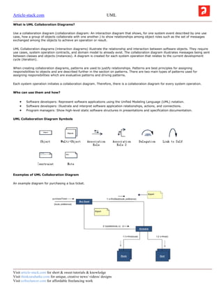
UML Collaboration Diagram Symbols
Examples of UML Collaboration Diagram
An example diagram for purchasing a bus ticket.
Visit article-stack.com for short & sweet tutorials & knowledge
Visit thinkzarahatke.com for unique, creative news/ videos/ designs
Visit ezfreelancer.com for affordable freelancing work
2. Article-stack.com UML
What is UML Component Diagrams?
Use a component diagram (component diagram: An implementation diagram that shows the structure of the code itself. From a
component diagram, you can learn about compiler and run-time dependencies between software components, such as source code
files or DLLs.) to partition a system into cohesive components and show the structure of the code itself.
Who can use them and how?
Software developers: Represent software applications using the Unified Modeling Language (UML) notation.
Software developers: Illustrate and interpret software application relationships, actions, and connections.
Program managers: Show high-level static software structures in presentations and specification documentation.
UML Component Diagram Symbols
EDraw is ideal software to draw UML component diagrams.
Examples of UML Component Diagram
What is UML Static Structure Diagrams?
Use static structure diagrams (static structure diagram: A diagram that shows the static structure of a model; that is, the elements
that exist (such as classes and types), the internal structure of the elements, and their relationships to one another.) to create
conceptual diagrams that represent concepts from the real world and the relationships between them, or class diagrams that
decompose a software system into its parts.
Visit article-stack.com for short & sweet tutorials & knowledge
Visit thinkzarahatke.com for unique, creative news/ videos/ designs
Visit ezfreelancer.com for affordable freelancing work
3. Article-stack.com UML
Who can use them and how?
Software developers: Represent software applications using the Unified Modeling Language (UML) notation.
Software developers: Illustrate and interpret software application relationships, actions, and connections.
Program managers: Show high-level static software structures in presentations and specification documentation.
UML Static Structure Symbols
EDraw is ideal software to draw UML static structure diagrams.
What is UML Deployment Diagram?
Use a deployment diagram (deployment diagram: An implementation diagram that shows the structure of a run-time system. From
it, you can learn about the physical relationships among software and hardware components and the distribution of components to
processing nodes.) to show the structure of the run-time system and communicate how the hardware and software elements that
make up an application will be configured and deployed.
Who can use them and how?
Software developers: Represent software applications using the Unified Modeling Language (UML) notation.
Software developers: Illustrate and interpret software application relationships, actions, and connections.
Program managers: Show high-level static software structures in presentations and specification documentation.
UML Deployment Symbols
Visit article-stack.com for short & sweet tutorials & knowledge
Visit thinkzarahatke.com for unique, creative news/ videos/ designs
Visit ezfreelancer.com for affordable freelancing work
4. Article-stack.com UML
Visit article-stack.com for short & sweet tutorials & knowledge
Visit thinkzarahatke.com for unique, creative news/ videos/ designs
Visit ezfreelancer.com for affordable freelancing work