Contenu connexe
Similaire à S123 b30u (20)
Plus de Domotica daVinci (20)
S123 b30u
- 1. Restricted Use – UK Trials S1xxR-Series Instructions
Horstmann Group Ltd ©2009 Page 1 of 32 Pxxxxx Issue 1.0
All Rights Reserved 2December2009
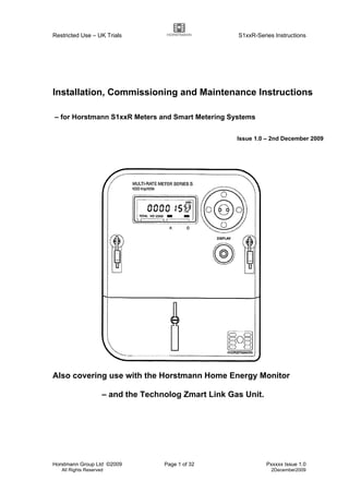
Installation, Commissioning and Maintenance Instructions
– for Horstmann S1xxR Meters and Smart Metering Systems
Issue 1.0 – 2nd December 2009
Also covering use with the Horstmann Home Energy Monitor
– and the Technolog Zmart Link Gas Unit.
- 2. Restricted Use – UK Trials S1xxR-Series Instructions
Horstmann Group Ltd ©2009 Page 2 of 32 Pxxxxx Issue 1.0
All Rights Reserved 2December2009
List of Changes for S1xxR Installation Instructions
1. Document created based on “Installation and Commissioning Instructions SG23R”
Issue 1 .1.
Version Edited Date Checked Issued
Issue 1.0 MW 2Dec09 BL 2Dec09
- 3. Restricted Use – UK Trials S1xxR-Series Instructions
Horstmann Group Ltd ©2009 Page 3 of 32 Pxxxxx Issue 1.0
All Rights Reserved 2December2009
Contents
Part 1 – Introduction
1. Background
2. Equipment and Tariff Configurations
3. Safety Considerations
Part 2 – Installation
4. Assessment of the Metering Site
5. Selection of GSM Network and SIM Card
6. Selection of Tariff Configuration
7. Installation of the Metering Equipment
Part 3 – Commissioning
8. Initial Commissioning of the S1xxR Meter in Installer Mode
9. Commissioning an S1xxR Metering Installation
10. Customer Instruction
Part 4 – Maintenance and Servicing
11. Post-Installation Servicing
12. Change of Home Energy Monitor
13. Change of Gas Meter or Zmart Link
14. Removal of Metering Equipment
ANNEXES
A. Configuration Diagrams for S1xxR-Series Meters
B. Meter Display Sequences
C. Home Energy Monitor Displays
D. Overview of the Home Energy Monitor
E. Signal Strength Survey for S1xxR Meters
F. Advanced Functions for Z-Wave Certified Meter
- 4. Restricted Use – UK Trials S1xxR-Series Instructions
Horstmann Group Ltd ©2009 Page 4 of 32 Pxxxxx Issue 1.0
All Rights Reserved 2December2009
Part 1 - Introduction
1. Background
Caution – Restricted Use: These Instructions for the S1xxR meters and any associated
smart metering equipment are only intended for use by Accredited Electricity Meter
Operators and Registered Gas Meter Workers, operating under the requisite industry
agreements and practices and regulations. The equipment is not intended for installation
and commissioning by any other persons, and Horstmann will not be responsible for the
consequences of any such use or attempted use or misuse of these products and
instructions.
S1xxR is the type designation for a range of Z-Wave S-series single element electricity
meters that run on a 230V 50Hz mains supply, and the xx denotes a hardware
configuration for whether the meter also carries a 100 Amp and/or a 2 Amp switch. The
S123R is a full hardware specification S-series Z-Wave meter, and has the full part number
S123xxxR, where the additional xxx define the customer configuration such as tariff
scheme and a customer identifier. The Z-Wave user functionality and the schedule of Z-
Wave message transmissions are identical for all S1xxR meters, and neither the 100 A or
2 A switch is Z-Wave controlled.
The Horstmann S1xxR Smart Meters form part of a smart metering system that can
provide residential customers with detailed energy data for electricity and gas usage. The
S1xxR can support the Zmart Link gas mini-logger (on a suitable U6/R5 metric or Imperial
gas meter) for collecting Gas consumption, and the Horstmann Home Energy Monitor
(HEM) for displaying Electricity and Gas consumption. The products may be used to study
how various methods of providing better information to residential customers about their
recent energy consumption can give rise to better understanding of energy usage and
longer-term reductions in energy consumption.
The S1xxR range of meters is based on the following general assumptions:
a) All meters will be for residential single-phase two-wire electricity supplies, for import
of energy only (the HEM does not support export of energy).
b) No prepayment-metered customers will be involved.
c) No two-meter electric heating tariffs will be involved.
d) All gas meters involved will be U6/R5 compatible metric or Imperial meters;
(1 pulse per 0.01 m3
, or 1 pulse per cu ft).
e) All electricity meters from the factory will be delivered with a basic “default” single-
rate tariff configuration (SSC 393).
f) Multi-rate tariff configurations may be loaded via local opto port.
g) The HEMs are delivered without any site-specific parameters loaded. The HEM picks
up the tariff structure and times from the associated electricity meter. The electricity
(and gas) prices/rates are to be set on the HEM during (or prior to) the installation
visit.
The gas meter reading on the HEM includes an allowance for the initial offset reading
when a new Zmart Link unit is installed.
- 5. Restricted Use – UK Trials S1xxR-Series Instructions
Horstmann Group Ltd ©2009 Page 5 of 32 Pxxxxx Issue 1.0
All Rights Reserved 2December2009
2. Equipment and Tariff Configurations
These are the S1xxR meters available:
S100xxxR: 100 Amp metered only
S111xxxR: 100 Amp metered with 100 Amp Contactor
S114xxxR: 100 Amp metered with 2 Amp Relay
S115xxxR: 100 Amp metered with 2 Amp Relay (Volt Free)
S116xxxR: 100 Amp metered with 2 Amp Relay (1200 VA)
S117xxxR: 100 Amp metered with 2 Amp Relay (1200 VA & Volt Free)
S122xxxR: 100 Amp metered with 100 Amp Contactor & 2 Amp Relay
S123xxxR: 100 Amp metered with 100 Amp Contactor & 2 Amp Relay (Volt Free)
Configuration A = Electricity Meter Only.
Configuration B = Electricity Meter and Gas.
Configuration C = Electricity Meter and Monitor Only.
Configuration D = Electricity Meter, Gas and Monitor.
See Annex A for diagrammatic representations.
For S1xxR meters configurations A and B are of no use to the customer, unless a product
from another OEM is used to request electricity and gas from the meter.
All meters can support tariffs of up to 4 rates.
3. Safety Considerations
These Instructions for the S1xxR meters and any associated smart metering equipment
are only intended for use by Accredited Electricity Meter Operators and Registered Gas
Meter Workers, operating under the requisite industry agreements and practices and
regulations.
The equipment is not intended for installation and commissioning by any other persons,
and Horstmann will not be responsible for the consequences of any such use or attempted
use or misuse of these products and instructions.
The relevant electrical safety regulations and practices must be followed at all stages of
installation and commissioning and subsequent maintenance visits.
Where applicable the relevant gas safety regulations and practices must also be followed
at all stages of installation and commissioning and subsequent maintenance visits.
The equipment is not designed or intended for user servicing or repairs. Where a unit is
shown to be faulty it should be returned to Horstmann for service or repair and re-
certification.
Part 2 - Installation
4. Assessment of the Metering Site
Prior to the visit the following site information is to be determined, including the gas-related
information for sites involving the S1xxR meter:
- 6. Restricted Use – UK Trials S1xxR-Series Instructions
Horstmann Group Ltd ©2009 Page 6 of 32 Pxxxxx Issue 1.0
All Rights Reserved 2December2009
- Site address and MPAN (and MPRN).
- Supplier and electricity tariff type (and SSC), and Configuration.
- Electricity (and gas) tariff prices/rates, after discounts, with/without VAT (for the HEM).
- Any electricity load switching requirements.
- Arrangements for change of existing gas meter (including from semi-concealed type).
On arrival at a site involving the S1xxR meter a short survey is also needed to ensure that
satisfactory wireless operation at 868 MHz can be achieved for each of the two radio
paths: Meter to HEM, and Meter to Zmart Link (if dual-fuel). See Annex E for details.
The results of this short survey will indicate whether it is likely to be practicable for the
installation of the HEM to proceed (also for the Zmart Link gas unit on dual-fuel sites).
5. Selection of GSM Network and SIM Card
Not Applicable.
6. Selection of Tariff Configuration
The following tariff programmes may be programmed into the meters at the meter test
station or depot. The SSC references include those that have traditionally been used.
a) General/Standard Tariff – single-rate – SSC 393.
Normal Rate 1 operates continuously.
b) Economy 7 – 2-rate – SSC 244.
Low Rate 2 from 00.00 to 07.00 GMT-only, all days; switches A and D are closed.
Normal Rate 1 at all other times.
Note: other E7 times and split time blocks may arise (SSCs 151, 153, 373, 378).
c) Economy 10 – 2-rate – SSC 935.
Low Rate 2 from 00.00 to 05.00, 13.00 to 16.00, 20.00 to 22.00, GMT-only, all days.
Normal Rate 1 at all other times.
d) TOU Trials Tariff – 4-rate example
Peak Rate 4 from 16.00 to 19.30, Monday to Friday only, 1 Nov to 1 Mar, GMT/BST.
Evening Rate 3 from 19.30 to 24.00, all days.
Night Rate 2 from 00.00 to 07.30, all days.
Day Rate 1 at all other times.
Details of the suggested arrangements and tariff configurations are given in Annex A.
7. Installation of the Metering Equipment
Installation of S1xxR Smart Meters
The accredited Meter Operator will replace the customer’s existing electricity meter by the
selected meter in accordance with the relevant regulations and codes of practice. Annex A
gives an indication of the various arrangements that are expected to be found, but the
installation is the responsibility of the appointed metering services organisation.
- 7. Restricted Use – UK Trials S1xxR-Series Instructions
Horstmann Group Ltd ©2009 Page 7 of 32 Pxxxxx Issue 1.0
All Rights Reserved 2December2009
Note: Economy 7 sites are unlikely to involve gas supplies and metering, so only
configurations A and C are then applicable. Load switching via the 100 A switched output
may be used on some E7 sites (using terminal 5 on suitable meters).
Installation of the Home Energy Monitor
For installations where a HEM is involved (configurations C and D) the HEM may initially
be plugged into a convenient 13 A socket near the electricity meter and made ready for
commissioning – see Section 9.1.
Where an installation with gas but no HEM is involved (Configuration B) then a temporary
“test” HEM may initially be plugged into a convenient 13 A socket near the electricity meter
and made ready for commissioning – see Section 9.1. This is used to check the
commissioning of the Zmart Link gas unit; then the test HEM is deleted from the meter
wireless network (in Installer mode) and removed from site.
After commissioning has progressed for configurations C and D (see section 9.3) the HEM
should be installed in an appropriate permanent location (section 9.5) and the customer
instructed in its use (section 10).
Installation of the Gas Meter and Zmart Link Unit
Where gas metering is also involved (configurations B and D) the accredited Meter Worker
will usually replace the customer’s existing gas meter by a U6/R5 compatible metric or
Imperial gas meter in accordance with the relevant regulations and codes of practice.
Annex A gives an indication of the various arrangements that are expected to be found, but
the installation is the responsibility of the appointed metering services organisation.
The Zmart Link unit will be connected to the gas meter’s R5 pulse output during the
commissioning process, and only after this can it be fixed in a secure manner near to the
gas meter - see section 9.3(c) and Annex E2.
Part 3 - Commissioning
8. Initial Commissioning of the S1xxR Meter in Installer Mode
Initial checks and powering up are similar to those for a normal multi-rate credit meter.
On power up the S1xxR meter enters Installer Mode for the first 5 minutes – see Annex B
for operation and the Installer display list. Note: Learn Mode and Protocol Reset may also
need to be added to the display list for some Zwave network configurations – see Annex F.
The meter starts up in the Load Switch Exercise mode. If the blue button is held down for 2
seconds it switches to the Installer Display List. Each time the button is held down for 2
seconds the meter alternates between these two facilities, until the 5-minute Installer Mode
period expires.
- 8. Restricted Use – UK Trials S1xxR-Series Instructions
Horstmann Group Ltd ©2009 Page 8 of 32 Pxxxxx Issue 1.0
All Rights Reserved 2December2009
Use the Installer Display List check that the meter is showing the correct registers, time,
date, and tariff reference. With the meter the Installer List includes up to 5 extra items at
the end for Zwave network operation – these are used where a Zmart Link unit and/or
HEM are installed (see 9.2 and 9.3).
Note: With Economy 7 tariffs the 100 A switched output may be used on some sites
(switch D out via terminal 5 on suitable meters). Use the Load Switch Exercise facility to
check that switch D is switching the heating circuit – in this mode each short press of the
button changes the state of switch D and then A, as shown by the 2 icon bars along the
lower edge of the meter display. Wait for 6 seconds between each press in this mode.
If the meter display flashes “all 8’s” every 5-seconds then the meter should be returned to
the meter test station.
For an S1xxR meter with a HEM and/or Zmart Link gas unit then go to 9.1, 9.2, and 9.3.
9. Commissioning of an S1xxR Meter Installation
9.1 General
Assumptions for using this section:
– An S1xxR electricity meter with appropriate tariff configuration has already been
selected and installed and prepared for commissioning as in 7 and 8 above.
– A U6/R5 metric gas meter has been installed and is ready for use (for Configuration B
or D).
– A Zmart Link gas unit is also available (initially held at the electricity meter position).
– A HEM is available and initially plugged into a convenient 13 A socket (for
Configuration C or D). A temporary Test HEM is used for Configuration B – see 7.2.
Also for S1xxR sites a short survey has already been completed successfully to assess
wireless operation at 868 MHz for each radio path – the meter to HEM location, and meter
to Zmart Link location if a dual-fuel site. See 4 above and Annex E, then decide how to
proceed with the installation.
This section deals with the various equipment configurations:
Configuration A – Go straight to 9.4.
Configuration B – Go to 9.2 (Test HEM), then 9.3, then 9.4.
Configuration C – Go to 9.2 then 9.4 then 9.5.
Configuration D – Go to 9.2 then 9.3 then 9.4 then 9.5.
The certified electricity meter is capable of including any z-wave compliant unit to its
network. The procedure for the meter to include any device follows the inclusion procedure
detailed in section 9.2 or 9.3.
The certified electricity meter is capable of excluding any z-wave compliant unit from its
network. The procedure for the meter to exclude any device follows the exclusion
procedure detailed in section 12.2 or 13.2.
The certified electricity meter can become part of another z-wave compliant network, and
be removed from it through use of the Learn Mode selection detailed in Annex F.
- 9. Restricted Use – UK Trials S1xxR-Series Instructions
Horstmann Group Ltd ©2009 Page 9 of 32 Pxxxxx Issue 1.0
All Rights Reserved 2December2009
9.2 Adding a Home Energy Monitor (HEM)
(with configurations C and D, or as a temporary Test HEM with configuration B).
HEM – Include Process
a) Preparation
The HEM may be plugged into a 13 A socket near the meter initially, if this is more
convenient than its final position (see also 7.2 and Annex E2).
The meter should now be powered up so it is in Installer Mode for the first 5 minutes.
The HEM should be ready for inclusion in the meter’s Zwave network (flap open).
b) Inclusion
The HEM can be included to any z-wave compliant network, but for the purposes of this
document the meter is the z-wave controller. Put the meter into network include mode as
follows:
1. Press and hold the blue front button for 2 seconds (enters Installer Displays).
2. Cycle through each display menu item with single presses until the display
shows “INC NODE”. Do not press the blue button again unless repeating the
process.
3. Wait 5 seconds and the display will show “oooo” for one second.
4. Display will now show either “SENT” or “FAIL” (if “FAIL” wait for 30 seconds and
retry the process from the second bullet - the routing circuit was busy). Note: If it
is still not possible to obtain the “SENT” message then the meter should be
powered down briefly and powered up again – then wait for 2 minutes before
repeating the inclusion process.
5. The Zwave module is now in the INCLUDE state for the next 2 minutes.
The procedure on the HEM to join any z-wave compliant network (assuming a controller is
present in include mode, and in this case is the meter) is:
1. Press the green button on the HEM (i.e. under the flap).
2. Choose the menu item “COMMISSIONING”, using the Plus and Minus buttons
and press the Enter button.
3. Choose the menu item “NETWORK SUPPORT” and press the Enter button.
4. Choose the menu item “SEND FRAME” and press the Enter button.
5. The HEM will display “JOINED NETWORK” (Pass) or “NO CHANGE” (i.e.
failure or HEM is already included, wait and repeat).
6. In the case of a successful include press the green button to return to the main
display. Close the flap.
7. In the case of a fail, if the HEM is not already included repeat the procedure
from step 2, but ensure the controller is in include mode.
During the process the meter display should briefly show the message “PASS INC” in
which case the procedure is complete, else the meter will display “FAIL” in which case wait
for a 30 seconds period to elapse and repeat this process from the second bullet point (still
within the 5-minute installer mode period). Note: It is important to step around the 15 steps
in the Installer Display sequence to arrive back at the “INC NODE” display to re-activate
the INCLUDE state if a repeat attempt is needed.
Before moving the HEM to a final position for the customer (in section 9.5 below) and while
the meter and HEM are still powered up check that the HEM is operating properly. As the
meter sends the reports supported by the HEM, immediately after inclusion, check that the
main display on the HEM shows the correct time and date (in GMT/BST clock time), and
- 10. Restricted Use – UK Trials S1xxR-Series Instructions
Horstmann Group Ltd ©2009 Page 10 of 32 Pxxxxx Issue 1.0
All Rights Reserved 2December2009
that a Power Now update occurs every 15 seconds. If the HEM was commissioned in its
final position then carry out this check now.
c) Completion
If the S1xxR installation also includes a Zmart Link gas unit fitted to a U6/R5 metric gas
meter, then that unit should next be included on to the electricity meter’s Zwave
network, the Zmart Link completion checks should also be made, and the GAS
OFFSET value should be entered into the HEM – all as described in 9.3 below.
If the electricity rates (prices) and the gas rate have not been entered earlier or prior to
the visit, then set the electricity rate(s) and any gas rate now – see Annex C Figures 2
and 3 and Annex D. The settings may be checked from the main screen by pressing
the blank pushbutton. N.B: These settings may be input at any convenient time.
When the HEM is set up ready for use it can be unplugged and moved to the chosen
location suitable for the customer, typically in the kitchen, hall, or lounge (see 9.5).
Satisfactory wireless reception at the new location should be checked by observing the
15-second updates to the Power Now indication on the HEM’s main display.
Finally, the customer should be given a brief overview and instructions on the use of
the HEM (see section 10).
9.3 Adding a Zmart Link Gas Unit
(with configurations B and D)
a) Preparation for Zmart Link Include Process
A U6/R5 metric gas meter is already installed and ready for use.
The HEM has already been commissioned (see 9.2) as it is used for some of the
completion checks below. The HEM may initially be plugged into a convenient 13 A
socket near the meter for this work, before moving it to its final location – see Annex
E3. It may be a temporary Test HEM for configuration B.
The Zmart Link gas unit should be held near to the electricity meter for the Include
process.
The meter should now be powered up so it is in Installer Mode for the first 5 minutes.
The Zmart Link unit should be ready for inclusion in the meter’s Zwave network (a
magnet should be at hand to initiate the Zmart Link unit).
b) Inclusion (Zmart Link is held close to S1xxR meter)
The ZMART can be included to any z-wave compliant network, but for the purposes of this
document the meter is the z-wave controller. Put the meter into network include mode as
follows:
1. Press and hold the blue front button for 2 seconds (enters Installer Displays).
2. Cycle through each display menu item with single presses until the display
shows “INC NODE”. Do not press the blue button again unless repeating the
process.
3. Wait 5 seconds and the display will show “oooo” for one second.
4. Display will now show either “SENT” or “FAIL” (if “FAIL” wait for 30 seconds and
retry the process from the second bullet).
5. The Zwave module is now in the INCLUDE state for the next 2 minutes.
The procedure on the ZMART to join any z-wave compliant network (assuming a controller
is present in include mode, and in this case is the meter) is:
1. Swipe the unit’s front panel with a magnet once, a blue LED should flash, if no
flash is seen swipe again.
- 11. Restricted Use – UK Trials S1xxR-Series Instructions
Horstmann Group Ltd ©2009 Page 11 of 32 Pxxxxx Issue 1.0
All Rights Reserved 2December2009
Note: The Zmart Link’s internal total register will start incrementing from 0 at this point.
The meter display should briefly show the message “PASS INC” in which case the Include
process is complete, else the meter will display “FAIL” in which case wait 30 seconds and
repeat this process from the second bullet point (still within the 5-minute installer mode
period). Note: It is important to step around the 15 steps in the Installer Display sequence
to arrive back at the “INC NODE” display to re-activate the INCLUDE state in the meter.
If it was not possible to obtain PASS in this last step then exclude the Zmart Link (see
13.2b) and start this inclusion process again.
c) Completion
After completing the Include process the Zmart Link unit should be taken to the gas
meter, connected to the R5 interface, and fixed in position securely – see Annex E2.
The current reading of the gas meter (at the time that the new Zmart Link unit was
connected) should also be noted, in addition to what may be required under gas
metering procedures and MAMCOP – see 9.4.
If a HEM is also included as part of the smart metering installation (and has been set
for a metric or Imperial gas meter, as appropriate), then set the HEM’s GAS OFFSET
value to the initial 5-digit reading of the gas meter index (in whole m3
or x 100 cu ft), i.e.
the reading at the time that the new Zmart Link unit was connected to the gas meter.
Refer to (d) below. This setting may also be done later, i.e. after the S1xxR’s installer
mode period has expired.
It could be 30 minutes or so before the next automatic gas data transfer will be
discernible on the HEM [under GAS – ENERGY – Gas Used]. Instead check the
wireless communications with the Zmart Link in its installed position by swiping a
MAGNET over the front face of the Zmart Link (the Zmart’s BLUE LED should flash).
Then go to the HEM and check that the Gas Used screen [Total at Time and Date] has
then updated successfully – it is necessary to re-select via [GAS – ENERGY – Gas
Used] to refresh the HEM display. If some gas use is taking place it should be possible
to see a small increase in the Gas Used Total (00000.00 m3
reading) on the HEM.
This gas data check may be done with the HEM either in an initial temporary position,
or in its final location. It should also be done where a Test HEM is used (configuration
B); after this delete the Test HEM from the S1xxR meter and remove it (see 13.2b).
d) Setting the GAS OFFSET Value on the HEM (if a Zmart Link gas unit is included)
(HEM) Press the green button on the HEM (i.e. under the flap).
(HEM) Choose the menu item “COMMISSIONING”, using the Plus and Minus buttons
and press the Enter button.
(HEM) Choose the menu item “GAS OFFSET VALUE” and press the Enter button.
(HEM) Input the gas offset value using the Plus, Minus and Enter buttons (one digit at a
time). This is the initial 5-digit reading of the gas meter index (in whole m3
or x 100 cu
ft), at the time that a new Zmart Link unit is connected to the gas meter.
(HEM) Press the green button to return to the main display. Close the flap.
9.4 Meter Data Retrieval Commissioning Process
Not Applicable.
- 12. Restricted Use – UK Trials S1xxR-Series Instructions
Horstmann Group Ltd ©2009 Page 12 of 32 Pxxxxx Issue 1.0
All Rights Reserved 2December2009
Notes:
1. Any Test HEM may be disconnected now.
2. The meter operator completes the job record.
9.5 Finding an Appropriate Location for the HEM in the Home
If the HEM was initially commissioned in a temporary position it should now be moved to its
final position (preferred by the customer as far as possible). The location for the HEM
should already have been chosen to give satisfactory radio reception as in 4 and Annex E3
– this should normally be within 6 m (20 feet) of the electricity meter position where
transmission through building walls is involved. Check that the Power Now value shown on
the main display is normally updated from the meter every 15 s. Poor reception is shown
after 2 or more minutes by the NO COMMS indication appearing on the main display – see
10.. Also check that the main display on the HEM shows the correct time and date (in
GMT/BST clock time), and that the correct number of rates for the tariff in the S1xxR meter
are shown on the HEM’s Energy used Today screen [Normal = Rate 1]. In normal
operation the two red/orange/green consumption indicators light when the HEM is showing
the main display; red does not mean the HEM is faulty – see Annex D.
In addition to ensuring that satisfactory radio reception is achieved the following practical
points need to be considered when selecting a suitable location for the Home Energy
Monitor, as covered in the initial short survey of the premises in section 4 and Annex E3:
Indoors only, in a frequently used place (lounge, hall, kitchen…).
Near to a suitable 13 A socket (the HEM cable is 1.1 m long).
On a work surface (not at low level – keep away from small children).
Where it is easily accessible frequently, but is unlikely to be dislodged or dropped.
Away from pouring water or steam – taps, sinks, kettles.
Not likely to be in direct sunlight for lengthy periods.
Not close to strong sources of heat.
Not covered up at all, nor in a cupboard or drawer.
Not on vibrating equipment (washing machines, spin dryers, microwave ovens).
The unit must remain plugged into the (dedicated) 13 A socket at all times – the red
notice on the plug confirming this should be pointed out to the customer as part of the
customer instructions given in 10 below.
10. Customer Instruction
For the S1xxR meter alone (configuration A) or the S1xxR meter with only the Zmart Link
gas unit included (configuration B) there is little customer instruction required during the
installation visit. Once the meter has been powered up for longer than the installer display
mode (5 minutes) then the first press of the meter’s pushbutton results in the present
instantaneous power being displayed in Watts (e.g. P 000405 is 405 Watts), and this
facility may help some users discover and respond to some aspects of their electricity
usage.
- 13. Restricted Use – UK Trials S1xxR-Series Instructions
Horstmann Group Ltd ©2009 Page 13 of 32 Pxxxxx Issue 1.0
All Rights Reserved 2December2009
When the HEM is used with the S1xxR meter (in configurations C or D) then this
instantaneous power value is still available on the meter. The same value is transferred to
the HEM every 15 s and drives the power bar on the main HEM “Power Now” screen. The
HEM’s “Power Now” screen includes the minimum and maximum values of instantaneous
power that have occurred since last midnight, and the size of the minimum value is very
important for energy saving. For instance if the minimum daily power does not usually fall
below 0.10 kW or 100 Watts then this indicates that there are some devices always in use
that over one year would draw power equivalent to approximately 25% of average
domestic electricity consumption (400 W average or 3600 kWh per year). The user should
be advised to look into the nature of their minimum load (or “leakage”) regularly and seek
to reduce it. See Annexes C and D for operation of the HEM.
When the HEM is commissioned it will only show the “Power Now” kilowatt value initially,
and the daily, weekly, and 28-day period screens on the display will show zero data. Over
the next few hours and days the usage data for the displays will gradually build up, and
after 28 days nearly all the displays will be populated. This encourages a continuous
process of discovery by the energy users, but also means that only limited instruction can
be given to the users at the time of installation. The user should be made aware of this
characteristic and encouraged to look at the additional screens regularly. There are
numerous additional screens for electricity and gas usage - the cost indications of energy
consumed (using the £ buttons) are also likely to be useful for most customers as data
builds up, once the energy rates (prices) have been set.
The unit must remain plugged into the chosen (dedicated) 13 A socket at all times – the
red notice on the plug confirming this should be pointed out to the customer.
The “Power Now” updates on the main screen should be pointed out to the customer,
noting that if this changes to “NO COMMS” persistently then the energy supplier should be
informed. See the figure below.
Finally, the customer should be made aware that the HEM only works in conjunction with
the electricity meter installed in their premises, and will not work if taken to another home.
Part 4 – Maintenance and Servicing
11. Post-Installation Servicing
There are no regular maintenance requirements during normal operation and use for the
S1xxR meters, Zmart Link gas unit, and HEM. However the price settings in the HEM will
21:10 Saturday 11 August
Elec Gas
ENERGY
£ £
ENERGY
No Comms = - -.- - kW (00.06- 07.44)
ENERGY
£
EXIT
No Communications Received for Past 3 Minutes
- 14. Restricted Use – UK Trials S1xxR-Series Instructions
Horstmann Group Ltd ©2009 Page 14 of 32 Pxxxxx Issue 1.0
All Rights Reserved 2December2009
require changing if the electricity and/or gas prices change see Annex C Figure 3 and
Annex D – this may be carried out by the customer with the User Guide.
The S1xxR meter, Zmart Link gas unit, and HEM all include internal lithium batteries that
are sufficient to cover the life of the unit in normal operation.
None of the equipment is designed or intended for user servicing or repairs. None of the
units should be dismantled and then returned to use. Where a unit is shown to be faulty it
should be returned to Horstmann for service or repair and any re-certification.
Fault-finding methods will be established partly from experience with the equipment.
Procedures for changing a HEM or Zmart Link gas unit are given in 12 and 13 below.
12. Change of Home Energy Monitor
12.1 General
(Configuration C) If the HEM has to be replaced for any reason then follow the
Exclude process below, and then add a new HEM as in section 9. If the existing HEM
has failed and cannot be excluded from the Zwave network (e.g. its internal power
supply has failed) then it is permissible to take the faulty HEM away and include a new
second HEM onto the Zwave network.
(Configuration D) The HEM may be replaced in the same way as above, but since a
Zmart Link unit is also included as part of the installation then it may not be
straightforward to establish what the gas offset value for the new HEM with existing
Zmart Link unit should now be (apart from using trial and error). The relevant gas offset
reading will have been set in the old HEM - but may no longer be accessible.
In this situation the existing Zmart Link unit should rather be replaced by a new Zmart
Link unit; then the new HEM should be included as in section 9. New energy data in
the HEM will then gradually be built up. The new GAS OFFSET value in the HEM
should be set to the gas meter reading at the date/time of change to the new Zmart
Link unit - see Section 9. The current reading of the gas meter should be recorded, in
addition to what may be required under gas metering procedures and MAMCOP – see
9.4.
12.2 HEM – Exclude Process
a) Preparation
The existing HEM should be plugged into a 13 A socket near the meter, if this is more
convenient.
The meter should now be powered up so it is in Installer Mode for the first 5 minutes.
The HEM should be ready for exclusion from the meter’s Zwave network (flap open).
b) Exclusion
The HEM can be excluded from any z-wave compliant network, but for the purposes of
this document the meter is the z-wave controller. Put the meter into network exclude
mode as follows:
1. Press and hold the blue front button for 2 seconds (enters Installer Displays).
- 15. Restricted Use – UK Trials S1xxR-Series Instructions
Horstmann Group Ltd ©2009 Page 15 of 32 Pxxxxx Issue 1.0
All Rights Reserved 2December2009
2. Cycle through each display menu item with single presses until the display shows
“DEL NODE”. Do not press the blue button again unless repeating the process.
3. Wait 5 seconds and the display will show “oooo” for one second.
4. Display will now show either “SENT” or “FAIL” (if “FAIL” wait 30 seconds and retry
the process from the second bullet - the routing circuit was busy).
5. The meter’s Zwave module is now in the EXCLUDE state for the next 2 minutes.
The procedure on the HEM to leave any z-wave compliant network (assuming a controller
is present in exclude mode, and in this case is the meter) is:
1. Press the green button on the HEM (i.e. under the flap).
2. Choose the menu item “COMMISSIONING”, using the Plus and Minus buttons and
press the Enter button.
3. Choose the menu item “NETWORK SUPPORT” and press the Enter button.
4. Choose the menu item “SEND FRAME” and press the Enter button.
5. The HEM will display “LEFT NETWORK” (Pass) or “NO CHANGE” (i.e. failure or
HEM is already excluded).
6. Press the green button to return to the main display. Close the flap.
During the process the meter display should briefly show the message “PASS DEL” in
which case the procedure is complete, else the meter will display “FAIL” in which case wait
30 seconds and repeat this process from the second bullet point (still within the 5-minute
installer mode period).
c) Completion
Either the old HEM unit is to be removed permanently, or a replacement HEM unit is
now to be fitted. A replacement HEM may normally be fitted without changing the
electricity meter or the Zmart Link gas unit (if fitted).
If a replacement HEM unit is now to be fitted, follow the “HEM – Include Process” at
section 9 above. The replacement HEM will gradually build up new stored energy data
over the coming days, weeks, and 28-day period.
Note 1: If the existing HEM has failed and cannot be excluded from the Z-wave network
(e.g. its internal power supply has failed) then it is permissible to take the faulty HEM
away and include a new second HEM onto the Zwave network.
Note 2: If an excluded HEM is subsequently included into the Zwave network of a meter
then its internal stored data for the past 28 days energy usage will be reset to zeroes.
New energy data for the metering installation that the HEM is now included in will
gradually be built up.
Note 3: If there appears to be a permanent difficulty with logging HEM units and/or Zmart
Link units on or off the electricity meter’s Zwave network then it may be necessary to
change out the meter as well as the other Zwave units to recover normal operation. In
this case the new units will need to be included onto the Zwave network of the new
electricity meter and new energy data in the HEM will gradually be built up. The GAS
OFFSET value should be entered into the new HEM based on the current reading on
the existing gas meter. This will involve carrying out the overall Installation and
Commissioning processes again.
13. Change of Gas Meter or Zmart Link
- 16. Restricted Use – UK Trials S1xxR-Series Instructions
Horstmann Group Ltd ©2009 Page 16 of 32 Pxxxxx Issue 1.0
All Rights Reserved 2December2009
13.1 Change of Gas Meter
(Configuration B) If the gas meter has to be replaced for any reason then the existing
Zmart Link unit may be connected to the new gas meter. The current readings of the
old and new gas meters and the date/time of the meter change should also then be
recorded, in addition to what may be required under gas metering procedures and
MAMCOP – see 9.4. This assumes that no HEM is involved (configuration B only).
(Configuration D) If a HEM is also included as part of the installation then it will not be
straightforward to establish what the gas offset value for the existing HEM plus Zmart
Link unit should now be (apart from using trial and error). In this situation the existing
Zmart Link unit should rather be replaced by a new Zmart Link unit; the HEM should be
excluded and then included again. New energy data in the HEM will then gradually be
built up. The new GAS OFFSET value in the HEM should be set to the new gas meter
reading at the date/time of change to the new Zmart Link unit - see 9. The current
reading of the old and new gas meters and the date/time of change of the replacement
Zmart Link unit should also be recorded, in addition to what may be required under gas
metering procedures and MAMCOP – see 9.4.
If the gas meter is to remain but the Zmart Link unit is to be replaced then refer to
section 13.2 below.
13.2 Change of Zmart Link Unit
Zmart Link - Exclude Process
a) Preparation
Before carrying out the Exclusion process the Zmart Link unit should be disconnected
from the R5 interface, removed from the gas meter position, and taken to the electricity
meter position.
The Zmart Link gas unit should be held near to the electricity meter for the Exclude
process.
The meter should now be powered up so it is in Installer Mode for the first 5 minutes.
The Zmart Link unit should be ready for Exclusion from the meter’s Zwave network (a
magnet should be at hand to initiate the Zmart Link unit).
b) Exclusion
The ZMART can be excluded from any z-wave compliant network, but for the purposes
of this document the meter is the z-wave controller. Put the meter into network exclude
mode as follows:
1. Press and hold the front button for 2 seconds (enters Installer Displays).
2. Cycle through each display menu item with single presses until the display shows
“DEL NODE”. Do not press the blue button again unless repeating the process.
3. Wait 5 seconds and the display will show “oooo” for one second.
4. Display will now show either “SENT” or “FAIL” (if “FAIL” wait 30 seconds and retry
the process from the second bullet - the routing circuit was busy).
5. The Zwave module is now in the EXCLUDE state for the next 2 minutes.
The procedure on the ZMART to leave any z-wave compliant network (assuming a
controller is present in exclude mode, and in this case is the meter) is:
- 17. Restricted Use – UK Trials S1xxR-Series Instructions
Horstmann Group Ltd ©2009 Page 17 of 32 Pxxxxx Issue 1.0
All Rights Reserved 2December2009
1. Swipe the front panel with a magnet once, a blue LED should flash, if no flash is
seen swipe again.
The meter display should briefly show the message “PASS DEL” in which case the
procedure is complete, else the meter will display “FAIL” in which case wait 30 seconds
and repeat this process from the second bullet point.
c) Completion
Either the old Zmart Link unit is to be removed permanently, or a replacement Zmart
Link unit is now to be fitted. In the first case the current reading of the gas meter should
also be recorded, in addition to what may be required under gas metering procedures
and MAMCOP.
If a replacement Zmart Link unit is now to be fitted (configurations B or D), follow the
“Zmart Link - Include Process” as in Section 9 above. It is recommended that a new
Zmart Link unit is used as the replacement, not an already-used-and-excluded unit. For
configuration B the use of a temporary Test HEM is relevant – see 7.4 and 9.3.
The current reading of the gas meter and the date/time of change of the replacement
Zmart Link unit should be noted, in addition to what may be required under gas
metering procedures and MAMCOP.
If the installation also includes a HEM (configuration D) it is recommended that the
HEM should be excluded and then included again during the change of the Zmart Link
unit. This will reset the HEMs internal storage of energy usage data to zeroes,
preventing confusion arising from old and new Zmart Link gas data. New energy data
for the smart metering installation that the HEM is now included in will gradually be built
up. Set the GAS OFFSET value in the HEM to the gas meter reading at the date/time
of change of the replacement Zmart Link unit - see 9.
Note 1: If an already-used-and-since-excluded Zmart Link unit is subsequently included
into the Zwave network of an electricity meter (configuration B) then it will output the
new gas usage data to the electricity meter, which will continue to record new half-hour
data into its gas recording channel. The current reading of the gas meter and the
date/time of change of the replacement Zmart Link unit should also be noted, in
addition to what may be required under gas metering procedures and MAMCOP.
Note 2: If under Note 1 above an existing HEM is also in use (configuration D) it will not
be straightforward to establish what the gas offset value for the HEM should now be
(apart from using trial and error). In such situations a failed Zmart Link unit should
rather be replaced by a new Zmart Link unit; the HEM should be excluded and then
included again. In this case new energy data in the HEM will gradually be built up. Set
the GAS OFFSET value in the HEM to the gas meter reading at the date/time of
change of the replacement Zmart Link unit - see section 9.3(d).
Note 3: If there appears to be a permanent difficulty with logging Zmart Link units and/or
HEM units on or off the electricity meter’s Zwave network then it may be necessary to
change out the electricity meter as well as the other units to recover normal operation.
In this case new energy data in the new HEM will gradually be built up.
14. Removal of Metering Equipment
Where the smart metering equipment is permanently removed from a premises (e.g. due to
Change of Supplier) then notification of the site and meters involved and the date of
removal should be recorded.
- 18. Restricted Use – UK Trials S1xxR-Series Instructions
Horstmann Group Ltd ©2009 Page 18 of 32 Pxxxxx Issue 1.0
All Rights Reserved 2December2009
- 19. Restricted Use – UK Trials S1xxR-Series Instructions
Horstmann Group Ltd ©2009 Page 19 of 32 Pxxxxx Issue 1.0
All Rights Reserved 2December2009
ANNEX A – Configuration Diagrams for S1xxR-Series Meters
Note: Meters below are shown with both switches fitted = S123R
S1xxR BL 2Dec09
S1xxR Meter – no Switched Load (A1)
1 2 3 4 5
RATE
I
NOW
02345
kWh
CUT-OUT
TO HOUSEHOLD CIRCUIT
NEUTRAL CIRCUIT
INCOMING
MAINS
For the Standard Tariff (Single-Rate):
- No load switching - Terminal 5 is bunged.
For the Two-Rate E10 Tariff:
- Rate Registers 1 and 2 are Normal and Low.
- 3 On/Off Times per Day, 7 Days, GMT-only (SSC 935).
- 20.00 – 24.00, 02.00 – 05.00, 14.00 – 16.00 GMT.
- No Load Switching by Meter – Terminal 5 is bunged.
D (100 A)
PB
A B
RF
Controller
kWh
METER
A
(2 A)
N
T
S1xxR BL 2Dec09
S1xxR Meter – with Switched Load (A2)
CUT-OUT
TO HOUSEHOLD CIRCUIT
TO HEATING CIRCUIT(S)
NEUTRAL CIRCUITS
INCOMING
MAINS
For the Domestic Economy 7h Tariff:
- Switch D is used for Heating Loads..
- Rate Registers 1 and 2 are Normal and Low.
- Switching Times are 00.00-07.00, 7 days, GMT (SSC 244).
NB:
- Other E7 times may be needed; SSC 153, 01.00 – 08.00h.
- There may also be some split block E7 tariffs, (SSC 373).
1 2 3 4 5
RATE
I
NOW
02345
kWh
D (100 A)
PB
A B
RF
Controller
kWh
METER
A
(2 A)
N
T
- 20. Restricted Use – UK Trials S1xxR-Series Instructions
Horstmann Group Ltd ©2009 Page 20 of 32 Pxxxxx Issue 1.0
All Rights Reserved 2December2009
S1xxR BL 2Dec09
S1xxR Meter – with Gas Meter (B)
1 2 3 4 5
RATE
I
NOW
02345
kWh
CUT-OUT
TO HOUSEHOLD CIRCUIT
NEUTRAL CIRCUIT
INCOMING
MAINS
For the Standard Tariff (Single-Rate):
- No load switching - Terminal 5 is bunged. SSC 393.
D (100 A)
PB
A B
RF
Controller
kWh
METER
A
(2 A)
N
T
12345 m3
U6/R5 Gas Meter
Zmart
Link
S1xxR Meter
S1xxR BL 2Dec09
S1xxR Meter – no Switched Load (C1)
1 2 3 4 5
RATE
I
NOW
02345
kWh
CUT-OUT
TO HOUSEHOLD CIRCUIT
NEUTRAL CIRCUIT
INCOMING
MAINS
For the Standard Tariff (Single-Rate):
- No load switching - Terminal 5 is bunged.
- Rate 1 is Normal on HEM. SSC 393.
For the Two-Rate E10 Tariff:
- Rate Registers 1 and 2 are Normal and Low on HEM.
- 3 On/Off Times per Day, 7 Days, GMT-only (SSC 935).
- 00.00 – 05.00, 13.00 – 16.00, 20.00 – 22.00 GMT.
- No Load Switching by Meter – Terminal 5 is bunged.
D (100 A)
PB
A B
RF
Controller
kWh
METER
A
(2 A)
N
T
S1xxR Meter
21:10 Saturday 11 August
Evening Rate for 2h 50mins
Elec Gas
ENERGY
£ £
ENERGY
Power Now = 01.15kW (00.06 - 07.44)
ENERGY
£
EXIT
RATES
21:10 Saturday 11 August
Evening Rate for 2h 50mins
Elec Gas
ENERGY
£ £
ENERGY
Power Now = 01.15kW (00.06 - 07.44)
ENERGY
£
EXIT
RATES
Home Energy Monitor (HEM)
13 A
PLUG
- 21. Restricted Use – UK Trials S1xxR-Series Instructions
Horstmann Group Ltd ©2009 Page 21 of 32 Pxxxxx Issue 1.0
All Rights Reserved 2December2009
S1xxR BL 2Dec09
S1xxR Meter – with Switched Load (C2)
CUT-OUT
TO HOUSEHOLD CIRCUIT
TO HEATING CIRCUIT(S)
NEUTRAL CIRCUITS
INCOMING
MAINS
For the Domestic Economy 7h Tariff:
- Switch D is used for Heating Loads..
- Rate Registers 1 and 2 are Normal and Low on HEM.
- Switching Times are 00.00-07.00, 7 days, GMT (SSC 244).
NB:
- Other E7 times may be needed; 01.00 – 08.00 (SSC 153).
- There may also be some split block E7 tariffs (SSC 373).
1 2 3 4 5
RATE
I
NOW
02345
kWh
D (100 A)
PB
A B
RF
Controller
kWh
METER
A
(2 A)
N
T
21:10 Saturday 11 August
Evening Rate for 2h 50mins
Elec Gas
ENERGY
£ £
ENERGY
Power Now = 01.15kW (00.06 - 07.44)
ENERGY
£
EXIT
RATES
21:10 Saturday 11 August
Evening Rate for 2h 50mins
Elec Gas
ENERGY
£ £
ENERGY
Power Now = 01.15kW (00.06 - 07.44)
ENERGY
£
EXIT
RATES
Home Energy Monitor (HEM)
13 A
PLUG
S1xxR Meter
S1xxR BL 2Dec09
S1xxR Meter – with HEM and Gas Meter (D)
1 2 3 4 5
RATE
I
NOW
02345
kWh
CUT-OUT
TO HOUSEHOLD CIRCUIT
NEUTRAL CIRCUIT
INCOMING
MAINS
No Electric Heating in these Premises.
For the Standard Tariff (Single-Rate):
- No load switching - Terminal 5 is bunged.
- Rate 1 is Normal on HEM. SSC 393 GMT.
D (100 A)
PB
A B
RF
Controller
kWh
METER
A
(2 A)
N
T
S1xxR Meter
21:10 Saturday 11 August
Evening Rate for 2h 50mins
Elec Gas
ENERGY
£ £
ENERGY
Power Now = 01.15kW (00.06 - 07.44)
ENERGY
£
EXIT
RATES
21:10 Saturday 11 August
Evening Rate for 2h 50mins
Elec Gas
ENERGY
£ £
ENERGY
Power Now = 01.15kW (00.06 - 07.44)
ENERGY
£
EXIT
RATES
Home Energy Monitor (HEM)
13 A
PLUG
12345 m3
U6/R5 Gas Meter
Zmart
Link
- 22. Restricted Use – UK Trials S1xxR-Series Instructions
Horstmann Group Ltd ©2009 Page 22 of 32 Pxxxxx Issue 1.0
All Rights Reserved 2December2009
ANNEX B - Meter Display Sequences
Installer Mode and Normal Mode (Installer Mode is 5 minutes for S1xxR):
S1xxR Displays BL
2Dec09
Meter Power Up : into Installer Mode for First 5 Minutes:
a) Load Switch Exercise Mode – Switches D and A
b) Installer Display List – with additional functionality for Z-wave
Note: Hold button down for 2 to 5 s to alternate between (a) and (b)
After First 5 Minutes : Meter is in Normal Mode:
a) Normal Display List applies – push to step through list
b) After Time-out of 1 Minute it reverts to “RATE NOW” display
c) No other pushbutton action available in Normal Mode
S1xxR Displays BL
2Dec09
2
Display Representation
Current Register RATE NOW kWh
Watts P 000750
Display Test [All segments]
Time TIME
Date DATE
Rate 1 RATE (NOW) kWh
Rate 2 RATE (NOW) kWh
Rate 3 RATE (NOW) kWh
Rate 4 RATE (NOW) kWh
Import Total TOTAL kWh
Export Total TOTAL←← kWh
Tariff Reference rEF 393
Tariff Change Date t
Zwave Include Inc nodE
Zwave Exclude dEL nodE
Zwave NIF nEt
‹ End of List ›
- 23. Restricted Use – UK Trials S1xxR-Series Instructions
Horstmann Group Ltd ©2009 Page 23 of 32 Pxxxxx Issue 1.0
All Rights Reserved 2December2009
S1xxR Displays BL
2Dec09
INSTALLER List
Current Register
Display Test
Time
Date
Rate 1
Rate 2
Rate 3
Rate 4
Import Total
Export Total
Tariff Reference
Tariff Change Date
Zwave Include
Zwave Exclude
Zwave nEt
‹ End of List ›
NORMAL List – 1R
Current Register
Watts
Display Test
Time
Date
Rate 1
Tariff Reference
‹ End of List ›
NORMAL List – 2R
Current Register
Watts
Display Test
Time
Date
Rate 1
Rate 2
Import Total
Tariff Reference
‹ End of List ›
NORMAL List – 4R
Current Register
Watts
Display Test
Time
Date
Rate 1
Rate 2
Rate 3
Rate 4
Import Total
Tariff Reference
‹ End of List ›
Display Sequences for S1xxR Meters (with Z-wave)-
- 24. Restricted Use – UK Trials S1xxR-Series Instructions
Horstmann Group Ltd ©2009 Page 24 of 32 Pxxxxx Issue 1.0
All Rights Reserved 2December2009
ANNEX C – Home Energy Monitor Displays
(See Annex D for an Overview of the HEM)
HEM Main BL
7Sep07
1
Home Energy Monitor – Main Display
21:10 Saturday 11 August
Evening Rate for 2h 50mins
Elec Gas
ENERGY
£ £
ENERGY
Power Now = 01.15kW (00.06 - 07.44)
ENERGY
£
EXIT
Electricity and Gas Rates, p/kWh “SET” button behind flap
To this
Main
Display
HEM Main BL
7Sep07
2
Home Energy Monitor – Setting Mode
SET ELECTRICITY
SET GAS
COMMISSIONING
SYSTEM DEFAULTS
ENERGY
£ £
ENERGY ENERGY
£
EXIT
SET
ENTERPLUS
MINUS
- Flap Hinged Down -
Press
“SET”
button
once to
enter,
again to
complete
or leave
Setting
Mode
Up/down
menu list
or
adjust digits,
then ENTER
- 25. Restricted Use – UK Trials S1xxR-Series Instructions
Horstmann Group Ltd ©2009 Page 25 of 32 Pxxxxx Issue 1.0
All Rights Reserved 2December2009
3
ELECTRICITY TARIFFS
SET RATE 1
SET RATE 2
SET RATE 3
SET RATE 4
ELECTRICITY TARIFF – RATE 1
For 1, 2, 3 and 4 rate meters
PENCE PER KWH:
09.5
SET ELECTRICITY
SET GAS
COMMISSIONING
SYSTEM DEFAULTS
ENTER
ENTER
SET
[MAIN SCREEN]
SET
Select using
Plus/Minus
Select using
Plus/Minus
Adjust using
Plus/Minus
[Repeat for Rate 2 etc if used]
[Repeat for Gas Tariff if used]
(Rate 1 is Normal Rate)
SETTING THE ELECTRICITY AND GAS PRICES (pence/kWh)
GAS TARIFF
Single Rate Only
PENCE PER KWH:
02.5
SET
4
COMMISSIONING THE HEM
SET ELECTRICITY
SET GAS
COMMISSIONING
SYSTEM DEFAULTS
COMMISSIONING
NETWORK SUPPORT
GAS OFFSET VALUE
RATE 1 ASSIGNMENT
NETWORK SUPPORT
SEND FRAME
NETWORK SUPPORT
NO CHANGE
GAS OFFSET VALUE
0 0 0 0 0 units (m3)
RATE 1 ASSIGNMENT
LOW
HIGH
NETWORK SUPPORT
JOINED NETWORKOR
- 26. Restricted Use – UK Trials S1xxR-Series Instructions
Horstmann Group Ltd ©2009 Page 26 of 32 Pxxxxx Issue 1.0
All Rights Reserved 2December2009
6
SELECTING THE ELECTRICITY DISPLAY MODE
21:10 Saturday 11 August
Evening Rate for 2h 50mins
Elec Gas
ENERGY
£ £
ENERGY
Power Now = 01.15kW (00.06 - 07.44)
ENERGY
£
EXIT
21:10 Saturday 11 August
Evening Rate for 2h 50mins
Elec Gas
ENERGY
£ £
ENERGY
Power Now = 01.15kW (00.06 - 07.44)
ENERGY
£
EXIT
Electricity Used
Total = 23789 kWh
AT 21.30 SAT 11 AUG
Daily Weekly Period Exit
Electricity used Today
Day Rate 1 = 2.7 kWh
Night Rate 2 = 5.6 kWh
Evening Rate 3 = 0.0 kWh
Peak Rate 4 = 0.0 kWh
Daily Weekly Period Exit
Electricity used Yesterday
Day Rate 1 = 4.7 kWh
Night Rate 2 = 9.6 kWh
Evening Rate 3 = 0.0 kWh
Peak Rate 4 = 0.0 kWh
Daily Weekly Period Exit
Electricity Values
Today so far £0.51
Yesterday total £0.83
Daily Weekly Period Exit
£
£
ENERGY
ENERGY
ENERGY
ENERGY
Electricity Values - Weekly
Electricity Values – 28 Day Period
££
More
X
SELECTING THE GAS DISPLAY MODE – If Gas Metering is Included
21:10 Saturday 11 August
Evening Rate for 2h 50mins
Elec Gas
ENERGY
£ £
ENERGY
Power Now = 01.15kW (00.06 - 07.44)
ENERGY
£
EXIT
21:10 Saturday 11 August
Evening Rate for 2h 50mins
Elec Gas
ENERGY
£ £
ENERGY
Power Now = 01.15kW (00.06 - 07.44)
ENERGY
£
EXIT
Gas Values
Today so far £0.51
Yesterday total £0.83
Daily Weekly Period Exit
£ENERGY
ENERGY
ENERGY
Gas Values - Weekly
Gas Values – 28 Day Period
££
X
Gas Data
Total = 01234.56 units(m3
)
AT 21.30 SAT 11 AUG
Daily Weekly Period Exit
Today Wkday Wkend
Daily Weekly Exit
Typical Gas Use
Period
24
Today Wkday Wkend
Daily Weekly Exit
Typical Gas Use
Period
24
Daily Weekly Exit
Gas Usage Last 2 Days
Period
6
Daily Weekly Exit
Gas Usage Last 2 Days
Period
6
To other
displays
- 27. Restricted Use – UK Trials S1xxR-Series Instructions
Horstmann Group Ltd ©2009 Page 27 of 32 Pxxxxx Issue 1.0
All Rights Reserved 2December2009
Electricity Values – Weekly
This Week so far £1.51
Last Week total £2.83
Daily Weekly Period Exit
Electricity Values – 28 Day Period
This Period so far £0.51
Last Period total £0.83
Daily Weekly Period Exit
Electricity - Weekly
This Week so far 002.0kWh
Last Week total 016.0kWh
Daily Weekly Period Exit
Electricity – 28 Day Period
Period so far 0138kWh
Last Period 0187kWh
Daily Weekly Period Exit
Electricity used Today
Normal Rate 1 = 2.7 kWh
Low Rate 2 = 5.6 kWh
Daily Weekly Period Exit
Electricity used Yesterday
Normal Rate 1 = 4.7 kWh
Low Rate 2 = 9.6 kWh
Daily Weekly Period Exit
EXAMPLES OF ELECTRICITY AND GAS TEXT DISPLAYS
Gas - Weekly
This Week so far 054.0 units
Last Week total 085.0 units
Daily Weekly Period Exit
Gas – 28 Day Period
Period so far 0140 units
Last Period 0185 units
Daily Weekly Period Exit
Gas Values – Weekly
This Week so far £1.51
Last Week total £2.83
Daily Weekly Period Exit
Gas Values – 28 Day Period
This Period so far £0.51
Last Period total £0.83
Daily Weekly Period Exit
Gas Data
Total = 00000.00 units(m3
)
TIME STAMP NOT AVAILABLE
Daily Weekly Period Exit
If no gas unit is fitted, or no
communication with gas unit
8
Today Wkday Wkend
Daily Weekly Exit
Typical Electricity Use
Period
24
Today Wkday Wkend
Daily Weekly Exit
Typical Gas Use
Period
24
Today Wkday Wkend
Daily Weekly Exit
Typical Gas Use
Period
24
Daily Weekly Exit
Gas Usage Last 2 Days
Period
6
Daily Weekly Exit
Gas Usage Last 2 Days
Period
6
Daily Weekly Exit
Electricity Usage Last 2 Days
Period
3
Daily Weekly Exit
Electricity Usage Last 2 Days
Period
3
Daily Weekly Exit
Electricity Usage Last 28 Days
Period
12
Daily Weekly Exit
Electricity Usage Last 28 Days
Period
12
Daily Weekly Exit
Gas Usage Last 28 Days
Period
24
Daily Weekly Exit
Gas Usage Last 28 Days
Period
24
Daily Weekly Exit
Electricity Usage – Last 2 Weeks
Period
12
Daily Weekly Exit
Electricity Usage – Last 2 Weeks
Period
12
Daily Weekly Exit
Gas Usage – Last 2 Weeks
Period
12
Daily Weekly Exit
Gas Usage – Last 2 Weeks
Period
12
EXAMPLES OF ELECTRICITY AND GAS CHART DISPLAYS
- 28. Restricted Use – UK Trials S1xxR-Series Instructions
Horstmann Group Ltd ©2009 Page 28 of 32 Pxxxxx Issue 1.0
All Rights Reserved 2December2009
ANNEX D – Overview of the Home Energy Monitor
The HEM is used with configurations C and D. The HEM is plugged into a 13 A socket in a
convenient location (e.g. kitchen, hall, lounge) and should remain plugged in at all times
after commissioning – a red notice to this effect is included on the plug cover. The HEM
should be placed in a location where it can regularly be seen, but will not get in the way of
daily activities. If the HEM has to be unplugged or repositioned for any reason it should
only be unplugged for short periods of time (a few minutes). The HEM is provided with a
mains cable 1.1 m long.
The HEM must be included into the S1xxR meter’s local Z-wave network during
commissioning. Where gas data is also to be available on the HEM the Zmart Link unit
must also be included into the S1xxR’s network.
The HEMs are delivered without any site-specific parameters loaded. The HEM picks up
the tariff structure and times from the associated S1xxR meter. The electricity (and gas)
prices/rates are to be set on the HEM during the installation visit. The maximum price
setting for the electricity and gas rates is 25.5 p/kWh, in increments of 0.1 p/kWh. The rate
names Normal/Low are displayed on the HEM if the meter has a 1-rate or 2-rate tariff
configuration, while any 3- or 4-rate tariff in the meter results in the rate names Day, Night,
Evening, and Peak being displayed on the HEM. Annex C gives display examples.
The HEM uses the prices/rates set into it to calculate the cost of the energy used over the
previous and current day, week, and rolling 28-day period. The energy values are stored in
the HEM and when their £ values are requested they are calculated from the prices/rates
that are currently set in the HEM. Changing the price settings means that the new
prices/rates will be used on the stored energy values when new £ values are requested
and they will be displayed for the recent days, weeks, and the rolling 28-day period. The
HEM does not allow for standing changes or block-type tariffs when indicating the £ values
of the various energy values consumed. The £ values indicated are shown on the same
basis as the price/rate settings that are entered – so this may be with or without any dual-
fuel discount, with or without any direct debit discount, and with or without 5% VAT on
domestic energy supplies. (The prices printed on customers’ bills are often expressed
WITH any dual-fuel discount, WITHOUT any direct debit discount, and WITHOUT 5% VAT
added).
In normal operation the two red/orange/green consumption indicators light when the HEM
is showing its main display, according to the following rules (the left indicator is for
electricity, the other is for gas usage):
- Green: Today’s usage so far is less than 90% of yesterday's (or yesterday was zero).
- Amber: Today’s usage so far is between 90% and 110% of yesterday's consumption.
- Red: Today’s usage so far is above 110% of yesterday's consumption.
The indicators may show any of these colours – red does not mean the HEM is faulty.
If the HEM has not received any meter data for 3 minutes then "NO COMMS" is shown on
the main screen instead of "Power Now" – this reverts to normal (Power Now) as soon as a
successful 15-second update is received from the meter. The wireless transmissions to the
HEM are at a very low power level (a milliwatt).
- 29. Restricted Use – UK Trials S1xxR-Series Instructions
Horstmann Group Ltd ©2009 Page 29 of 32 Pxxxxx Issue 1.0
All Rights Reserved 2December2009
ANNEX E – Signal Strength Survey for S1xxR Meters
E1 General
When a home is to have an S1xxR meter installed along with a HEM Energy Monitor
and/or a Zmart Link gas unit then a short survey is first needed to ensure that satisfactory
wireless operation at 868 MHz can be achieved for each of the two radio paths: S1xxR to
HEM, and S1xxR to Zmart Link. If the survey results are acceptable then installation of the
smart metering equipment can go ahead as in chapters 7 to 9 of the instructions.
The basic method uses an SG23R or S1xxR battery-powered test transmitter and a hand
held RF signal strength meter, operating at 868 MHz. The test transmitter is temporarily
placed or fixed close to the electricity meter position and switched on, then the RF signal
strength meter is taken to the gas meter position and/or the place proposed for the HEM
Energy Monitor to check for adequate signal strength at each of those locations.
E2 Checking the Gas Meter Location
For Configurations B and D where the gas meter is to be fitted with a Zmart Link gas unit
then the potential location area for the Zmart Link unit is also effectively predetermined.
Although the Zmart Link is fitted with a 2 m cable for connection to the gas meter pulse
output, in domestic premises it is unlikely that the unit (with its internal antenna) can be
located much more than 30 cm away from the gas meter, for various practical reasons.
This may limit the scope for finding a location with sufficient signal strength for the Zmart
Link unit in some premises.
Check the RF signal strength by taking the RF meter to the gas meter location, which will
involve one of the four types of layout in (a) to (d) below. The RF meter is held vertically at
arm’s length in each potential fitting location and the signal strength noted as acceptable or
not for the Zmart – 3 or 4 amber LEDs should be lit. The potential positions for fixing the
Zmart Link near conventional gas meters are:
a) External gas meter cabinet, surface mounted: Velcro to upper left or right sidewall.
b) External gas meter cabinet, flush mounted: Velcro to upper left rear wall, or hang from
flexible inlet pipe.
c) Internal wall-mounted gas meter location, higher up: hang from flexible inlet pipe.
d) Internal floor-mounted gas meter location: fix to gas pipe 30 cm above meter if
practical.
Evaluation of results: There may be some premises where the electricity meter and gas
meter positions are either too far apart for successful wireless operation or the path
between them involves several walls or a thick external stone wall or an external corner.
Large white goods in the direct path may also reduce signal coverage. Where the gas
meter is on a solid concrete floor it may not be practical to mount the Zmart Link unit (with
its internal antenna) at an adequate height for good communications. In such cases the
signal strength near the gas meter may not be sufficient and a decision will need to be
taken to exclude the Zmart Link and gas data from this installation.
Note 1: The Zmart Link gas unit itself is not intended for outdoor use without an enclosure.
Note 2: Use of the Zmart Link with semi-concealed gas meters is not anticipated.
- 30. Restricted Use – UK Trials S1xxR-Series Instructions
Horstmann Group Ltd ©2009 Page 30 of 32 Pxxxxx Issue 1.0
All Rights Reserved 2December2009
E3 Checking the HEM Energy Monitor Location
For Configurations C and D where a HEM is to be installed then a permanent indoor
location (convenient for the customer) must be found and checked for sufficient signal
strength – using the SG23R or S1xxR test transmitter at the electricity meter position. It
may also simplify the commissioning process if a temporary location for the HEM that is
convenient for the meter operator can first be found and checked – e.g. where the S1xxR
meter is installed in a garage the HEM might also be used temporarily in the garage for
commissioning, then moved to the permanent location for the final checks.
For Configuration B (with Zmart Link gas but no HEM permanently installed) a temporary
location for a “Test” HEM that is convenient for the meter operator should also be found
and checked (e.g. a socket near an indoor electricity meter, or in the hall or utility room).
The permanent location for the HEM must be chosen to give satisfactory signal reception –
this should normally be within 6 m (20 feet) horizontally and 4 m (13 feet) vertically of the
electricity meter position. Where a property has thick stone walls and the electricity meter
is in an outdoor meter box any possible HEM locations are likely to be found on the inside
near to the electricity meter position.
In addition to ensuring that satisfactory signal reception is obtained the following practical
points need to be considered when selecting a suitable permanent location for the Home
Energy Monitor:
On a desk or work surface (not at low level – keep away from small children).
Where it is easily accessible frequently, but is unlikely to be dislodged or dropped.
Away from pouring water or steam – taps, sinks, kettles.
Not likely to be in direct sunlight for lengthy periods or close to strong sources of heat.
Not covered up at all, nor in a cupboard or drawer…
Not on vibrating equipment (washing machines, spin dryers, microwave ovens).
The HEM must be able to remain plugged into its own 13 A socket at all times.
Check the potential HEM location(s) by taking the RF meter to them and measure the RF
signal strength with the SG23R or S1xxR test transmitter in position and switched on; both
the permanent and the temporary locations should be checked in turn. The RF meter is
held vertically at arm’s length at each potential location and the signal strength then noted
as acceptable or not for the HEM – all 4 amber LEDs should be lit in suitable locations.
Evaluation of results: Try to avoid choosing a location for the HEM where users must place
themselves between the unit and the electricity meter when operating the HEM – the RF
meter may give varying results in such situations. Also try to avoid locations where thick
solid walls and large white goods are in the direct line between the electricity meter and the
HEM. There may be limited or no scope for finding a practical location with sufficient signal
strength for the HEM in some premises. In this case the HEM should not remain on site,
but if the Zmart Link gas unit has been installed satisfactorily then the site may be left
logging gas and electricity data after excluding the HEM and removing it from the
premises.
- 31. Restricted Use – UK Trials S1xxR-Series Instructions
Horstmann Group Ltd ©2009 Page 31 of 32 Pxxxxx Issue 1.0
All Rights Reserved 2December2009
ANNEX F – Advanced Functions for Z-Wave Certified Meter
This section is for advanced use of z-wave functions only, such as installing the system on
another Z-wave network within the property.
F1 – Learn Mode
With the meter in installer mode the following procedure needs to be carried out with the
third party controller in network include mode to add the meter to its network.
With the meter in installer mode the following procedure needs to be carried out with the
third party controller in network exclude mode to remove the meter from its network.
1. Press and hold the blue button for 2 seconds (enters Installer Displays).
2. Cycle through each menu display item with single presses until the display shows
“LEArn”. Do not press the blue button again unless repeating the process.
3. Wait 10s and the display will show “oooo” for one second.
4. Display will now show either “SENT” or “FAIL” (if “FAIL” wait for 30s and retry from
point 2). Note if it is still not possible to obtain the “SENT” message then the meter
should be powered down briefly and powered up again.
On entering this mode there is a 2 minute window to do the include or exclude process.
The success of the action is indicated by a brief “PASS” or “FAIL” message on the meter’s
display. A timeout will be indicated by a brief “FAIL” message.
F2 – Association and Disassociation of HEM and ZMART
If the certified meter, HEM and ZMART have been included on to another controller’s
network then by following the procedures for including HEM and ZMART, in section 9, it
will be possible for the entire system to function on that network. The HEM and ZMART will
be associated to the meter.
The HEM and ZMART can be disassociated by following the exclude procedures in
sections 12 and 13.
- 32. Restricted Use – UK Trials S1xxR-Series Instructions
Horstmann Group Ltd ©2009 Page 32 of 32 Pxxxxx Issue 1.0
All Rights Reserved 2December2009
Horstmann Group Limited
Roman Farm Road
Bristol
BS4 1UP
Tel: 0117 978 8700
Fax: 0117 978 8701
E-mail: sales@horstmann.co.uk
Web: www.horstmann.co.uk