SlideShare une entreprise Scribd logo
1  sur  7
1.Full adder
library IEEE;
use IEEE.STD_LOGIC_1164.ALL;
use IEEE.STD_LOGIC_ARITH.ALL;
use IEEE.STD_LOGIC_UNSIGNED.ALL;


entity ram1 is
  Port ( in1 : in STD_LOGIC;
        in2 : in STD_LOGIC;
        c_in : in STD_LOGIC;
       sum, c_out : out STD_LOGIC);
end ram1;

architecture dataflow of ram1 is


signal s1, s2, s3 : std_ulogic;
constant gate_delay:Time:=5ns;
begin
L1: s1<=(in1 xor in2) after gate_delay;
L2: s2<=(c_in and s1) after gate_delay;
L3: s3<=(in1 and in2) after gate_delay;
L4: sum<=(s1 xor c_in) after gate_delay;
L5: c_out<=(s2 or s3) after gate_delay;

end dataflow;
2. 4:1 MUX (elsif)

library IEEE;
use IEEE.STD_LOGIC_1164.ALL;
use IEEE.STD_LOGIC_ARITH.ALL;
use IEEE.STD_LOGIC_UNSIGNED.ALL;

entity mux1 is
 Port ( i : in STD_LOGIC_VECTOR (03 downto 0);
       s : in STD_LOGIC_VECTOR (01 downto 0);
       out1 : out STD_LOGIC);
end mux1;

architecture Behavioral of mux1 is

begin
process (s)
begin if s="00"
then out1<=i(0);
elsif s="01"
then out1<=i(1);
elsif s="10"
then out1<=i(2);
elsif s="11"
then out1<=i(3);
end if;
end process;
end Behavioral;
3. 4:1MUX using “when”

library IEEE;
use IEEE.STD_LOGIC_1164.ALL;
use IEEE.STD_LOGIC_ARITH.ALL;
use IEEE.STD_LOGIC_UNSIGNED.ALL;

entity mux1 is
 Port ( i : in STD_LOGIC_VECTOR (03 downto 0);
       s : in STD_LOGIC_VECTOR (01 downto 0);
       out1 : out STD_LOGIC);
end mux1;

architecture Behavioral of mux1 is
begin
out1<= i(0) when (s=”00”) else
out1<= i(1) when (s=”01”) else
out1<= i(2) when (s=”10”) else
out1<= i(3) when (s=”11”) ;
end behavioral;


4. 1:4 DeMUX

Entity demux_4 is
Port (En: in std_logic;
Y0,Y1,Y2,Y3: out std_logic;
i: in std_logic_vector (01 downto 00));

end demux_4;
architecture of demux_4 is
begin
if i=”00” then
Y0<=En;
Y1<=’0’;
Y2<=’0’;
Y3<=’0’;
elsif i=”01” then
Y0<=’0’;
Y1<=’En’;
Y2<=’0’;
Y3<=’0’;
elsif i=”10” then
Y0<=’0’;
Y1<=’0’;
Y2<=’En’;
Y3<=’0’;
elsif i=”11” then
Y0<=’0’;
Y1<=’0’;
Y2<=’0’;
Y3<=’En’;
end behavioral;
5. Full Adder (Behavioral)

entity Add is
port(a,b,ci:in std_logic;
s,co: out std_logic);
end add;
 architecture behavioral of Add is

begin

s<= ‘1’ when (a=’0’ and b=’1’ and ci=’0’) else
     ‘1’ when (a=’1’ and b=’0’ and ci=’0’) else
     ‘1’ when (a=’0’ and b=’0’ and ci=’1’) else
     ‘1’ when (a=’1’ and b=’1’ and ci=’1’) else
     ‘0’;
c0<= ‘1’ when (a=’1’ and b=’1’ and ci=’0’) else
      ‘1’ when (a=’0’ and b=’1’ and ci=’1’) else
      ‘1’ when (a=’1’ and b=’0’ and ci=’1’) else
      ‘1’ when (a=’1’ and b=’1’ and ci=’1’) else
      ‘0’;
end Add;
6. D Latch

entity D_latch is

       port (D: in std_logic;
             Q: out std_logic);
end D_latch;

architecture behavioral of D_latch is

begin

process(clk , D)
begin
if (clk=’1’) then
Q<= D;

end if;
end process;
end behavioral;
7. D F/F (positive and negative edge trigger)

entity DFF is
     port (D: in std_logic;
           Q: out std_logic);
end DFF;
architecture behavioral of DFF is

begin
process(clk , D)
begin
if (clk ‘event and clk=’1’) then
Q<= D;

end if;
end process;
end behavioral;

Contenu connexe

Tendances

VHdl lab report
VHdl lab reportVHdl lab report
VHdl lab reportJinesh Kb
 
radix_4 fft dif with mdc and mdf
radix_4 fft dif with mdc and mdfradix_4 fft dif with mdc and mdf
radix_4 fft dif with mdc and mdfsakthi1986
 
Writing more complex models
Writing more complex modelsWriting more complex models
Writing more complex modelsMohamed Samy
 
94257825 bao-cao-pld
94257825 bao-cao-pld94257825 bao-cao-pld
94257825 bao-cao-pldbuianhminh
 
Home automation system
Home automation system Home automation system
Home automation system Hira Shaukat
 
Digital system design lab manual
Digital system design lab manualDigital system design lab manual
Digital system design lab manualSanthosh Poralu
 
Device Modeling of Oscillator using PSpice
Device Modeling of Oscillator using PSpiceDevice Modeling of Oscillator using PSpice
Device Modeling of Oscillator using PSpiceTsuyoshi Horigome
 
VLSI Anna University Practical Examination
VLSI Anna University Practical ExaminationVLSI Anna University Practical Examination
VLSI Anna University Practical ExaminationGouthaman V
 
JavaFest. Виктор Полищук. Legacy: как победить в гонке
JavaFest. Виктор Полищук. Legacy: как победить в гонкеJavaFest. Виктор Полищук. Legacy: как победить в гонке
JavaFest. Виктор Полищук. Legacy: как победить в гонкеFestGroup
 

Tendances (19)

Data Flow Modeling
Data Flow ModelingData Flow Modeling
Data Flow Modeling
 
VHdl lab report
VHdl lab reportVHdl lab report
VHdl lab report
 
Reporte vhdl9
Reporte vhdl9Reporte vhdl9
Reporte vhdl9
 
Vhdl programs
Vhdl programsVhdl programs
Vhdl programs
 
radix_4 fft dif with mdc and mdf
radix_4 fft dif with mdc and mdfradix_4 fft dif with mdc and mdf
radix_4 fft dif with mdc and mdf
 
Writing more complex models
Writing more complex modelsWriting more complex models
Writing more complex models
 
DHow2 - L6 VHDL
DHow2 - L6 VHDLDHow2 - L6 VHDL
DHow2 - L6 VHDL
 
Dsd prac1
Dsd prac1Dsd prac1
Dsd prac1
 
94257825 bao-cao-pld
94257825 bao-cao-pld94257825 bao-cao-pld
94257825 bao-cao-pld
 
VHDL Behavioral Description
VHDL Behavioral DescriptionVHDL Behavioral Description
VHDL Behavioral Description
 
Home automation system
Home automation system Home automation system
Home automation system
 
Digital system design lab manual
Digital system design lab manualDigital system design lab manual
Digital system design lab manual
 
Appsec obfuscator reloaded
Appsec obfuscator reloadedAppsec obfuscator reloaded
Appsec obfuscator reloaded
 
Device Modeling of Oscillator using PSpice
Device Modeling of Oscillator using PSpiceDevice Modeling of Oscillator using PSpice
Device Modeling of Oscillator using PSpice
 
Arduino Workshop 2011.05.31
Arduino Workshop 2011.05.31Arduino Workshop 2011.05.31
Arduino Workshop 2011.05.31
 
Programming arduino makeymakey
Programming arduino makeymakeyProgramming arduino makeymakey
Programming arduino makeymakey
 
VLSI Anna University Practical Examination
VLSI Anna University Practical ExaminationVLSI Anna University Practical Examination
VLSI Anna University Practical Examination
 
Fpga creating counter with external clock
Fpga   creating counter with external clockFpga   creating counter with external clock
Fpga creating counter with external clock
 
JavaFest. Виктор Полищук. Legacy: как победить в гонке
JavaFest. Виктор Полищук. Legacy: как победить в гонкеJavaFest. Виктор Полищук. Legacy: как победить в гонке
JavaFest. Виктор Полищук. Legacy: как победить в гонке
 

Similaire à Vhdlbputspdas

correctionTD-1-vhdl2947.pptx
correctionTD-1-vhdl2947.pptxcorrectionTD-1-vhdl2947.pptx
correctionTD-1-vhdl2947.pptxMbarkiIsraa
 
correctionTD-2-vhdl2949.pptx
correctionTD-2-vhdl2949.pptxcorrectionTD-2-vhdl2949.pptx
correctionTD-2-vhdl2949.pptxMbarkiIsraa
 
hdl timer ppt.pptx
hdl timer ppt.pptxhdl timer ppt.pptx
hdl timer ppt.pptxChethaSp
 
Sequence detector for "111"
Sequence detector for "111"Sequence detector for "111"
Sequence detector for "111"Omkar Rane
 
Digital System Design Lab Report - VHDL ECE
Digital System Design Lab Report - VHDL ECEDigital System Design Lab Report - VHDL ECE
Digital System Design Lab Report - VHDL ECERamesh Naik Bhukya
 
Design of Mux and decoder using VHDL
Design of Mux and decoder using VHDLDesign of Mux and decoder using VHDL
Design of Mux and decoder using VHDLOmkar Rane
 
W8_2: Inside the UoS Educational Processor
W8_2: Inside the UoS Educational ProcessorW8_2: Inside the UoS Educational Processor
W8_2: Inside the UoS Educational ProcessorDaniel Roggen
 
selected input/output - sensors and actuators
selected input/output - sensors and actuatorsselected input/output - sensors and actuators
selected input/output - sensors and actuatorsEueung Mulyana
 
32 bit ALU Chip Design using IBM 130nm process technology
32 bit ALU Chip Design using IBM 130nm process technology32 bit ALU Chip Design using IBM 130nm process technology
32 bit ALU Chip Design using IBM 130nm process technologyBharat Biyani
 
VLSI Lab manual PDF
VLSI Lab manual PDFVLSI Lab manual PDF
VLSI Lab manual PDFUR11EC098
 
Pipeline stalling in vhdl
Pipeline stalling in vhdlPipeline stalling in vhdl
Pipeline stalling in vhdlSai Malleswar
 
Java Bytecode Crash Course [Code One 2019]
Java Bytecode Crash Course [Code One 2019]Java Bytecode Crash Course [Code One 2019]
Java Bytecode Crash Course [Code One 2019]David Buck
 

Similaire à Vhdlbputspdas (20)

correctionTD-1-vhdl2947.pptx
correctionTD-1-vhdl2947.pptxcorrectionTD-1-vhdl2947.pptx
correctionTD-1-vhdl2947.pptx
 
vhdll.docx
vhdll.docxvhdll.docx
vhdll.docx
 
correctionTD-2-vhdl2949.pptx
correctionTD-2-vhdl2949.pptxcorrectionTD-2-vhdl2949.pptx
correctionTD-2-vhdl2949.pptx
 
Basic-VHDL-Constructs1.ppt
Basic-VHDL-Constructs1.pptBasic-VHDL-Constructs1.ppt
Basic-VHDL-Constructs1.ppt
 
Fpga creating counter with internal clock
Fpga   creating counter with internal clockFpga   creating counter with internal clock
Fpga creating counter with internal clock
 
hdl timer ppt.pptx
hdl timer ppt.pptxhdl timer ppt.pptx
hdl timer ppt.pptx
 
Vhdl
VhdlVhdl
Vhdl
 
Sequence detector for "111"
Sequence detector for "111"Sequence detector for "111"
Sequence detector for "111"
 
Presentation1.pdf
Presentation1.pdfPresentation1.pdf
Presentation1.pdf
 
Digital System Design Lab Report - VHDL ECE
Digital System Design Lab Report - VHDL ECEDigital System Design Lab Report - VHDL ECE
Digital System Design Lab Report - VHDL ECE
 
Vhdl
VhdlVhdl
Vhdl
 
Design of Mux and decoder using VHDL
Design of Mux and decoder using VHDLDesign of Mux and decoder using VHDL
Design of Mux and decoder using VHDL
 
W8_2: Inside the UoS Educational Processor
W8_2: Inside the UoS Educational ProcessorW8_2: Inside the UoS Educational Processor
W8_2: Inside the UoS Educational Processor
 
selected input/output - sensors and actuators
selected input/output - sensors and actuatorsselected input/output - sensors and actuators
selected input/output - sensors and actuators
 
Timer ppt
Timer pptTimer ppt
Timer ppt
 
32 bit ALU Chip Design using IBM 130nm process technology
32 bit ALU Chip Design using IBM 130nm process technology32 bit ALU Chip Design using IBM 130nm process technology
32 bit ALU Chip Design using IBM 130nm process technology
 
Vhdl programming
Vhdl programmingVhdl programming
Vhdl programming
 
VLSI Lab manual PDF
VLSI Lab manual PDFVLSI Lab manual PDF
VLSI Lab manual PDF
 
Pipeline stalling in vhdl
Pipeline stalling in vhdlPipeline stalling in vhdl
Pipeline stalling in vhdl
 
Java Bytecode Crash Course [Code One 2019]
Java Bytecode Crash Course [Code One 2019]Java Bytecode Crash Course [Code One 2019]
Java Bytecode Crash Course [Code One 2019]
 

Plus de GIET,Bhubaneswar (8)

Dct and adaptive filters
Dct and adaptive filtersDct and adaptive filters
Dct and adaptive filters
 
Lead a better life
Lead a better lifeLead a better life
Lead a better life
 
Stress management
Stress managementStress management
Stress management
 
Four squares
Four squaresFour squares
Four squares
 
Positive thinking
Positive thinkingPositive thinking
Positive thinking
 
Vlsi giet
Vlsi gietVlsi giet
Vlsi giet
 
Spdas2 vlsibput
Spdas2 vlsibputSpdas2 vlsibput
Spdas2 vlsibput
 
Spdas1 vlsibput
Spdas1 vlsibputSpdas1 vlsibput
Spdas1 vlsibput
 

Vhdlbputspdas

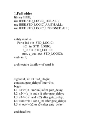
  • 1. 1.Full adder library IEEE; use IEEE.STD_LOGIC_1164.ALL; use IEEE.STD_LOGIC_ARITH.ALL; use IEEE.STD_LOGIC_UNSIGNED.ALL; entity ram1 is Port ( in1 : in STD_LOGIC; in2 : in STD_LOGIC; c_in : in STD_LOGIC; sum, c_out : out STD_LOGIC); end ram1; architecture dataflow of ram1 is signal s1, s2, s3 : std_ulogic; constant gate_delay:Time:=5ns; begin L1: s1<=(in1 xor in2) after gate_delay; L2: s2<=(c_in and s1) after gate_delay; L3: s3<=(in1 and in2) after gate_delay; L4: sum<=(s1 xor c_in) after gate_delay; L5: c_out<=(s2 or s3) after gate_delay; end dataflow;
  • 2. 2. 4:1 MUX (elsif) library IEEE; use IEEE.STD_LOGIC_1164.ALL; use IEEE.STD_LOGIC_ARITH.ALL; use IEEE.STD_LOGIC_UNSIGNED.ALL; entity mux1 is Port ( i : in STD_LOGIC_VECTOR (03 downto 0); s : in STD_LOGIC_VECTOR (01 downto 0); out1 : out STD_LOGIC); end mux1; architecture Behavioral of mux1 is begin process (s) begin if s="00" then out1<=i(0); elsif s="01" then out1<=i(1); elsif s="10" then out1<=i(2); elsif s="11" then out1<=i(3); end if; end process; end Behavioral;
  • 3. 3. 4:1MUX using “when” library IEEE; use IEEE.STD_LOGIC_1164.ALL; use IEEE.STD_LOGIC_ARITH.ALL; use IEEE.STD_LOGIC_UNSIGNED.ALL; entity mux1 is Port ( i : in STD_LOGIC_VECTOR (03 downto 0); s : in STD_LOGIC_VECTOR (01 downto 0); out1 : out STD_LOGIC); end mux1; architecture Behavioral of mux1 is begin out1<= i(0) when (s=”00”) else out1<= i(1) when (s=”01”) else out1<= i(2) when (s=”10”) else out1<= i(3) when (s=”11”) ; end behavioral; 4. 1:4 DeMUX Entity demux_4 is Port (En: in std_logic;
  • 4. Y0,Y1,Y2,Y3: out std_logic; i: in std_logic_vector (01 downto 00)); end demux_4; architecture of demux_4 is begin if i=”00” then Y0<=En; Y1<=’0’; Y2<=’0’; Y3<=’0’; elsif i=”01” then Y0<=’0’; Y1<=’En’; Y2<=’0’; Y3<=’0’; elsif i=”10” then Y0<=’0’; Y1<=’0’; Y2<=’En’; Y3<=’0’; elsif i=”11” then Y0<=’0’; Y1<=’0’; Y2<=’0’; Y3<=’En’; end behavioral;
  • 5. 5. Full Adder (Behavioral) entity Add is port(a,b,ci:in std_logic; s,co: out std_logic); end add; architecture behavioral of Add is begin s<= ‘1’ when (a=’0’ and b=’1’ and ci=’0’) else ‘1’ when (a=’1’ and b=’0’ and ci=’0’) else ‘1’ when (a=’0’ and b=’0’ and ci=’1’) else ‘1’ when (a=’1’ and b=’1’ and ci=’1’) else ‘0’; c0<= ‘1’ when (a=’1’ and b=’1’ and ci=’0’) else ‘1’ when (a=’0’ and b=’1’ and ci=’1’) else ‘1’ when (a=’1’ and b=’0’ and ci=’1’) else ‘1’ when (a=’1’ and b=’1’ and ci=’1’) else ‘0’; end Add;
  • 6. 6. D Latch entity D_latch is port (D: in std_logic; Q: out std_logic); end D_latch; architecture behavioral of D_latch is begin process(clk , D) begin if (clk=’1’) then Q<= D; end if; end process; end behavioral;
  • 7. 7. D F/F (positive and negative edge trigger) entity DFF is port (D: in std_logic; Q: out std_logic); end DFF; architecture behavioral of DFF is begin process(clk , D) begin if (clk ‘event and clk=’1’) then Q<= D; end if; end process; end behavioral;