Dubai Call Girls O528786472 Call Girls Dubai Big Juicy
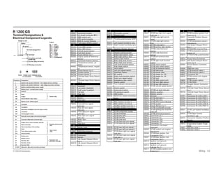
Terminal Designations
1. Wiring - 1/2
R 1200 GS
Te r m in a l D e s ig n a t io n s &
E le c t r ic a l C o m p o n e n t L e g e n d s
R 120 0 G S Intro d u c tio n
A
A9001 In s tru m en t c lu s ter
A9006 O n -b o a rd c o m pu ter (B C )
A9190 AB S c o n tro l u n it
A92 7 0 Z F E c o n tro l m o d u le
A95 00 B M S K C o n tro l M o d u le
A97 00 T heft a la rm (D W A) c o n tro l
B
B 9193 F ro n t AB S s en s o r
B 9194 Rea r AB S s en s o r
B 92 10 V ehic le s peed s en s o r
B 92 2 0 F u el level s en s o r
B 93 2 5 K n o c k S en s o r C y l 1
B 93 2 6 E n g in e s peed & Referen c e
S en s o r
B 95 3 1 C a m s ha ft P o s itio n S en s o r
B 95 5 0 T em pera tu re s en s o r, a ir
in ta k e
B 95 6 2 T em pera tu re s en s o r, en g in e
o il
B 95 8 4 K n o c k S en s o r C y l 2
B 96 90 O x y g en s en s o r 1
B 97 3 8 O x y g en s en s o r 2
B 97 3 9 C y lin d er H ea d T em p S en s o r
C y l 1
B 97 4 0 C y lin d er H ea d T em p S en s o r
C y l 2
E
E 9010 H ea d lig ht
E 9011 L o w b ea m hea d lig ht
E 9012 H ig h b ea m hea d lig ht
E 9013 T a il lig ht
E 9015 S id e lig ht
G
G 92 3 0 B a ttery
G 92 4 0 Altern a to r
H
H 903 0 F ro n t left tu rn s ig n a l
in d ic a to r
H 903 5 Rea r left tu rn s ig n a l
in d ic a to r
H 904 0 F ro n t rig ht tu rn s ig n a l
in d ic a to r
H 904 5 Rea r rig ht tu rn s ig n a l
in d ic a to r
H 905 0 B ra k e lig ht
H 915 0 H o rn
H 93 4 0 Rea r lig ht
K
K 913 0 S ta rter re la y
L
L 95 5 3 E W S Rin g An ten n a
M
M 9100 F u el pu m p
M 913 0 S ta rter
M 95 5 2 Id le S peed S tepper M o to r
C y l 1
M 95 7 9 Id le S peed S tepper M o to r
C y l 2
P
P 9002 Rev o lu tio n c o u n ter
P 92 10 S peed o m eter
R
R95 7 0 T hro ttle po ten tio m eter (D K P )
R993 1 L eft hea ted ha n d leb a r g rip
R993 2 Rig ht hea ted ha n d leb a r g rip
R994 3 G ea rb o x P o s itio n S en s o r
S
S 902 1 H a z a rd w a rn in g s w itc h
S 905 1 B ra k e lig ht s w itc h, ha n d
S 905 2 B ra k e lig ht s w itc h, fo o t
S 906 0 Ig n itio n lig ht s w itc h
S 906 3 B ra k e flu id lev el s en s o r
S 906 4 B ra k e flu id lev el s en s o r
S 907 0 L eft m u lti-fu n c tio n s w itc h
S 907 1 H ig h b ea m s w itc h
S 907 2 H o rn s w itc h
S 907 3 L eft tu rn s ig n a l s w itc h
S 907 4 H ea d lig ht fla s her
S 907 5 B C s w itc h
S 908 0 Rig ht m u lti-fu n c tio n s w itc h
S 908 2 Rig ht tu rn s ig n a l s w itc h
S 908 3 E m erg en c y s to p s w itc h
S 908 4 S ta rter s w itc h
S 908 5 T u rn in d ic a to r c a n c el s w itc h
S 9091 C lu tc h s w itc h
S 9093 S id e-s ta n d s w itc h
S 9095 O il pres s u re s w itc h
S 9195 AB S b u tto n
S 993 0 S w itc h fo r hea ted ha n d leb a r
g rips
T
T 95 06 M a in Ig n itio n C o il C y l 1
T 95 07 M a in Ig n itio n C o il C y l 2
T 95 17 Au x ilia ry Ig n itio n C o il C y l 1
T 95 18 Au x ilia ry Ig n itio n C o il C y l 2
X
X 9001 S T V B in s tru m en t c lu s ter
X 9010 S T V B h ea d lig ht
X 9013 S T V B rea r lig h t -
X 9014 S T V B t a il lig ht
X 9018 S T V B s id e lig ht
X 903 1 S T V B fro n t left tu rn s ig n a l -
X 903 2 S T V B fro n t left tu rn s ig n a l +
X 903 6 S T V B rea r left t u rn s ig n a l -
X 903 7 S T V B rea r left t u rn s ig n a l +
X 904 1 S T V B fro n t rig ht tu rn s ig n a l
in d ic a to r -
X 904 2 S T V B fro n t rig ht tu rn s ig n a l
in d ic a to r +
X 904 6 S T V B rea r rig h t tu rn s ig n a l
in d ic a to r -
X C o n tin u ed
X 904 7 S T V B rea r rig h t tu rn s ig n a l
in d ic a to r +
X 905 1 S T V B b ra k e lig ht s w itc h,
ha n d
X 905 2 S T V B b ra k e lig ht s w itc h,
fo o t
X 905 4 S T V B b ra k e lig ht +
X 906 0 S T V B Ig n itio n lig ht s w itc h
X 906 3 S T V B b ra k e flu id lev el
s en s o r
X 906 4 S T V B b ra k e flu id lev el
s en s o r
X 907 0 S T V B left m u lti-fu n c tio n
s w itc h
X 908 0 S T V B rig ht m u lti-fu n c tio n
s w itc h
X 9091 S T V B c lu tc h s w itc h
X 9093 S T V B pro p s ta n d s w itc h
X 9095 S T V B o il pres s u re s w itc h
X 9100 S T V B fu el pu m p
X 913 0 S T V B s ta rter rela y
X 913 5 S T V B s ta rter ter. 5 0
X 913 6 S T V B s ta rter ter. 3 0
X 915 7 S T V B ho rn
X 9190 S T V B AB S c o n tro l u n it
X 9193 S T V B fro n t AB S s en s o r
X 9194 S T V B rea r AB S s en s o r
X 92 10 S T V B v ehic le s peed s en s o r
X 92 2 0 S T V B fu el lev el in d ic a to r
X 92 3 0 B a ttery po s itiv e
X 92 3 1 B a ttery g ro u n d
X 92 3 8 G ro u n d
X 92 4 1 S T V B a ltern a to r +
X 92 4 2 S T V B a ltern a to r
X 92 7 0 S T V B Z F E C o n tro l M o d u le
X 93 2 1 S T V B s o c k et
X 93 2 5 K n o c k S en s o r C y l 1
X 93 2 6 S T V B C ra n k s ha ft en c o d er
X 93 4 0 S T V B lig htin g /rea r d irec tio n
in d ic a to r
X 93 4 9 S T V B o ptio n a l a c c es s o ry
X 94 01 C o n n ec to r 3 1 I
X 94 12 C o n n ec to r 3 1
X 94 3 0 C o n n ec to r 3 0U
X 94 5 0 C o n n ec to r 15 U
X 94 6 8 C o n n ec to r 15
X 94 7 2 C o n n ec to r L o w b ea m
hea d lig ht
X 95 00 S T V B c o n tro l u n it, en g in e
elec tro n ic s
X 95 06 S T V B M a in Ig n itio n C o il
C o n n ec to r C y l 1
X 95 07 S T V B M a in Ig n itio n C o il
C o n n ec to r C y l 2
X 95 12 Ig n itio n c o il g ro u n d ,
c y lin d er N o . 1
X 95 14 Ig n itio n c o il g ro u n d ,
c y lin d er N o . 2
X 95 17 S T V B Au x ilia ry Ig n itio n C o il
C o n n C y l 1
X C o n tin u ed
X 95 18 S T V B Au x ilia ry Ig n itio n C o il
C o n n C y l 2
X 95 3 1 C a m s ha ft P o s itio n S en s o r
C o n n ec to r
X 95 5 0 S T V B tem pera tu re s en s o r,
in d u c ted a ir
X 95 5 2 Id le S peed S tepper M o to r
C y l 1
X 95 5 3 S T V B E W S An ten n a Rin g
X 95 6 2 S T V B tem pera tu re s en s o r,
en g in e o il
X 95 7 0 S T V B thro ttle po ten tio m eter
X 95 7 2 P u rg e V a lv e C o n n ec to r
X 95 7 9 Id le S peed S tepper M o to r
C o n n C y l 2
X 95 8 4 K n o c k S en s o r C o n n ec to r
C y l 2
X 95 90 D ia g n o s is plu g
X 96 01 S T V B in jec t io n v a lv e 1
X 96 02 S T V B in jec t io n v a lv e 2
X 96 2 7 C o n n ec to r W L
X 96 3 0 S T V B c o n tro l u n it, en g in e
elec tro n ic s II
X 96 90 S T V B o x y g en s en s o r
X 97 00 S T V B D W A I
X 97 3 8 O x y g en S en s o r C o n n ec to r
C y l 2
X 97 3 9 C y lin d er H ea d T em p S en s o r
C y l 1
X 97 4 0 C y lin d er H ea d T em p S en s o r
C y l 2
X 97 6 1 C o n n ec to r M -C AN -L O W I
X 97 6 2 C o n n ec to r M -C AN -H IG H I
X 97 6 3 C o n n ec to r M -C AN -L O W II
X 97 6 4 C o n n ec to r M -C AN -H IG H II
X 97 6 5 C o n n ec to r M -C AN -L O W III
X 97 6 6 C o n n ec to r M -C AN -H IG H III
X 993 1 S T V B L eft hea ted ha n d leb a r
g rip
X 993 2 S T V B Rig ht hea ted
ha n d leb a r g rip
X 994 3 C o n n ec to r G ea rb o x P o s itio n
S en s o r
Y
Y 95 7 2 E v a po ra tiv e S y s tem P u rg e
V a lv e
Y 96 01 In jec tio n v a lv e 1
Y 96 02 In jec tio n v a lv e 2
2. Wiring - 3/4
R 1200 GS
Ligh ting/Tu rn Signals/H orn (Z F E)
(Sch ematic I)
Ignition
S w itc h
L e ft M u ltifu nc tion S w itc h
F ront B ra k e
S w itc h
R e a r B ra k e
S w itc h
R igh t M u ltifu nc tion
S w itc h
Z F E
C ontrol
M od u le
B a tte ry
S id e L igh t H e a d ligh t F ront L e ft B link e r F ront R igh t B link e r H orn T a il L igh t R e a r L e ft B link e r R e a r R igh t B link e r
B M S K
R 1200 GS Introduction
3. Wiring - 5/6
R 1200 GS
P ow er Distrib ution and Grounds
(Schematic II)
BMS K
Control Module
I A BS
Control Module A lternator Starter Starter Relay Ignition Switch
Battery
ZFE Control Module
R 1200 GS Introduction
4. Wiring - 7/8
R 1200 GS
Starter/A lternator (Schematic III) BMS K
Ignition
Switch
ZFE
Control
Module
AlternatorStarterStarter RelayStarter SwitchClutch SwitchSide Stand Switch
G ear
P os ition
Sens or
R 1200 GS Introduction
5. R 1200 GS
B M S K - E n g in e M a n a g e m e n t (Sc h e m a t ic IV )
Wiring - 9/10
Cylinder Head
Tem p S ens o r
(Cyl 1 )
K no c k
S ens o r
(Cyl 1 )
K no c k
S ens o r
(Cyl 2 )
O x yg en
S ens o r
(Cyl 1 )
O x yg en
S ens o r
(Cyl 2 )
M ain Ig nitio n
Co il (Cyl 1 )
M ain
Ig nitio n
Co il (Cyl 2 )
A u x iliary
Ig nitio n
Co il (Cyl 1 )
A u x iliary
Ig nitio n
Co il (Cyl 2 )
F u el Injec to r
( Cyl 1 )
F u el Injec to r
( Cyl 2 )
Idle S p eed S tep p er
M o to r (Cyl 1 )
Idle S p eed S tep p er
M o to r (Cyl 2 )
Th ro ttle
P o tentio m eter
P u rg e
V alv e
P u rg e
V alv e
Intak e A ir
Tem p S ens o r
O il Tem p
S ens o r
O il P res .
S w itc h
Cam s h aft
P o s itio n
S ens o r
E ng ine S p eed
& R eferenc e
S ens o r
G earb o x p o s itio n
S ens o r
S ide S tand S w itc h E W S A ntenna
R ing
Clu tc h S w itc h R ig h t
M u ltifu nc tio n
S w itc h
D iag no s tic
Co nnec to r
S tarter
R elay
F u el P u m p
M o to r
A 9 1 0 0
F u el
P u m p
D riv er
M o du le
Z F E Co ntro l M o du le
B attery
Ig nitio n S w itc h
B M S K Co ntro l M o du le
Cylinder Head
Tem p S ens o r
(Cyl 2 )
R 12 00 G S Intro d u c tio n
6. Wiring - 11/12
R 1200 GS
Integral AB S / I- Cluster(Schematic V ) Integral ABS Control ModulatorIgnition Switch
Battery
ZFE Control Module
I- Cluster
Fuel Lev el
Sensor
Front Brake
Switch
Rear Brake
Switch Alternator Left Multifunction Switch
Rear W heel
Sp eed Sensor
Brake Fluid Lev el Switches
D iagnostic
Connector
Front W heel
Sp eed SensorR 1200 GS Introduction
7. Wiring - 13/14
R 1200 GS
I-Cluster w/out I ABS (Schematic VI)
R 1200 GS
Sock et/Heated Handgrips/
Diagnosis Plug/O ptional
Accessory Sock et
(Schematic VII)
Ignition Switch
Ignition Switch
Right
Multifunction
Switch
ZFE Control Module
Battery
(L) Heated Handgrips (R)O ptional Accessory
Socket
Accessory
Socket
Diagnostic ConnectorBMS K
Control Module
I ABS Control
Modulator
Battery
ZFE Control Module
I-Cluster
Left Multifunction Switch Fuel Level Sensor Speed Sensor
Alternator
R 1200 GS Introduction
8. Wiring - 15/16
R 1200 GS
Anti Theft Alarm System (DW A VI)
(Schematic VIII)
ZFE Control Module
DWA V I (Anti Theft System Control Module)
Battery
I Cluster Ignition Switch BMS K Control Module
R 1200 GS Introduction
9. Wiring - 17/18
R 1200 GS
Electrical Component Locations Diagram I
R 1200 GS Introduction
H ea dligh t a nd C onnector
E 9 010, X 9 010
- L ow B ea m E 9 011
- H igh B ea m E 9 012
E WS Ring A ntenna
L 9 553, X 9 553
F ront B ra k e Sw itch
S9 051, X 9 051
Ignition Sw itch
S9 060, X 9 060
H orn
H 9 150,
X 9 150
P a rk ing L igh t & C onnector
E 9 015, X 9 018
L eft F ront B link er L igh t
H 9 030
- X 9 031 (-)
- X 9 032 (+ )
Righ t F rontB link er L igh t
H 9 040
- X 9 041 (-)
- X 9 042 (+ )
Righ t Rea r
B link er
H 9 045
- X 9 047 (+ )
- X 9 046 (-)
F ront A B S Wh eel Sp eed
Sens or H a rnes s C onn.
X 9 19 3
E ngine O il Tem p Sens or
B 9 562, X 9 562
E ngine Sp eed/Ref Sens or
-X 9 326 (connector)
-B 9 326 (s ens or)
F ront Wh eel Sp eed Sens or
B 9 19 3
O x y gen Sens or 1
B 9 69 0, X 9 69 0
Rea r B ra ke
Sw itch S9 052
C a m s h a ft P os ition
Sens or B 9 531
C a m s h a ft P os ition
Sens or C onnector
X 9 531
C y linder H ea d
Tem p Sens or 1
B 9 739
C y linder H ea d
Tem p Sens or 1
C onn., X 9 739
Idle Sp eed
Step p er M otor 1
M 9 552, X 9 552
F uel Injector 1
Y 9 601, X 9 601
Rea r Wh eel Sp eed
Sens or, B 9 19 4
Rea r B ra ke Sw itch
H a rnes s C onn
X 9 052
Righ t M ultifunction
Sw itch S9 080, X 9 080
Sta rter
Rela y,
K 9 130,
X 9 130
Rea r A B S Wh eel Sp eed
Sens or H a rnes s C onn.
X 9 59 0
D ia gnos tic C onnector
X 9 59 0
Righ t H ea ted Grip
R9 9 32, X 9 9 32
I A B S C ontrol
M odula tor
A 9 19 0, X 9 19 0
Ignition C oils
Ground X 9 512
K nock Sens or 1
B 9 325, X 9 325
M a in Ignition C oil 1
T9 506, X 9 506
A ux ilia ry Ignition C oil 1
T9 517, X 9 517
10. Wiring - 19/20
R 1200 GS
Electrical Component Locations Diagram II
R 1200 GS Introduction
I Cluster
A9001
X9001
Clutch Switch
S9091
X9091
Horn
H9150
X9157
Left Multifunction Switch
S9070
X9070
Left Heated Grip
R9931
X9931
Accessory Connector (Opt)
X9349
Fuel Pump System
X9100
Fuel Lev el Sensor
X9220
B9220
DWA V I Alarm Module
A9700, X9700
Taillight/Blinker
Harness Connector
X9340
Battery G9230
X9231(-), X9230 (+)
Standard Accessory
Socket X9321
Diagnostic
Connector
X9590
Ev aporativ e PurgeV alv e
Y9572, X9572
Side Stand Switch
Connector X9093
Intake AirTemp Sensor
B9550, X9550
I ABS Brake Fluid Lev el Switches and connectors
Front: S9063, X9063 - Rear: S9064, X9064
BMS K Module and Connectors (b eneath Z FE)
A9270, X9270
Z FE Module and Connector
A9500, X9500, X9630
Fuel Pump
Driv er Module
A9100
Fuel Pump
Motor
M9100
Alternator
G9240
X9241
X9242
Ground X9238
Idle Speed Stepper Motor 2
M9579, X9579
Fuel Injector 2
Y9602, X9602
Front Wheel Speed Sensor
B9193
Main Ignition Coil 2
T9507, X9507
Cylinder Head Temp
Sensor 2
T9507, X9507
Ignition Coils Ground
X9514
Throttle Potentiometer
R9570, X9570
Knock Sensor 2
B9584, X9584
Oil Pressure Switch
S9095, X9095 Auxiliary Ignition Coil 2
T9518, X9518
Oxygen Sensor 2
B9738, X9738
Side Stand Switch
S9093
Starter M9130,
X9135, KL50
Starter M9130,
X9136, KL30 Gearb ox
Position
Sensor
R9943,
X9943
Left Rear
Blinker
H9035
- X9036 (-)
- X9037 (+)
Rear Light Assemb ly
E9340
- Taillight fillament E9013
- Connector X9014
- Brake lightfilament H9050
- Connector X9054
- Ground X9013