
Recommandé
Recommandé
Contenu connexe
Tendances
Tendances (20)
En vedette
En vedette (20)
Similaire à EMC Cisco SAP HANA Appliance Disaster Tolerance
Similaire à EMC Cisco SAP HANA Appliance Disaster Tolerance (20)
Plus de EMC
Plus de EMC (20)
Dernier
Dernier (20)
EMC Cisco SAP HANA Appliance Disaster Tolerance
- 1. White Paper EMC Solutions Group Abstract This document describes the basic concepts of a SAP HANA DT (Disaster Tolerance) implementation based on Cisco UCS servers and EMC VNX5300 storage arrays. The SAP HANA DT solution uses storage-based replication enabled using EMC MirrorView/Synchronous (MirrorView/S). September 2013 EMC CISCO SAP HANA APPLIANCE DISASTER TOLERANCE EMC VNX, EMC MirrorView/Synchronous, and Cisco UCS • Scale-out and host auto-failover • Active/passive Disaster Tolerance • Multi landscape solution
- 2. EMC, Cisco, and SAP HANA Appliance Disaster Tolerance 2 Copyright © 2013 EMC Corporation. All Rights Reserved. EMC believes the information in this publication is accurate as of its publication date. The information is subject to change without notice. The information in this publication is provided “as is.” EMC Corporation makes no representations or warranties of any kind with respect to the information in this publication, and specifically disclaims implied warranties of merchantability or fitness for a particular purpose. Use, copying, and distribution of any EMC software described in this publication requires an applicable software license. For the most up-to-date listing of EMC product names, see EMC Corporation Trademarks on EMC.com. All trademarks used herein are the property of their respective owners. Part Number H12342.1
- 3. 3EMC, Cisco, and SAP HANA Appliance Disaster Tolerance Table of contents Executive summary............................................................................................................................... 5 Business case.................................................................................................................................. 5 Solution overview ............................................................................................................................ 6 Introduction ......................................................................................................................................... 7 Purpose ........................................................................................................................................... 7 Scope .............................................................................................................................................. 7 Audience ......................................................................................................................................... 7 Terminology..................................................................................................................................... 8 Technology overview............................................................................................................................ 9 Overview.......................................................................................................................................... 9 EMC VNX Series ............................................................................................................................... 9 VNX customer benefits ................................................................................................................ 9 VNX Software suites available ................................................................................................... 10 Software packs available........................................................................................................... 10 EMC MirrorView.............................................................................................................................. 10 EMC Unisphere .............................................................................................................................. 10 EMC Data Domain .......................................................................................................................... 10 UCS 5108 Chassis.......................................................................................................................... 11 UCS B440 M2................................................................................................................................. 11 Cisco UCS C200 M2 ....................................................................................................................... 11 Cisco UCS 6248UP......................................................................................................................... 11 Cisco Nexus 5596UP...................................................................................................................... 11 Cisco Nexus 2248IP ....................................................................................................................... 12 SAP HANA Database....................................................................................................................... 12 SAP HANA Studio ........................................................................................................................... 12 SAP HANA Client ............................................................................................................................ 12 Solution architecture.......................................................................................................................... 13 SAP HANA scale-out appliance....................................................................................................... 13 Data savepoint.......................................................................................................................... 14 Data and log volumes................................................................................................................ 15 Scale-out ....................................................................................................................................... 15 Appliance components.............................................................................................................. 16 SAP HANA Storage Connector API................................................................................................... 17 EMC block storage and the SAP HANA Storage Connector API.................................................... 17 High Availability – HANA host auto-failover ............................................................................... 18 Disaster Tolerance ......................................................................................................................... 21 Introduction................................................................................................................................... 21
- 4. EMC, Cisco, and SAP HANA Appliance Disaster Tolerance 4 Active/Passive configuration and synchronous replication............................................................. 21 Recovery objectives................................................................................................................... 22 RPO........................................................................................................................................... 22 RTO ........................................................................................................................................... 23 UCS Service Profiles....................................................................................................................... 24 Single landscape solution.............................................................................................................. 24 Scenario 1................................................................................................................................. 24 Multi landscape solution................................................................................................................ 25 Scenario 2................................................................................................................................. 25 HANA backup option...................................................................................................................... 28 Validation........................................................................................................................................... 29 Test objectives............................................................................................................................... 29 Data loading .................................................................................................................................. 29 Data set..................................................................................................................................... 29 SAP HANA data compression..................................................................................................... 29 SAP HANA Studio ...................................................................................................................... 30 SAP HANA HDBSQL.................................................................................................................... 31 Table partitioning...................................................................................................................... 32 Threads and batch..................................................................................................................... 32 Memory usage ............................................................................................................................... 34 Physical memory ....................................................................................................................... 34 Allocated memory ..................................................................................................................... 35 Used memory............................................................................................................................ 35 High Availability............................................................................................................................. 36 Host auto-failover - EMC block storage and the SAP HANA Storage Connector API ..................... 36 SAP HANA Database shutdown ...................................................................................................... 39 Soft shutdown........................................................................................................................... 39 Hard shutdown.......................................................................................................................... 39 SAP HANA Database (re)start..................................................................................................... 39 Disaster Tolerance ......................................................................................................................... 39 Failover ..................................................................................................................................... 40 Failback..................................................................................................................................... 43 Backup .......................................................................................................................................... 44 Conclusion ......................................................................................................................................... 45 Findings......................................................................................................................................... 45 Summary ....................................................................................................................................... 47 References ......................................................................................................................................... 48 EMC Papers.................................................................................................................................... 48 Cisco Papers.................................................................................................................................. 48 SAP Papers .................................................................................................................................... 48
- 5. 5EMC, Cisco, and SAP HANA Appliance Disaster Tolerance Executive summary IT systems have evolved to address an increasingly broad range of capabilities, driven by changing business requirements and enabled by advances in technology. Analytics are being employed to respond to real-time events, in order to improve operational efficiency, to meet or exceed service level agreements, to respond to real- time market conditions, or to predict the next change. In a global business economy that works around the clock, down time for business critical systems is no longer an option. Business continuity in the event of a failure, whether caused by infrastructure failure or unforeseen external events, is essential. Organizations require two critical capabilities to provide constant access to business critical information, meeting service level agreements, and protecting organizational and customer data. First, data center systems must be resilient and capable of self-healing in the event of a component or node failure. This requires that the systems be configured in clusters, with no single points of failure. Redundant components and nodes must be built into the configuration, as well as the ability to maintain a consistent state, with continuous service to users and applications, while individual components or nodes are automatically failed-over. Second, organizations must consider the possibility that a natural disaster or building emergency can cause the temporary or permanent loss of an entire data center. Disaster tolerance between data centers is necessary to provide continuity of service. A standby system, in a separate physical location in the Metro-Cluster, can be configured and managed to take over operations from a failed data center. Both the primary and the standby system must have the ability to maintain consistency. In normal operation, the secondary site can run non-production systems. In the event of an emergency, applications from the primary system will resume on the standby system, while non-production activities are suspended. SAP HANA is a modern platform for real-time analytics and applications. SAP HANA in- memory database is the core technology underlying the SAP HANA platform and is optimized to exploit parallel processing capabilities of modern multi core/CPU architectures. Analytic applications have already seen unprecedented performance gains. Moving forward SAP HANA will increasingly become the common platform for not just analytics applications but core SAP applications, as well. IT professionals will require SAP HANA to be “Data Center Ready”. Protecting SAP HANA environments from system failures or disasters is an important requirement for many SAP customers given the business value of data contained within the HANA environment. The SAP HANA in-memory database, while essential for performance, requires sophisticated storage solutions to maintain persistence of data and business continuity. Business case
- 6. EMC, Cisco, and SAP HANA Appliance Disaster Tolerance 6 SAP HANA is an in-memory data platform that is deployable as an on-premise appliance, or in the cloud. It is a revolutionary platform that is best suited for performing real-time analytics as well as developing and deploying real-time applications. At the core of this real-time data platform is the SAP HANA database, which is fundamentally different than any other database engine in the market today. SAP HANA takes advantage of the low cost of main memory (RAM), data processing abilities of multi-core processors to deliver better performance for analytical and transactional applications. It offers a multi-engine query processing environment that allows it to support: • Relational data • Both row and column-oriented physical representations in a hybrid engine • Graph and text processing • Semi and unstructured data management • ACID compliant The Cisco EMC® SAP HANA appliance delivers a highly available scale-out solution that provides redundancy within the appliance. In the event of a node failure, standby nodes may be configured to take over the workload. This enables IT departments to run big data, growth-oriented applications, and analytics by rapidly scaling to many nodes in high-performance, highly available configurations. This paper provides a complete disaster tolerant solution using EMC storage level replication of the entire HANA appliance to a secondary site. Each of the HANA persistence volumes and file systems are replicated to a remote storage system using synchronous replication. The advantage is a much shorter recovery time objective (RTO) compared to a solution using only backups. This solution also takes advantage of Cisco Unified Computing System (Cisco UCS) innovative, scalable deployment infrastructure. Using UCS Service Profiles, the appliance has the ability to manage individual server identity as a single object. This enables a much greater ROI for the solution since the remote site can operate as a Test/Dev environment under normal circumstances and then seamlessly switch to a Production environment in the event of an outage on the primary site, using the same servers for both functions. The EMC Disaster Tolerance solution using MirrorView/S outlined in this paper is fully validated and certified by SAP and is generally available as of September 2013. Solution overview
- 7. 7EMC, Cisco, and SAP HANA Appliance Disaster Tolerance Introduction This document describes the basic concepts of a SAP HANA DT (Disaster Tolerance) implementation based on Cisco UCS servers and EMC VNX5300 storage arrays. The SAP HANA DT solution uses storage-based replication enabled using EMC MirrorView/Synchronous (MirrorView/S). The scope of the white paper is to: • Give a brief introduction to SAP HANA • Document storage persistence for SAP HANA Single Node • Explore SAP HANA Scale out with High Availability Multi Node • Document the Cisco EMC SAP HANA Appliance • Demonstrate SAP HANA Disaster Tolerance using MirrorView/S to replicate the production environment Multi Site • Document the use of Service Profiles for compute hardware abstraction Multi Landscape • Document the benefits that this solution delivers Reduced RTO Reduced RPO Increased ROI This white paper is intended for system integrators, systems administrators, customers, partners and members of the EMC professional services community. It is assumed that the audience is familiar with the Cisco/EMC SAP HANA appliance, EMC VNX5300 storage systems, and the SAP HANA in-memory database. This white paper is intended for SAP Basis Administrators, storage administrators, IT architects, and technical managers responsible for designing, creating, and managing mission- critical SAP applications in 24/7 landscapes. Purpose Scope Audience
- 8. EMC, Cisco, and SAP HANA Appliance Disaster Tolerance 8 This white paper includes the following terminology. Term Definition ACID Atomicity, Consistency, Isolation, and Durability DR Disaster Recovery DT Disaster Tolerance ROI Return on Investment RPO Recovery Point Objective RTO Recovery Time Objective UCS Unified Computing System UID Unique Identifier SCSI Small Computer System Interface MAC Media Access Control NIC Network Interface Controller DM-MPIO Device Mapper – MultiPath Input Output HDB HANA Database HANA High Performance Analytic Appliance CSV Comma Separated Values Terminology
- 9. 9EMC, Cisco, and SAP HANA Appliance Disaster Tolerance Technology overview The solution uses the following EMC hardware and software components: • EMC VNX5300 • EMC MirrorView™ • EMC Unisphere® The solution uses the following Cisco hardware and software components: • UCS 5108 Chassis • UCS B440 M2 • Cisco UCS C200 M2 • Cisco UCS 6248UP FI • Cisco Nexus 5596UP • Cisco Nexus 2244IP The solution uses the following SAP software components: • SAP HANA Database • SAP HANA Studio • SAP HANA Client The EMC VNX® family is optimized for virtual applications delivering industry-leading innovation and enterprise capabilities for file, block, and object storage in a scalable, easy-to-use solution. This next-generation storage platform combines powerful and flexible hardware with advanced efficiency, management, and protection software to meet the demanding needs of today’s enterprises. The VNX Series is powered by the Intel Xeon processor for intelligent storage that automatically and efficiently scales in performance, while ensuring data integrity and security. VNX customer benefits • Next-generation unified storage, optimized for virtualized applications • Capacity optimization features including compression, deduplication, thin provisioning, and application-centric copies • High availability, designed to deliver five 9s availability • Automated tiering with FAST VP™ (Fully Automated Storage Tiering for Virtual Pools) and FAST Cache that can be optimized for the highest system performance and lowest storage cost simultaneously Overview EMC VNX Series
- 10. EMC, Cisco, and SAP HANA Appliance Disaster Tolerance 10 • Simplified management with EMC Unisphere for a single management interface for all NAS, SAN, and replication needs • Up to three times improvement in performance with the latest Intel Xeon multi- core processor technology, optimized for Flash VNX Software suites available • FAST Suite: Automatically optimizes for the highest system performance and the lowest storage cost, simultaneously. • Local Protection Suite: Practices safe data protection and repurposing. • Remote Protection Suite: Protects data against localized failures, outages, and disasters. • Application Protection Suite: Automates application copies and proves compliance. • Security and Compliance Suite: Keeps data safe from changes, deletions, and malicious activity. Software packs available • Total Efficiency Pack: Includes all five software suites. • Total Protection Pack: Includes local, remote, and application protection suites. EMC MirrorView offers two complimentary storage system based remote mirroring products: • MirrorView/Synchronous • MirrorView/Asynchronous MirrorView/S is a limited-distance synchronous data mirroring facility that provides high-availability and disaster recovery for VNX series arrays. MirrorView/S maintains a synchronized remote mirror of production data between source and destination VNX system pairs at separate locations. EMC Unisphere in the next generation unified storage management platform that provides intuitive user interfaces for EMC storage platforms, including Symmetrix VMAX, VNX, VNXe, VPLEX, and RecoverPoint. Unisphere fosters simplicity, flexibility, self-help, and automation, all key requirements for the journey to the cloud. EMC Data Domain deduplication storage systems dramatically reduce the amount of disk storage needed to retain and protect enterprise data. When data enters a Data Domain system using any of the supported access interfaces—including IP (Common Internet File System (CIFS), network file system (NFS), DD Boost and Fibre Channel (FC) virtual tape library (VTL)—the stream is segmented, fingerprinted, deduplicated, and then locally compressed. DD640 is a midrange appliance in the Data Domain family. Data Domain systems integrate easily into your existing environment so you can take advantage of the benefits of deduplication across workloads, infrastructure, and backup and archiving applications. For example, it enables efficient and non- disruptive backup of large databases such as data warehouses and data marts. EMC MirrorView EMC Unisphere EMC Data Domain
- 11. 11EMC, Cisco, and SAP HANA Appliance Disaster Tolerance In the context of this solution, Data Domain systems integrate seamlessly with SAP HANA without requiring any changes to existing scripts, backup processes, or system architecture. The Cisco UCS 5100 Series Blade Server Chassis is a crucial building block of the Cisco Unified Computing System. It delivers a scalable and flexible architecture for current and future data center needs, while helping reduce total cost of ownership. The Cisco UCS 5108 Blade Server Chassis is six rack units (6RU) high, can mount in an industry-standard 19-inch rack, and uses standard front-to-back cooling. A chassis can accommodate up to eight half-width, or four full-width, Cisco UCS B-Series Blade Servers form factors within the same chassis. The Cisco UCS 5108 Blade Server Chassis revolutionizes the use and deployment of blade-based systems. By incorporating unified fabric and fabric-extender technology, the Cisco Unified Computing System enables the chassis to: • Have fewer physical components • Require no independent management • Be more energy efficient than traditional blade-server chassis The Cisco UCS B440 M2 High-Performance Blade Server extends the Cisco Unified Computing System. It is a four socket server that utilizes the Intel Xeon processor E7- 4800 family. The Cisco UCS B440 M2 is a high-performance blade server that delivers outstanding processing performance, scalability, and mission-critical reliability in a high-density blade form factor. The Cisco UCS C200 M2 server is a high-density, 2-socket, 1 rack unit (RU) rack server built for production-level network infrastructure, web services, and mainstream data center, branch, and remote-office applications. Building on the success of the UCS C-Series servers, the UCS C200 M2 server extends the capabilities of the Cisco Unified Computing System, using Intel's latest Xeon 5600 Series multi-core processors to deliver even better performance and efficiency. The Cisco UCS 6248UP 48-Port Fabric Interconnect is a core part of the Cisco Unified Computing System. Typically deployed in redundant pairs, the Cisco UCS 6248UP Fabric Interconnects provides uniform access to both networks and storage. Cisco Nexus 5000 Series Switches deliver an innovative architecture to simplify data center transformation by enabling a high-performance, standards-based, multi- protocol, multi-purpose, Ethernet-based fabric. They help consolidate separate LAN, SAN, and server cluster network environments into a single Ethernet fabric. Backed by a broad system of industry-leading technology partners, Cisco Nexus 5000 Series Switches are designed to meet the challenges of next-generation data centers, including the need for dense multi- socket, multi-core, virtual machine–optimized services, in which infrastructure sprawl and increasingly demanding workloads are commonplace. UCS 5108 Chassis UCS B440 M2 Cisco UCS C200 M2 Cisco UCS 6248UP Cisco Nexus 5596UP
- 12. EMC, Cisco, and SAP HANA Appliance Disaster Tolerance 12 Cisco Nexus 5000 Series Switches provide: • Architectural flexibility to support diverse business and application needs • Infrastructure simplicity to decrease the total cost of ownership (TCO) • Increased agility and flexibility for traditional deployments with easy migration to virtualized, unified, or high-performance computing (HPC) environments • Enhanced business resilience with greater operational continuity Capability to use existing operational models and administrative domains for easy deployment The Cisco Nexus 2248TP works with upstream Cisco Nexus 5000 Series Switches and Cisco Nexus 7000 Series Switches. The combination offers a cost-effective, scalable server access layer strategy for Gigabit Ethernet and mixed Fast Ethernet and Gigabit Ethernet environments. The SAP in-memory database is a hybrid in-memory database that combines row based, column-based, and object-based database technology and is optimized to exploit parallel processing capabilities of modern multi core/CPU architectures. With this architecture, SAP applications can benefit from current hardware technologies. SAP HANA Studio is both the central development environment and the main administration tool for SAP HANA. Administrators use the SAP HANA Studio, for example, to start and stop services, monitor the system, configure system settings, and manage users and authorizations. The SAP HANA Studio accesses the servers of the SAP HANA database by SQL. Developers can use the SAP HANA studio to create content such as modeled views and stored procedures. These development artifacts are stored in the repository, which is part of the SAP HANA database. The SAP HANA studio is developed in Java and based on the Eclipse platform. SAP HANA Client provides client interfaces for connecting applications to the SAP HANA Database. The SAP HANA Client needs to be installed on all hosts, database servers and client applications hosts that need to connect to the SAP HANA Database. Standard interfaces installed with the SAP HANA Client are: • ODBC − Open Database Connectivity used with SQL (Structured Query Language) • ODBO − OLE DB for OLAP used with MDX ( Multidimensional Expressions) • JDBC − Java Database Connectivity used with SQL • SQLDBC − SAP native database SDK used with BICS (BI Consumer Services) Cisco Nexus 2248IP SAP HANA Database SAP HANA Studio SAP HANA Client
- 13. 13EMC, Cisco, and SAP HANA Appliance Disaster Tolerance Solution architecture The Cisco UCS with EMC Storage for SAP HANA scale-out solution combines the innovative Cisco UCS platform with EMC VNX series unified storage to deliver a high- performance, scalable infrastructure that works right out of the box. Figure 1: Cisco EMC SAP HANA appliance (Single Node) The SAP HANA in-memory database holds the bulk of its data in memory for maximum performance but still uses persistent storage to provide a fallback in case of a failure. The SAP HANA persistence volumes reside on the VNX 5300, each node uses two LUNs, one for data and another for logs as shown in Figure 1. Cisco UCS B440 M2 servers are used as the compute Nodes within the appliance, each server becomes a single HANA node. The VNX array contains the server boot LUNs as well as the SAP HANA shared directories. The rules for persistence are proscribed by SAP and these rules dictate the size of the LUNs required, as shown in Figure 2. SAP HANA scale- out appliance
- 14. EMC, Cisco, and SAP HANA Appliance Disaster Tolerance 14 The Data LUN is sized at three times the physical RAM of the Node. The log LUN must be equal in size to the amount of physical RAM in the Node. Each node also has access to a shared file system. The file system must be equal to the size of physical RAM of the Node multiplied by the total number of Nodes. Figure 2 shows a table with these rules and an example with 4 active nodes. Figure 2: External persistence rules The primary SQL data is kept in memory but asynchronously written to the persistence as a savepoint to the Data LUN every 5 minutes by default. Data also contains undo log information. Information about data changes is directly saved to the persistence Log LUN whenever a transaction is committed or the internal log buffer (1 MB) is full. Figure 3: Persistence mechanism Data savepoint To ensure that the database can always be restored to its most recent committed state, changes to data in the database are periodically copied to disk. Logs containing data changes and certain transaction events are also saved regularly to disk. The data and logs of a system are stored in volumes (LUNs). During the savepoint operation, the SAP HANA database flushes all changed data from memory to the data volumes. The data belonging to a savepoint represents a consistent state of the data on disk and remains so until the next savepoint operation has completed. Redo log entries are written to the log volumes for all changes to persistent data. In the event of a database restart (for example, after a crash), the data from the last completed savepoint can be read from the data volumes, and the redo log entries written to the log volumes since the last savepoint can be replayed.
- 15. 15EMC, Cisco, and SAP HANA Appliance Disaster Tolerance Data and log volumes Each data volume contains one file datavolume_0000.dat ,in which data is organized into pages, ranging in size from 4 KB to 16 MB (page size class). Data is written to and loaded from the data volume page-wise. Over time, pages are created, changed, overwritten, and deleted. The size of the data file is automatically increased as more space is required. However, it is not automatically decreased when less space is required. This means that at any given time the actual payload of a data volume (that is the cumulative size of the pages currently in use) may be less than its total size. The HANA Studio data backup wizard estimates the actual table data (or payload) size of the data volumes of the database. This is a good way to establish the database size in terms of actual data. Each log volume contains the file logsegment_<partition_ID>directory.dat and one or more log segment files logsegment_<partition>_<segment_number>.dat. Log segment files are cyclically overwritten depending on the log mode. The log mode determines how logs are backed up. Log volumes only grow if there are no more segment files available for overwriting. Log segment files that are available for overwriting have been backed up and are not required for a database restart. Scale-out refers to combining multiple independent computers into one system. The main reason for distributing a system across multiple hosts (that is, scaling out) is to overcome the hardware limitations of a single physical server. With planned data growth this means that an SAP HANA system can distribute the load between multiple servers. In a distributed system, each index server is usually assigned to its own host to achieve maximum performance. It is possible to distribute data and to assign different tables to different hosts (partitioning the database), as well as to split a single table between hosts (partitioning of tables). SAP HANA's performance is derived from its efficient, parallelized approach. The more computation cores your SAP HANA server has, the better overall system performance. Scale-out
- 16. EMC, Cisco, and SAP HANA Appliance Disaster Tolerance 16 Figure 4: Cisco EMC Appliance with four active nodes The Cisco EMC Appliance is certified by SAP and can scale to 16 Nodes. This requires a total of sixteen UCS B440 M2 servers and three VNX 5300 arrays. The first VNX 5300 is a Unified array that contains the boot LUNs and shared file systems for all nodes. It also contains persistence LUNs for up to a maximum of six nodes. The remaining two VNX 5300 arrays are block only and they contain the remaining persistence LUNs. Appliance components The major components for a SAP HANA appliance are defined by SAP. The appliance must adhere to this component set to gain certification. The defined components are listed here: • Intel Xeon E7-4870 CPU • 128 GB per CPU socket max • 10 GbE or 8 Gb FC redundant storage connectivity • 10 GbE redundant HANA node to HANA node connectivity • 1 GbE / 10 GbE redundant uplink • Complete the performance test in less than 1500 seconds • I/O performance of the data device has to show >600 MB/sec • SuSE Linux Enterprise Server 11 SP2 or • SuSE Linux Enterprise Server for SAP SP2
- 17. 17EMC, Cisco, and SAP HANA Appliance Disaster Tolerance Based on these requirements Cisco and EMC created the solution documented in this paper. The system architecture is shown in Figure 5. Figure 5: Cisco EMC physical architecture EMC block storage and the SAP HANA Storage Connector API The SAP HANA Storage Connector API for block storage, co-developed with EMC, handles the mounting and reservations of persistence for EMC block storage devices in a scale-out SAP HANA system. SCSI-3 (PGR) persistent group reservations mechanism is used to prevent data corruption to the EMC block storage devices. During startup or failover, the Storage Connector API for block assigns a storage partition (device) to a HANA node, and writes reservation keys to the block devices. The reservation keys allow the owning node only read/write access to the storage partition and prevents access from all other nodes (including read access). This method is called IO fencing. In addition, Native Linux Multipathing (DM-MPIO) is used to provide high availability of access paths and load balancing to the EMC storage devices. The Storage Connector API for block storage is implemented by editing the SAP HANA global.ini file to add the appropriate entries. These entries are based on the array LUN UIDs. SAP HANA Storage Connector API
- 18. EMC, Cisco, and SAP HANA Appliance Disaster Tolerance 18 Figure 6: HDB Studio view of the global.ini file The Storage Connector API is controlled by the nameserver process and is responsible for the following actions: • Mount persistence for all worker nodes during system startup. • Set SCSI-3 PGR reservation on devices to ensure that only the owning node has exclusive access to a single persistence at any point in time. • Clear SCSI-3 reservations when HANA is being shut down normally. • Remount the HANA persistence during HANA Host Auto Failover and ensure the Hana persistence is then fenced off from the failed node. High Availability – HANA host auto-failover This functionality protects against server hardware failures. HANA permanently monitors the status of all processes. If a failure of one server node is detected, HANA automatically shuts down this server and moves the respective data to one of the configured standby nodes. The standby node reads the data of the failing node from the shared storage infrastructure and fully takes over the role of this node. There is no loss of data or of committed transactions.
- 19. 19EMC, Cisco, and SAP HANA Appliance Disaster Tolerance Figure 7: Node failover This HA function works only for scale-out configurations. When the failed node is repaired it assumes the role of a standby node. This functionality does not protect from failures of the underlying storage subsystem. Figure 8 shows a HANA scale-out auto host-failover.
- 20. EMC, Cisco, and SAP HANA Appliance Disaster Tolerance 20 Figure 8: HANA scale-out auto host-failover
- 21. 21EMC, Cisco, and SAP HANA Appliance Disaster Tolerance Disaster Tolerance provides complete protection in the event of a storage system failure or in the event of a failure of the entire production site. This section describes the basic concepts of an SAP HANA DT implementation based on Cisco UCS servers and EMC VNX5300 storage arrays. The SAP HANA DT solution uses the storage based replication, EMC MirrorView/Synchronous (MirrorView/S). MirrorView/S is a limited-distance synchronous data mirroring facility that provides high-availability and disaster recovery for VNX series arrays. MirrorView/S maintains a synchronized remote mirror of production on the destination VNX system at a separate location. In an active/passive configuration, MirrorView/S provides a complete disaster recovery configuration of the SAP HANA database by writing data to two VNX systems in separate locations, using mirrors of source LUNs and their equivalent destination LUNs. This ensures that the second copy of the data associated with the source LUNs, accurate to the last transaction, is available for use at the destination site after a MirrorView/S failover procedure. As shown in Figure 9, in an active/passive MirrorView/S configuration: 1. Data is written to the source VNX system 2. MirrorView/S copies the data to the destination VNX 3. The remote VNX performs a cyclic redundant check (CRC) on the data in cache and sends an acknowledge to the source VNX 4. The write-acknowledge signal is sent to the HANA Node that initiated the I/O request Note: The next write I/O is sent to the destination VNX for block system after the first write is acknowledged in step 3. Figure 9: MirrorView/S active/passive configuration Disaster Tolerance Introduction Active/Passive configuration and synchronous replication
- 22. EMC, Cisco, and SAP HANA Appliance Disaster Tolerance 22 EMC supports synchronous replication of SAP HANA devices over a distance of up to 50 km. MirrorView/S is a replication facility for VNX block, file, and unified systems. The Cisco/EMC SAP HANA appliance uses file and block components in the following way: • File components (only on the primary array within an appliance): − PXE-Boot file systems for all HANA nodes (/FS_OS_01 .. /FS_OS_16) − SAP HANA shared file system (/FS_SAPbin) − File systems for management (/FS_tftpboot, /FS_osmaster) • Block components (on all arrays within an appliance): − HANA persistence per HANA node − Data LUN − Log LUN Since the file components exists on the first (primary) array only, the setup of the MirrorView/S for file components must be done only on the first array. The setup of the replication for the HANA persistence (block components) is required on all arrays within an appliance. Figure 10: Disaster Tolerance architecture diagram Recovery objectives Recovery objectives are service levels that must be met to minimize the loss of information and revenue in the event of a disaster. The criticality of the business application and information defines the recovery objectives. The terms commonly used to define the recovery objectives are recovery point objective (RPO) and recovery time objective (RTO). RPO Recovery point objective (RPO) defines the amount of acceptable data loss in the event of a disaster. The business requirement for RPO is typically expressed as a measure of time. For instance, application A may have zero tolerance for loss of data in the event of a disaster. This is typical for financial applications where a completed transaction must be recovered. Application B may be able to sustain the loss of minutes or hours of data. RPO determines the required update frequency of the
- 23. 23EMC, Cisco, and SAP HANA Appliance Disaster Tolerance remote site. The rate of change of the information determines how much data needs to be transferred. This, combined with the RPO, has a significant impact on the distance, protocol and bandwidth of the link between remote sites. MirrorView provides synchronous replication between the primary and remote sites. The RPO in the event of disaster for the SAP HANA database appliance is close to zero, but depends on the ability of HANA to restart the scale-out appliance from a consistent point-in-time. RTO RTO is defined as the amount of time required to bring the business application back online after a disaster occurs. The RTO of the SAP HANA appliance in a DT environment with storage-based replication depends on the time it takes to restart the HANA nodes at the destination site and to load the HANA database back into memory. This may take several minutes, even hours, depending on the size of the HANA database. However, in most case this is still faster than restoring a backup at the remote site. This Cisco EMC solution is certified by SAP and can scale out to 16 nodes as shown in Figure 11. The appliance can also, in some cases, scale to 32 nodes, but specific approval must be granted by SAP on a case-by-case basis. Figure 11: Scale-out Disaster Tolerance, 16 nodes This shows an active/passive solution, production runs on, Site A (production). As data is written to the array on Site A, it is synchronously replicated to Site B (remote). Site B contains the same storage, network and compute infrastructure as Site A. It is available to start HANA in the event of an outage on Site A.
- 24. EMC, Cisco, and SAP HANA Appliance Disaster Tolerance 24 Every server that is provisioned in the Cisco Unified Computing System is defined using a service profile. A service profile is a software definition of a server and its LAN and SAN network connectivity. In other words, a service profile defines a single server and its storage and networking characteristics. Service profiles are stored in the Cisco UCS 6xxx Series Fabric Interconnects. When a service profile is deployed to a server, UCS Manager automatically configures the server, adapters, fabric extenders, and fabric interconnects to match the configuration specified in the service profile. This automation of device configuration reduces the number of manual steps required to configure servers, network interface cards (NICs), host bus adapters (HBAs), and LAN and SAN switches. The EMC HANA alliance is configured using Unified Computing System Service Profiles. The UCS Sub-Organizations (Sub-Org) T01, T02, T03 and T04 are configured on the appliance. It is recommended to use Sub-Organizations in the following manner: Org Name Main usage T01 Production T02 QA / DT for T01 T03 Test / Dev 1 T04 Test / Dev 2 / DT for T03 Scenario 1 Scenario 1 uses Sub-Org T01 for the Production system. The UCS nodes on Site B use the T01 Sub-Org. When the system is running normally Site A handles all production activity, all data is replicated to the storage on Site B. The network and compute components on Site B are only utilized in the event of an outage at Site A. In the event of an outage on Site A, MirrorView is used to failover to Site B. The nodes are powered on and the production HANA database is then started. Figure 12 shows an example of active/passive sites in a production system only. UCS Service Profiles Single landscape solution
- 25. 25EMC, Cisco, and SAP HANA Appliance Disaster Tolerance Figure 12: Scenario 1 – Active/passive sites production system only Scenario 2 Service Profiles make it easy to repurpose the network and compute portion of the solution. A multi landscape solution uses T02 for QA, T03 for Pre-Prod, Test or Dev systems, and T04 for Test/Dev. With this configuration all WWN and MAC address pools can be predefined and do not end up with duplicate MAC addresses, especially for the customer access network. Select UCS Sub-Organization Cisco has pre-configured four UCS Sub-Organizations to match the SAP multi system landscape requirement. The two main reasons for multiple Sub-Orgs are, unique MAC Addresses on the Access NICs and readiness for HANA DT (Disaster Tolerance) functions. If a customer has more than four solutions, it is required to change the MAC addresses for the Access NIC. See the SAP HANA Technical Reference Guide. Org Name Main usage Mac-Address, Access LAN T01 Production 20:00:25:B5:13:00:xx T02 QA / DT for T01 20:00:25:B5:23:00:xx T03 Test / Dev 1 20:00:25:B5:33:00:xx T04 Test / Dev 2 / DT for T03 20:00:25:B5:43:00:xx Multi landscape solution
- 26. EMC, Cisco, and SAP HANA Appliance Disaster Tolerance 26 Service Profiles Each Sub-Org is configured with sixteen Service profiles (T0x-Server01 – T0x- Server16). Every Service Profile is related to a specific Chassis and Blade slot; this is required to guarantee best performance of the solution. Service Profile Name Chassis Blade Slot T0x-Server01 1 1 T0x-Server02 1 3 T0x-Server03 1 5 T0x-Server04 1 7 T0x-Server05 2 1 T0x-Server06 2 3 T0x-Server07 2 5 T0x-Server08 2 7 T0x-Server09 3 1 T0x-Server10 3 3 T0x-Server11 3 5 T0x-Server12 3 7 T0x-Server13 4 1 T0x-Server14 4 3 T0x-Server15 4 5 T0x-Server16 4 7 Sub-Organizations are used as a means to manage and restrict access to various groups within the IT organization, thereby enabling multi-tenancy of the compute resources. Figure 13 shows a multi solution landscape under normal operations. Site A is running the production SAP HANA database. The UCS servers have the T01 Service Profiles associated. MirrorView replicates the production data to the target VNX on Site B.
- 27. 27EMC, Cisco, and SAP HANA Appliance Disaster Tolerance Figure 13: Multi solution landscape. Normal operation, Service Profile T01 The UCS compute and network resources on Site B have Service Profile T02 associated with them under normal operations. This enables the repurposing of these resources to run QA and Dev. The QA and Dev data is stored on a second VNX 5300 array. In the event of a disaster on Site A, Mirror View is used to failover the storage to Site B. The QA and Dev system on Site B is shutdown and the UCS Service profile is switched from T02 to T01. The production system can then be started up on Site B. The use of Service Profiles ensure that the compute and network hardware changes personality and boots from the correct storage array. All hardware connectivity, such as cabling, is already in place. The Service Profiles utilize the correct zoning to access the VNX that contains the production data. This ensures that the production HANA database can be started quickly in the event of a failover as a result of a planned or unplanned outage on Site A. This is shown in Figure 14. Figure 14: Multi solution landscape. Site A Failure Service Profile now T01
- 28. EMC, Cisco, and SAP HANA Appliance Disaster Tolerance 28 EMC offers several backup and recovery options. For this solution, a Data Domain DD640 was used as a backup target on Site A. Figure 15: Backup on production site It is always recommended practice to have a defined backup strategy. In this case, the backup is required in the unlikely event that HANA is unable to start from a consistent point-in-time after a failure. The backup can also be used to seed the QA and Dev systems. HANA backup option
- 29. 29EMC, Cisco, and SAP HANA Appliance Disaster Tolerance Validation The objective of the tests undertaken for this solution is to demonstrate Disaster Tolerance for the Cisco EMC SAP HANA appliance. For the purposes of this testing, a 1 TB database with three active worker nodes was created. The following tests were used to validate this solution: • Validate SAP auto-host failover (2+1 nodes) • Grow 1 TB database (3+0 nodes) • Failover primary to secondary • Failback secondary to primary • Collate measurements for RPO & RTO Data set The data used to populate the database was taken from many different sources such as: • Open data − Online data repositories • Social media • Data generation scripts The data used was mainly flat files in CSV format. To import the data from CSV files, SAP HANA Studio and SAP HANA HDBSQL were used. Different data sources were selected to ensure that the data loaded was different and varied to ensure that the dataset was not overly compressible. SAP HANA data compression With columnar data stores, very high compression rates can be achieved because the majority of the columns contain only a few distinct values compared to the number of rows. In contrast, columns in Row Stores tend to contain distinct values so compression rates are lower. Column Stores makes it less costly for the SAP HANA database to keep data in main memory and it also speeds up searches and calculations. Dictionary compression, by default, is applied to all columns. Table columns which contain only a comparably small number of distinct values can be effectively compressed by enumerating the distinct values and storing only their numbers. Columns then can be further compressed using different compression methods such as for example run-length encoding, cluster encoding. The SAP HANA database uses compression algorithms to determine which type of compression is most appropriate for a column. Test objectives Data loading
- 30. EMC, Cisco, and SAP HANA Appliance Disaster Tolerance 30 SAP HANA Studio Using the File Import wizard, CSV files can be loaded into the HANA database and the import properties can be defined. Data can be loaded into an existing table or the wizard can create a new table. The wizard also allows you to manage the target table Definitions and Data mappings. Figure 16: Data load using SAP HANA Studio
- 31. 31EMC, Cisco, and SAP HANA Appliance Disaster Tolerance Figure 17: Import properties with the File Import Wizard SAP HANA HDBSQL SAP HANA HDBSQL is a command line tool for executing commands on SAP HANA databases. For larger CSV files, HDBSQL was used to import data into the database. The table definitions were created beforehand with SQL Studio in SAP HANA Studio. Figure 18: Creating partitioned table in SAP HANA Studio With HDBSQL, we connect to the database. Figure 19: Using SAP HANA HDBSQL to connect to the database
- 32. EMC, Cisco, and SAP HANA Appliance Disaster Tolerance 32 The data was imported to the database using the following sample command: IMPORT FROM CSV FILE ‘/backup/survey_data_2TB.csv’ INTO “SCHEMANAME”.”TABLENAME” WITH THREADS 20 BATCH 200000 RECORD DELIMITED BY ‘n’ FIELD DELIMITED BY ‘,’ Figure 20: Sample command to import from CSV file Table partitioning The partitioning feature of the SAP HANA database makes it possible to split column- store tables horizontally into disjunctive sub-tables or partitions. In this way, very large tables can be broken down into smaller, more manageable parts. Partitioning is typically used in distributed systems. A partitioned table can be split in a way that different rows of the table are stored on different index servers (nodes). Some of the advantages of using partitioned table are: • Load balancing in distribution systems • Overcoming the size limitation of column-store tables (2 billion rows) • Partitioning allows operations to be parallelized by using several execution threads. The SAP HANA database supports the following partitioning specifications. Hash partitioning is used to distribute rows to partitions equally for load balancing and to overcome the two billion row limitation. The number of the assigned partition is computed by applying a hash function to the value of a specified column. Round-robin partitioning is used to achieve an equal distribution of rows to partitions. However, unlike hash partitioning, you do not have to specify partitioning columns. With round-robin partitioning, new rows are assigned to partitions on a rotation basis. The table must not have primary keys. Range partitioning can be used to create dedicated partitions for certain values or certain value ranges in a table. Usually, this requires an in-depth knowledge of the values that are used or are valid for the chosen partitioning column. For example, a range partitioning scheme can be chosen to create one partition for each calendar month. Unless table partitioning is used, tables will get created and stored on a single host. By default, new tables are distributed across available index servers using a round- robin approach. In order to balance the large tables across multiple indexservers (nodes), table partitioning was used for these tests. Threads and batch Threads and batch can be used to achieve high loading performance by enabling parallel loading and also by committing many records at once. When using threads and batch a general recommendation from SAP for column tables is the use of 10 parallel loading threads, with a commit frequency of 10,000 records or greater.
- 33. 33EMC, Cisco, and SAP HANA Appliance Disaster Tolerance Each USC server has 40 cores (4 sockets * 10 cores). With three active nodes in our testing landscape, this means 120 threads are available in our database. Batch size can depend on the table width (number of columns). Using threads may impact the speed of the database as more threads use more resources. To illustrate the SAP HANA loading performance using Threads, Batch and partitioned tables, some tests were executed using iterating loads with different parameters. For a CSV with 50M records (3.2 GB file size) it can take 1548 seconds (25 minutes) to load into HANA using default parameters to a single non-partitioned table. With threads and batch, the table load time can be reduced to just 36 seconds for a non- partitioned table and 16 seconds for a distributed partitioned table. Figure 21: Iteration of loads with SAP HANA HDBSQL
- 34. EMC, Cisco, and SAP HANA Appliance Disaster Tolerance 34 Threads Batch Non Partitioned Table (seconds) Distributed Partitioned Table (seconds) Default Default 1548 919 Default 10000 445 298 10 10000 57 42 10 200000 40 27 20 10000 52 26 20 200000 36 16 20 400000 39 20 40 10000 47 22 40 200000 37 20 80 10000 45 20 80 200000 37 18 120 10000 46 23 120 200000 37 17 Figure 22: 20 Treads with a Batch size of 200000 was best for this environment Using the test database, a simple table was used with 9 columns. Performance improved with faster loading with the batch size increased to 200000. There was no performance improvement at batch sizes greater than 200000. If wider tables were used Batch sizes less than 200000 may perform better. A significant performance improvement is noticeable when using threads. However, there was no real performance improvement when using more than 20 threads. The optimal load performance for this environment occurred when using a partitioned table with 20 threads and a batch size of 200000. All subsequent datasets were loaded using these parameters until the database size was grown to 1 TB. Physical memory Physical memory is the total amount of physical memory available in the node. The test landscape has a total of 1536 GB (3 active nodes * 512 GB) of physical memory available. Memory usage
- 35. 35EMC, Cisco, and SAP HANA Appliance Disaster Tolerance Allocated memory Allocated memory is the memory pool reserved by SAP HANA from the system. The SAP HANA database (across its different processes) reserves a pool of memory before actual use. This pool of allocated memory is pre-allocated from the operating system over time, up to a predefined global allocation limit, and is then efficiently used as needed by the SAP HANA database code. More memory is allocated to the pool as used memory grows. If used memory nears the global allocation limit, the SAP HANA database may run out of memory if it cannot free memory. The default allocation limit is 90% of available physical memory, but this value is configurable; for example, when the licensed memory is lower than the physical memory available. Used memory Used memory refers to total amount of physical memory used by the SAP HANA database including the program code and stack, all data and system tables, and the memory required for temporary computations. Using the default global allocation limit in the test landscape means the allocation memory limit of 90% is set at 1382.4 (460.8 GB on each node). It is important to note that SAP HANA requires allocated memory to run its processes and perform computations; therefore, this needs to be considered when loading data to avoid out of memory issues. Figure 23: SAP HANA memory usage
- 36. EMC, Cisco, and SAP HANA Appliance Disaster Tolerance 36 Host auto-failover - EMC block storage and the SAP HANA Storage Connector API The SAP HANA database on a scale-out solution has built-in software high availability based on a master slave implementation. One (or more) standby hosts are added to a SAP HANA system and configured to work in standby mode. As long as they are in standby mode, the databases on these hosts do not contain any persistence and do not accept requests or queries. In the event of an active host failure and a standby node is available, the HANA nameserver recognizes the failed server, a new reservation is written on the standby node, the persistence is remounted, and the In-memory database is reloaded on this node. This standby node now becomes an active worker node. The failed node then become a standby node when available again. Figure 24 shows the test SAP HANA Database running on three nodes (server 02a, server03a and server04a). Figure 24: HDB Admin showing SAP HANA Database on 3 nodes The landscape view shows there is no persistence mounted (storage partition) on server04a and the role of the indexserver is standby, as shown in Figure 25. Figure 25: Node 3 (server04a) is a standby node, 2 + 1 configuration Figure 26 shows that the system is distributes across three nodes (hosts). Figure 26: SAP HANA Studio – Distributed system High Availability
- 37. 37EMC, Cisco, and SAP HANA Appliance Disaster Tolerance Figure 27 shows the SAP HANA Studio view of the landscape; again note that indexserver of server04a is in configured as standby. Figure 27: SAP HANA Studio – Landscape Configuration This can also be seen at the OS level. Persistence LUNs are mounted to the worker nodes. The standby node does not have persistence mounted as shown in Figure 28. Figure 28: Persistence mounted on active worker nodes – standby node has no persistence mounted In a failover situation, the HANA nameserver process recognizes there is an issue with server03a, as shown Figure 29. Figure 29: One of the active nodes has lost power Server03a is now powered down and failover about to start, as shown in Figure 30. Figure 30: One of the active nodes is shutdown
- 38. EMC, Cisco, and SAP HANA Appliance Disaster Tolerance 38 The failover has started. The persistence LUNs that were previously mounted to server03a are now mounted to server04a and the indexServer role is switched to slave, as shown in Figure 31. Figure 31: Storage Partition 2 (persistence) has switched from server03a to server04a Figure 32 shows the IndexServer process is running on server04a. Figure 32: Server04a is now an active worker node (slave) Figure 33 shows that a check on OS level confirms that the persistence previously mounted on server03a is now mounted on server04a. Figure 33: SAP Storage Connector API for Block has mounted the persistence on server04a Failover is now complete and server04a has completely taken over from the failed server03a, as shown in Figure 34. Figure 34: Server03a is now on standby still not available
- 39. 39EMC, Cisco, and SAP HANA Appliance Disaster Tolerance When server03a is restored and the HANA database started on that node, server03a becomes the active standby node, shown in Figure 35. Figure 35: Server03a is now the active standby node and will take over should another node fail Soft shutdown The system is stopped gracefully after all running transactions have completed or the specified timeout is reached. A soft shutdown triggers a savepoint operation before all services are stopped. During the savepoint operation, all modified data is written to disk. Hard shutdown The system is stopped immediately. Open transactions are aborted and rolled back. A hard shutdown does not force a savepoint operation. Therefore, a subsequent restart may take longer. During a SAP HANA startup: All row-store tables are loaded into the main memory during instance startup. These include all the SAP HANA DICTIONARY tables that must be available in memory. The size of the Row-store tables significantly influences the startup time of the database. Column-store tables will be loaded on demand when queried (lazy loading). This ensures a quicker startup of the database. After startup the database performance may be slightly slower for a short time. It is also possible to specify critical data, columns, or entire column based tables for pre-load into main memory. The redo log is processed if a hard shutdown occurred – that is all the changes of committed transactions that were not written since the last savepoint are replayed to return the database to its last consistent state. The 1 TB database used for this test contains 61 GB of row-store tables loaded into memory during startup. The average database startup time is between 6 and 7 minutes. MirrorView provides a synchronous replication between Sites A (source) and Site B (remote). The RPO in an event of disaster for the SAP HANA database appliance is close to zero. SAP HANA Database shutdown SAP HANA Database (re)start Disaster Tolerance
- 40. EMC, Cisco, and SAP HANA Appliance Disaster Tolerance 40 Figure 36: HANA running on the primary site Figure 36 shows the HANA landscape running on Site A, the primary site. Note the SID and the serial numbers of the array and UCS chassis. Failover In the event of a disaster or unavailability of Site A, the SAP HANA database needs to failover to Site B. This is a manual process and includes the following steps. • Activate the file components on the target array at Site B • Promote the HANA node persistence LUNs on Site B • Update the SAP HANA Storage Connector API entries in the global.ini file • Associate the corresponding UCS T01service profiles to the UCS blades at the destination site (if required) • Boot the UCS blades at Site B • Start the SAP HANA database at Site B
- 41. 41EMC, Cisco, and SAP HANA Appliance Disaster Tolerance Figure 37: Unisphere view File and Block Consistency Groups available after failover When the failover is complete, the SAP HANA Storage Connector API global.ini file must be updated to point to the persistent LUNs at the destination site. This is completed using a script provided. Figure 38: Output of Script to update global.ini file If the destination site is used for QA and Dev, then the UCS service profiles must also be changed after the failover. Scripts are also provided to disassociate the QA and Dev Service Profile T02 and associate the production Service Profile T01.
- 42. EMC, Cisco, and SAP HANA Appliance Disaster Tolerance 42 Figure 39: Changing the UCS Service Profile The servers are then booted with the T01 Service Profile attached. The Service Profile gives the personality of the production environment. The SAP HANA Database is then restarted on the remote site (Site B). Figure 40 shows the landscape up and running on Site B. The SID is the same as site A as the production HANA database has been failed over. The underlying hardware now reflects the serial numbers on the appliance on Site B. Figure 40: HANA running on remote site; same SID, different serial numbers on both the EMC array and the UCS chassis
- 43. 43EMC, Cisco, and SAP HANA Appliance Disaster Tolerance Failback Restoring the SAP HANA database to the source site once a disaster event has been solved is a three-phase process which requires careful planning and preparation since it requires database downtime. The three phases including the following: 1. Recover the source site 2. Re-establish the mirror pairs and re-synchronize from Site B to Site A a. HANA Database continues to run on Site B 3. Restart the SAP HANA database at the source site a. Shutdown HANA on Site B b. Activate the file components on the primary array at Site A c. Promote the HANA node persistence LUNs on Site A d. Update the SAP HANA Storage Connector API entries in the global.ini file e. Boot the UCS blades at Site A f. Start the HANA Database at Site A The SAP HANA Storage Connector API entries in the global.ini are updated using the script provided. Figure 41 shows the output of the script. Figure 41: Updating the SAP HANA Storage Connector API global.ini In a multi solution landscape, once production is fully restored on Site A the non- production systems can then be restarted on Site B. The T02 UCS service profiles are first associated with the UCS blades at the Site B.
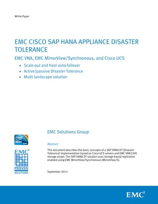
- 44. EMC, Cisco, and SAP HANA Appliance Disaster Tolerance 44 After each data load, the database was backed up to the DD640. The backup was used as a Golden Copy for the duration of the tests. Figure 42 shows the length of time it took the backup to complete, in minutes. Figure 42: Back up duration and dataset size After the initial backup, the database was deleted and the load process was repeated. Figure 43 shows the global and local compression rates achieved on the Data Domain DD640 as well the overall deduplication rate. Figure 43: Compression and deduplication 0 10 20 30 40 50 1 2 3 4 5 6 7 M i n u t e s Load Backup Duration 0 200 400 600 800 1000 1200 1 2 3 4 5 6 7 GB Load Data Backed Up Backup
- 45. 45EMC, Cisco, and SAP HANA Appliance Disaster Tolerance Conclusion The times were measured with the following conditions: • Three worker nodes − 2 sites; 3 on each; 6 in total • Planned and unplanned outages • ≈ 1 TB of data − Data on disk • Distance 0 KM & 25 KM − The sync time was the only parameter affected by the latency introduced by distance Site Function Duration (Minutes) Primary Boot Nodes 7 Primary Start HANA 7 Failover (T01 only) Primary Stop HANA & shutdown Nodes 41 Primary & Secondary Failover Storage 28 Secondary Mount File Systems & Boot Nodes 13 Secondary Start HANA 7 RTO (total time to restart HANA on secondary site) 48 RPO Near 0 Failover (T01 & T02) Primary Stop HANA & Shutdown Nodes 41 Primary & Secondary Failover Storage 28 Secondary Shutdown QA/Dev 102 Secondary Disassociate T02 Service Profile 92 Secondary Associate T01 Service Profile 92 Secondary Mount File Systems & Boot Nodes 13 Secondary Start HANA 7 RTO (total time to restart HANA on secondary site) 48 RPO Near 0 1 Not relevant to RTO. 2 Function performed in parallel. Findings
- 46. EMC, Cisco, and SAP HANA Appliance Disaster Tolerance 46 Site Function Duration (Minutes) Failback (T01 only) Primary Secondary Re-sync Storage --3 Secondary Stop HANA & Shutdown Nodes 4 Primary Secondary Failback Storage 43 Primary Mount File Systems & Boot Nodes 10 Primary Start HANA 7 RTO (Total time to restart HANA on primary site) 64 RPO Near 0 Failback (T01 & T02) Primary Secondary Re-sync Storage --3 Secondary Stop HANA & Shutdown Nodes 4 Primary Secondary Failback Storage 43 Primary Mount File Systems & Boot Nodes 10 Primary Start HANA 7 Secondary Disassociate T01 Service Profile 94 Secondary Associate T02 Service Profile 94 Secondary Start HANA 64 RTO (Total time to restart HANA on primary site) 64 RPO Near 0 3 Data re-sync is a background process and is seamless to the operation. 4 Brining QA/Dev back online at the secondary site is a separate process. Note: All time measurements were obtained in a controlled lab environment with the test HANA landscape configuration, as described. Results obtained in other operating environments with different HANA landscape configurations may vary.
- 47. 47EMC, Cisco, and SAP HANA Appliance Disaster Tolerance Disaster Tolerance for the Cisco EMC SAP HANA Appliance enables a remote system to assume the workload of a production HANA Database in the event of a catastrophic failure, without losing committed changes to the database. Within the solution, local and remote consistency pairs ensure all storage devices are synchronized as changes are made to the production system. Because data is replicated synchronously, less time is needed to get the remote system operational. The replication is enabled by EMC MirrorView/S. The EMC DT solution using MirrorView is fully validated and certified by SAP and is generally available as of September 2013. The synchronous DT solution utilizes UCS Service Profiles as a unique feature to increase the ROI of this solution. Service Profiles enable the use of the compute and network resources on the remote site for QA & Dev under normal operating conditions. In the event of a planned or unplanned outage on the primary site the Service Profile can be quickly changed to that of the production system. Summary
- 48. EMC, Cisco, and SAP HANA Appliance Disaster Tolerance 48 References For additional information, see the white papers listed below. • EMC VNX Series – Using MirrorView Synchronous with VNX for File for Disaster Recovery (P/N 300-013-442) • MirrorView Knowledge Book Releases 30 – 32. A detailed Review • EMC Data Domain Deduplication Storage Systems: SAO HANA Date Protection White Paper For additional information, see the product documents listed below. • UCS 6248 Hardware Installation Guide • UCS 5108 Hardware Installation Guide • UCS B440 M2 Installation Notes • Nexus 5000 Hardware Installation Guide • Nexus 2000 Hardware Installation Guide • Cisco 2911 Integrated Services Router • UCS C220 M3 Hardware Installation Guide • UCS R Series Rack PDU installation Guide For additional information, see the documents listed below. • SAP HANA Administration Guide • SAP HANA SQL and System Views Reference • SAP Note 1755396 - Released DT solutions for SAP HANA with disk replication EMC Papers Cisco Papers SAP Papers