SlideShare une entreprise Scribd logo
1  sur  21
Télécharger pour lire hors ligne
(12) INTERNATIONAL APPLICATION PUBLISHED UNDER THE PATENT COOPERATION TREATY (PCT)
WO 2006/045333                                                      PCT/EP2004/012159
                                             1


                                   PERMANENT MAGNET MACHINE


Field of the invention


This invention relates to a magnetic repellent motor, or drive mechanism. Such a
mechanism may be useful for driving an electrical generation means, a vehicle, a
vessel, an aircraft or the like.


Background to the invention

Conventional power sources rely on fossil fuels or secondary power sources such
as nuclear power or electricity derived by whatever means for its source of driving
power.


All of the above sources of power suffer from disadvantages such as being the
cause of pollution, requiring transportation or transmission over long distances to
the point of use, and being costly to purchase.


Thus, there is a need for a power source which is substantially pollution-free to
operate, requiring substantially no external power, and is simple to maintain.


Summary of the invention


The invention provides a magnetic repellent motor which comprises: a shaft
rotatable about its longitudinal axis, a first set of magnetic sources arranged about
the shaft in a rotor for rotation with the shaft, and a second set of magnetic sources
arranged in a stator surrounding the rotor, wherein the second set of magnetic
sources is in magnetic communication with the first set of magnetic sources,
wherein the magnetic sources of the first and second sets of magnetic sources are
at least partially magnetically screened so as to direct their magnetic field into a
gap between the two sets of magnetic sources. Thus, the interaction of at least
some of the magnetic sources of the first and second set urges the shaft to rotate.
WO 2006/045333                                                      PCT/EP2004/012159
                                             2


The interaction may be the net repelling force of like magnetic poles repelling each
other thereby urging the magnetic sources away from each other, however, since
only the magnetic sources of the first set of magnetic sources are able to be
displaced under the urging of the force, the shaft is urged to rotate into a position in
which the repelling force is less.


The rotor may be substantially disc shaped, and the first set of magnetic sources
may be located in a peripheral region of the rotor which rotates together with the
shaft.


The stator may be in the form of a pair of arms, which co-operates with the
corresponding rotor.


The arms of a pair may be displaceable relative to each other a n d their
corresponding rotor, such that a gap between the arms and the rotor may be
selectively set. The gap may be set manually, for example by a hand wheel, or
automatically, for example by a centrifugal distributed weights system, thereby to
effect control over the rotational speed of the shaft, i.e. the smaller the gap the
greater the repulsion forces between the magnetic sources of the rotor and the
stator.


The rotor may have a plurality of magnetic source receiving zones provided therein
for receiving the magnetic sources of the first set of magnetic sources.


The stator may have a plurality of magnetic source receiving zones provided
therein for receiving the magnetic sources of the second set of magnetic sources.


The receiving zones may be in the form of circumferentially extending spaced apart
sockets.


The sockets may be substantially cylindrical and may be arranged in a plane
perpendicular to the longitudinal axis of the shaft.
WO 2006/045333                                                        PCT/EP2004/012159
                                             3


The sockets may be angled at an acute angle relative to the tangent to the
circumference of the rotor at the mouth opening of its sockets and to the inner
circumference of the stator at the mouth opening of its sockets.


This angle may be between 18 degrees and 40 degrees, preferably between 30
degrees to 35 degrees.


The sockets may receive or incorporate a socket lining consisting at least partially
of a magnetic screening material. The socket lining may line the entire extent of the
sockets so that only the opening to the exterior remains unlined.


The socket lining may comprise a shield of another magnetic screening material.
The shield may envelop the entire extent of the socket lining so that only the
opening to the exterior remains unlined. In another preferred embodiment, the
shield covers a substantial percentage of the socket lining, e.g. 50% thereof.


The magnetic sources may be Nd-fe-B magnets sized and dimensioned to snugly
fit into the sockets and socket linings, respectively.


The magnetic sources may be constituted by a 37mm diameter 75mm length
cylindrical magnet having 360000 gauss.


The socket lining, the shield and the magnetic sources may comprise through holes
to receive a securing pin, preferably in a direction parallel to the longitudinal axis of
the shaft.


The number of sockets in the rotor and the corresponding stator may differ so that
there is not a one to one relationship between the sockets in the rotor and the
sockets in the corresponding stator. Likewise, the number of magnetic sources in
the first and second sets may differ so that a proportion of the magnetic sources of
the two sets are out of register at any given time. Some sockets may be empty i.e.
without a magnetic source, in either the rotor or the stator, or in both.
WO 2006/045333                                                   PCT/EP2004/012159
                                              4


The magnetic repellent motor may have one or more rotors and stators of the
above type arranged in a stack.


It is preferable for magnetic sources of adjacent rotors to be out of register i.e.
staggered or offset relative to each other.


Description of the drawings

Without in any way limiting the scope of the invention, the invention will now be
illustrated with reference to the accompanying drawings.


Fig. 1        is a perspective view showing a rotor of the magnetic repellent motor
              according to the invention;


Fig. 2        is a perspective view showing a stack of rotors of Fig. 1 in assembled
              arrangement;


Fig. 3        is a perspective view showing a left arm of a stator of the magnetic
              repellent motor according to the invention;


Fig. 4        is a perspective view showing a right arm of a stator of the magnetic
              repellent motor according to the invention;


Fig. 5       is a perspective view showing a stack of stators of Fig. 3 and 4 in
             assembled arrangement;


Fig 6        is a perspective view showing a socket lining of a stator or a rotor of
             the magnetic repellent motor according to the invention;


Fig. 7       is a perspective view showing a magnetic source of the magnetic
             repellent motor according to the invention; and
WO 2006/045333                                                     PCT/EP2004/012159
                                           5


Fig. 8        is a perspective view showing one embodiment of the magnetic
              repellent motor according to the invention coupled to an electrical
              generator.


Description of preferred embodiments


Referring to Fig. 1, a substantially disk-shaped rotor 10 is made of a non-magnetic
material. The rotor 10 comprises a plurality of magnetic source receiving zones 12
provided therein for receiving magnetic sources 28 (shown in later figures) of a first
set 16 of magnetic sources. The receiving zones 12 are in the form of
circumferentially extending spaced apart and substantially cylindrical sockets 18
which are located in a plane perpendicular to the rotational axis of the rotor 10 in a
peripheral region thereof.


In the region of the sockets 18, the rotor 10 further comprises through holes 20
arranged in its side surfaces 22 and extending parallel to the rotational axis of the
rotor 10. The rotor 10 further comprises a centre hole 24 for receiving a shaft 26
(shown in later figures).


The sockets 18 are preferably angled at an acute angle relative to a tangent to the
circumference of the rotor 10 at the mouth opening of the sockets 18. Preferably,
this angle is between 18 and 40 degrees, more preferably between 30 a n d 35
degrees. In. one particularly preferred embodiment the angle is 34 degrees.


A shown in Fig. 2, the sockets 18 receive (or incorporate) a socket lining 28 (shown
in more detail in later figures) which is at least partially made of a magnetic
screening non-metallic or metallic material, for example graphite. The socket lining
28 covers the entire extent of the sockets 18 so that only the opening to the exterior
remains uncovered.


In the rotor assembly 30 shown in Fig. 2, three rotors 10 have been stacked in a
row on the shaft 26. The connection between the rotors 10 and the shaft 26 as well
as the connection between the multiple rotors 10 can be established via linking
means known in the art. In general, the magnetic repellent motor 1 may h a v e any
WO 2006/045333                                                        PCT/EP2004/012159
                                             6


number of rotors 10 and corresponding stators 32, since the effect of operating
several rotors 10 in parallel is accumulative. However, it may be useful for a
smooth operation of the motor 1 to arrange the rotors 10 such that the magnetic
sources of adjacent rotors 10 are staggered or offset relative to each other.


Referring to Fig. 3 and 4, a stator 32 is depicted. The stator 32 is made of a non-
magnetic material. The left arm 34 shown in Fig. 3 and the right arm 36 shown in
Fig. 4 combine to form the stator 32. Each of the arms 34, 36 has a substantially
semicircular shape and is adapted to enclose the corresponding rotor 10 in radial
direction while still leaving a gap between the stator 32 and the rotor 10. The arms
34, 36 of one stator 32 are dispiaceabie relative to each other and their
corresponding rotor 10 such that the gap between the arms 34, 36 and the rotor 10
may be selectively set.


The stator 32 comprises a plurality of magnetic source receiving zones 38 provided
therein for receiving magnetic sources 40 (shown in later figures) of a second set
42 of magnetic sources. The receiving zones 38 again are in the form of
circumferentially extending spaced apart and substantially cylindrical sockets 44
which are located in a plane perpendicular to the longitudinal axis of the shaft 26.


In the region of the sockets 44, the stator 32 comprises through holes 46 arranged
in its side surfaces 48 and extending parallel to the longitudinal axis of the shaft 26.


The sockets 44 are again preferably angled at an acute angle relative to a tangent
to the inner circumference of the stator 32 at the mouth opening of the sockets 44.
Preferably, this angle is between 18 and 40 degrees, more preferably between 30
and 35 degrees. The angle of the sockets 18 and 44 and the relative positioning
between them has to be adjusted to allow for a good performance of the motor 1.


Fig 5 shows a stator assembly consisting of three stators so as to fit to the rotor
assembly of Fig. 2. As described with reference to the sockets 18 of Fig. 2, the
sockets 44 receive (or incorporate) a socket lining 50 (shown in more detail in later
figures) which is at least partially made of a magnetic screening non-metallic or
WO 2006/045333                                                       PCT/EP2004/012159
                                             7


metallic material. The socket lining 50 covers the entire extent of the sockets 44 so
that only the opening to the exterior remains uncovered.


Referring to Fig. 6, a socket lining 28, 50 of the rotor 10 or the stator 32 is depicted
in more detail. The socket lining 28, 50 is formed to fit into the sockets 18, 44 and
may fully be made of a non metallic or a metallic material which has magnetic
screening properties. In one preferred embodiment the socket lining 28, 50 is made
of diamagnetic graphite and is partially surrounded by an additional shield 52 of a
material having strong magnetic screening properties, e.g. stainless steel. In the
embodiment shown in Fig. 6, the shield 52 surrounds about 5 0 % of the socket
lining surface.


Thus, by at least partially covering the sockets 18, 44 with a magnetic screening
material the magnetic field of inserted magnetic sources 14, 40 is, so to say,
focused axially with the socket 18, 44, rather than dissipated about the magnets.


Further, through holes 54 are provided in the socket linings 28, 50 which
correspond to through holes 20 and 46 in the rotor 10 and stator 32, respectively.
Thus, a retaining pin 56 may be inserted after the magnetic source 14, 40 has been
put in the socket 18, 44 to detachably fix the magnetic source 14, 40 to the socket
lining 28, 50 and the socket 18, 44 so as to prevent expulsion of the magnetic
sources 14, 40 during operation.


Fig. 7 shows a typical magnetic source 14, 40 used in the motor 1 according to the
invention. The magnetic sources 14, 40 may be natural magnets, induced magnets
or electromagnets. The magnetic source for example is a Nd-fe-B magnet sized
and dimensioned to snugly fit into the socket 18, 44 and socket lining 28, 50,
respectively. In one preferred embodiment, the magnetic source 18, 44 is a
substantially cylindrical shaped magnet and preferably has a diameter of 37mm, a
length of 75mm and provides 360000 gauss. However, the magnetic source 18, 44
may   be   shaped    differently   than   cylindrical   and   may   comprise   different
characteristics. In any case, the magnetic source 18, 44 has to comprise an
through hole 58 for receiving the retaining pin 56.
WO 2006/045333                                                     PCT/EP2004/012159

                                           8


The magnetic repellent motor 1 of the example of Fig. 8 is mounted on a frame 60
and is coupled to an electrical generator 62. In this specific embodiment, the motor
1 comprises three rotors 10 of the above type which are mounted on a single
rotating shaft 26 and work with three stators 32 of the above type to urge the shaft
26 to rotate about its longitudinal axis. The shaft 26 of the mechanism may be
connected to a gearbox to obtain mechanical advantage. The stator arms can be
moved e.g. by a stepper motor 62.


The number of sockets in the rotors 10 and their corresponding stators 32 may
differ such that there is not a one to one relationship between t h e sockets 18 in the
rotor 10 and the sockets 44 in the corresponding stator 32. Likewise, the number of
magnetic sources in the stator 32 and the rotor 10 may differ so that a proportion of
the magnetic sources 14, 40 are out of register at any given time. Some sockets
may be empty i.e. without a magnetic source, in either the rotor 10 or the stator 32,
or both.


The sockets 18 of the rotors 10 can be staggered i.e. offset relative to the sockets
of adjacent rotors or they can line-up in register. Thus the magnetic repellent motor
1 may be time-tuned by the relative positioning of the magnetic sources 14 of
adjacent rotors 10.


Thus, the interaction of at least some of the magnetic sources 1 4, 40 of the first and
second set 16, 42 urges the shaft 26 to rotate. Once the shaft 26 begins to rotate
the plurality of simultaneous interactions causes the shaft 26 to continue rotating.


As mentioned before, the magnetic repellent motor 1 may have any number of rotor
10 and stator 32 sets. Although the precise adjustment of t h e motor elements is
important, one may imagine other embodiments covered by the invention according
to the appended claims.
WO 2006/045333                                                   PCT/EP2004/012159

                                               9


                                          Claims


1.      A magnetic repellent motor which comprises:


         a shaft (26) rotatable about its longitudinal axis,


        a first set (16) of magnetic sources (14) arranged about the shaft (26) in at
        least one rotor (10) for rotation with the shaft (26),


        and a second set (42) of magnetic sources (40) arranged in at least one
        stator (32) surrounding the rotor (10), wherein the second set (42) of
        magnetic sources (40) is in magnetic communication with the first set (16) of
        magnetic sources (14),


        wherein the magnetic sources (14, 40) of the first and second sets (16, 42)
        of magnetic sources are at least partially magnetically screened so as to
        direct their magnetic field into a gap between the two sets (16, 42) of
        magnetic sources.


2.      The magnetic repellent motor according to claim 1, wherein the rotor (10) is
        substantially disc shaped, and the first set (16) of magnetic sources (14) are
        located in a peripheral region of the rotor (10) which rotates together with
        the shaft (26).


3.      The magnetic repellent motor according to claim 1 or 2, wherein the stator
        (32) is formed as a pair of arms (34, 36), which co-operate with the
        corresponding rotor (10).


4.      The magnetic repellent motor according to claim 3, wherein t h e two arms
        (34, 46) of a pair are displaceable relative to each other and to the
        corresponding rotor (10), such that a gap between the arms (34, 36) and the
        rotor (10) may be selectively set.
WO 2006/045333                                                       PCT/EP2004/012159
                                               10


5.       The magnetic repellent motor according to any one of the preceding claims,
         wherein the rotor (10) may have a plurality of magnetic source receiving
         zones (12) provided therein for receiving the magnetic sources (14) of the
         first set (16) of magnetic sources.


6.       The magnetic repellent motor according to any one of the preceding claims,
         wherein the stator (32) may have a plurality of mag netic source receiving
         zones (38) provided therein for receiving the magnetic sources (40) of the
         second set (42) of magnetic sources.


7.       The magnetic repellent motor according to any one of the preceding claims,
         wherein the receiving zones (12, 38) are formed as circumferentially
         extending spaced apart sockets (18, 44).


8.       The magnetic repellent motor according to claim 7, wherein the sockets (18,
         44) are substantially cylindrical and are arranged in a plane perpendicular to
         the longitudinal axis of the shaft (26).


9.       The magnetic repellent motor according to claim 7 or 8, wherein the sockets
         (18, 44) are angled at an acute angle relative to the tangent to the
         circumference of the rotor (10) at the mouth opening of its sockets (18) and
        to the inner circumference of the stator (32) at the mouth opening of its
         sockets (44), respectively.


10.     The magnetic repellent motor according to claim 9, wherein the angle is
         between 18 degrees and 40 degrees, preferably between 30 degrees and
        35.


11.     The magnetic repellent motor according to any o n e of claims 7 to 10,
        wherein the sockets (18, 44) comprise or receive a socket lining (28, 50)
        consisting at least partially of a magnetic screening material.


12.     The magnetic repellent motor according to claim 1 1, wherein the socket
        lining (28, 50) may comprise a shield (52) of another magnetic screening
WO 2006/045333                                                    PCT/EP2004/012159
                                             11


      material, which covers a substantial extent of the socket lining, preferably
      about 50% thereof.


13.   The magnetic repellent motor according to any one of t h e preceding claims,
      wherein the magnetic sources (14, 40) are Nd-fe-B magnets sized and
      dimensioned to snugly fit into the sockets (18, 44) a n d socket linings (28,
      50), respectively.


14.   The magnetic repellent motor according to any one of the preceding claims,
      wherein the magnetic sources (14, 40) are constituted by a 37mm diameter
      75mm length cylindrical magnet providing 360000 gauss.


15.   The magnetic repellent motor according to any one of claims 18 to 28,
      wherein the rotor (10) and stator (32), the socket lining (28, 50), and the
      magnetic sources (14, 40) comprise through holes        (20, 46, 54, 58) to
      receive a retaining pin (56), preferably in a direction parallel to the
      longitudinal axis of the shaft (26).


16.   The magnetic repellent motor according to any o n e of claims 7 to 15,
      wherein the number of sockets (18) in the rotor (10) filled with magnetic
      sources (14) and the number of sockets (44) in the corresponding stator (32)
      filled with magnetic sources (40) differ.


17.   The magnetic repellent motor according to any one of the preceding claims,
      wherein it comprises a plurality of rotors (10) and stators (32) arranged in a
      stack.


18.   The magnetic repellent motor according to claim 17, wherein the magnetic
      sources (14) of adjacent rotors (10) are staggered or offset relative to each
      other.
WO 2006/045333         PCT/EP2004/012159
                 1/8
WO 2006/045333         PCT/EP2004/012159
                 2/8
WO 2006/045333         PCT/EP2004/012159
                 3/8
WO 2006/045333         PCT/EP2004/012159
                 4/8
WO 2006/045333         PCT/EP2004/012159
                 5/8
WO 2006/045333         PCT/EP2004/012159
                 6/8
WO 2006/045333         PCT/EP2004/012159
                 7/8
WO 2006/045333         PCT/EP2004/012159
                 8/8
Form PCT/ISA/210 (second sheet) (January 2004)

Contenu connexe

Similaire à PCT Application for Permanent Magnet Machine

4781 4785.output
4781 4785.output4781 4785.output
4781 4785.outputj1075017
 
Zero point energy conversion for selfsustained generation
Zero point energy conversion for selfsustained generationZero point energy conversion for selfsustained generation
Zero point energy conversion for selfsustained generationMocLan2
 
Unit8-Induction_Motor.ppt
Unit8-Induction_Motor.pptUnit8-Induction_Motor.ppt
Unit8-Induction_Motor.pptPapitaChavan
 
Induction_Motor.ppt
Induction_Motor.pptInduction_Motor.ppt
Induction_Motor.pptssusere58e49
 
Unit8-Induction_Motor working detail.ppt
Unit8-Induction_Motor working detail.pptUnit8-Induction_Motor working detail.ppt
Unit8-Induction_Motor working detail.pptGOYALJAYA
 
Unit8-Induction_Motor.ppt
Unit8-Induction_Motor.pptUnit8-Induction_Motor.ppt
Unit8-Induction_Motor.pptMdSazibMollik
 
4441 4445.output
4441 4445.output4441 4445.output
4441 4445.outputj1075017
 
2. brushless dc motors
2. brushless dc motors2. brushless dc motors
2. brushless dc motorsbenson215
 
Harnessing permanent magnets' power
Harnessing permanent magnets' powerHarnessing permanent magnets' power
Harnessing permanent magnets' powerVladimir Zenin
 
Dc & ac motors
Dc & ac motorsDc & ac motors
Dc & ac motorspavan chauda
 
5036 5040.output
5036 5040.output5036 5040.output
5036 5040.outputj1075017
 
Spiral magnet grad radial mags 2014
Spiral magnet grad   radial mags 2014Spiral magnet grad   radial mags 2014
Spiral magnet grad radial mags 2014Thomas Valone
 
8 Electric mahine performnce.pptx
8 Electric mahine performnce.pptx8 Electric mahine performnce.pptx
8 Electric mahine performnce.pptxHafiz Ahmad
 

Similaire à PCT Application for Permanent Magnet Machine (20)

4781 4785.output
4781 4785.output4781 4785.output
4781 4785.output
 
Reduction in Cogging Torque and Flux per Pole in BLDC Motor by Adapting U-Cla...
Reduction in Cogging Torque and Flux per Pole in BLDC Motor by Adapting U-Cla...Reduction in Cogging Torque and Flux per Pole in BLDC Motor by Adapting U-Cla...
Reduction in Cogging Torque and Flux per Pole in BLDC Motor by Adapting U-Cla...
 
Zero point energy conversion for selfsustained generation
Zero point energy conversion for selfsustained generationZero point energy conversion for selfsustained generation
Zero point energy conversion for selfsustained generation
 
Lecture 6
Lecture 6Lecture 6
Lecture 6
 
Unit8-Induction_Motor.ppt
Unit8-Induction_Motor.pptUnit8-Induction_Motor.ppt
Unit8-Induction_Motor.ppt
 
Induction_Motor.ppt
Induction_Motor.pptInduction_Motor.ppt
Induction_Motor.ppt
 
Unit8-Induction_Motor working detail.ppt
Unit8-Induction_Motor working detail.pptUnit8-Induction_Motor working detail.ppt
Unit8-Induction_Motor working detail.ppt
 
Unit8-Induction_Motor.ppt
Unit8-Induction_Motor.pptUnit8-Induction_Motor.ppt
Unit8-Induction_Motor.ppt
 
4441 4445.output
4441 4445.output4441 4445.output
4441 4445.output
 
Chapter 3
Chapter 3Chapter 3
Chapter 3
 
Iaetsd searl effect
Iaetsd searl effectIaetsd searl effect
Iaetsd searl effect
 
2. brushless dc motors
2. brushless dc motors2. brushless dc motors
2. brushless dc motors
 
Harnessing permanent magnets' power
Harnessing permanent magnets' powerHarnessing permanent magnets' power
Harnessing permanent magnets' power
 
780101
780101780101
780101
 
780101
780101780101
780101
 
Dc & ac motors
Dc & ac motorsDc & ac motors
Dc & ac motors
 
5036 5040.output
5036 5040.output5036 5040.output
5036 5040.output
 
Spiral magnet grad radial mags 2014
Spiral magnet grad   radial mags 2014Spiral magnet grad   radial mags 2014
Spiral magnet grad radial mags 2014
 
8 Electric mahine performnce.pptx
8 Electric mahine performnce.pptx8 Electric mahine performnce.pptx
8 Electric mahine performnce.pptx
 
Design and Investigation of Outer Rotor Permanent Magnet Flux Switching Machi...
Design and Investigation of Outer Rotor Permanent Magnet Flux Switching Machi...Design and Investigation of Outer Rotor Permanent Magnet Flux Switching Machi...
Design and Investigation of Outer Rotor Permanent Magnet Flux Switching Machi...
 

Plus de Emillion Mihoff

Plus de Emillion Mihoff (13)

Hydro Star Manual
Hydro Star ManualHydro Star Manual
Hydro Star Manual
 
Water4 Gas
Water4 GasWater4 Gas
Water4 Gas
 
Electrolysis
ElectrolysisElectrolysis
Electrolysis
 
Indigo Children Screen
Indigo Children ScreenIndigo Children Screen
Indigo Children Screen
 
3 Filled In En
3 Filled In En3 Filled In En
3 Filled In En
 
Us6673217
Us6673217Us6673217
Us6673217
 
Geet Pantone Plazma
Geet Pantone PlazmaGeet Pantone Plazma
Geet Pantone Plazma
 
Bmw Engine Numbers
Bmw Engine NumbersBmw Engine Numbers
Bmw Engine Numbers
 
Omnadren3889s
Omnadren3889sOmnadren3889s
Omnadren3889s
 
The Zeitgeist Movement Activist Guide
The Zeitgeist Movement   Activist GuideThe Zeitgeist Movement   Activist Guide
The Zeitgeist Movement Activist Guide
 
Designing The Future Jacque Fresco
Designing The Future   Jacque FrescoDesigning The Future   Jacque Fresco
Designing The Future Jacque Fresco
 
CiA Human Resource Exploitation Training Manual (1983) Aka Honduras Manua...
CiA   Human Resource Exploitation Training Manual (1983)   Aka Honduras Manua...CiA   Human Resource Exploitation Training Manual (1983)   Aka Honduras Manua...
CiA Human Resource Exploitation Training Manual (1983) Aka Honduras Manua...
 
Run Your Car On Water
Run Your Car On WaterRun Your Car On Water
Run Your Car On Water
 

Dernier

Time Series Foundation Models - current state and future directions
Time Series Foundation Models - current state and future directionsTime Series Foundation Models - current state and future directions
Time Series Foundation Models - current state and future directionsNathaniel Shimoni
 
Merck Moving Beyond Passwords: FIDO Paris Seminar.pptx
Merck Moving Beyond Passwords: FIDO Paris Seminar.pptxMerck Moving Beyond Passwords: FIDO Paris Seminar.pptx
Merck Moving Beyond Passwords: FIDO Paris Seminar.pptxLoriGlavin3
 
A Framework for Development in the AI Age
A Framework for Development in the AI AgeA Framework for Development in the AI Age
A Framework for Development in the AI AgeCprime
 
[Webinar] SpiraTest - Setting New Standards in Quality Assurance
[Webinar] SpiraTest - Setting New Standards in Quality Assurance[Webinar] SpiraTest - Setting New Standards in Quality Assurance
[Webinar] SpiraTest - Setting New Standards in Quality AssuranceInflectra
 
How AI, OpenAI, and ChatGPT impact business and software.
How AI, OpenAI, and ChatGPT impact business and software.How AI, OpenAI, and ChatGPT impact business and software.
How AI, OpenAI, and ChatGPT impact business and software.Curtis Poe
 
How to write a Business Continuity Plan
How to write a Business Continuity PlanHow to write a Business Continuity Plan
How to write a Business Continuity PlanDatabarracks
 
Take control of your SAP testing with UiPath Test Suite
Take control of your SAP testing with UiPath Test SuiteTake control of your SAP testing with UiPath Test Suite
Take control of your SAP testing with UiPath Test SuiteDianaGray10
 
Manual 508 Accessibility Compliance Audit
Manual 508 Accessibility Compliance AuditManual 508 Accessibility Compliance Audit
Manual 508 Accessibility Compliance AuditSkynet Technologies
 
Genislab builds better products and faster go-to-market with Lean project man...
Genislab builds better products and faster go-to-market with Lean project man...Genislab builds better products and faster go-to-market with Lean project man...
Genislab builds better products and faster go-to-market with Lean project man...Farhan Tariq
 
Long journey of Ruby standard library at RubyConf AU 2024
Long journey of Ruby standard library at RubyConf AU 2024Long journey of Ruby standard library at RubyConf AU 2024
Long journey of Ruby standard library at RubyConf AU 2024Hiroshi SHIBATA
 
Potential of AI (Generative AI) in Business: Learnings and Insights
Potential of AI (Generative AI) in Business: Learnings and InsightsPotential of AI (Generative AI) in Business: Learnings and Insights
Potential of AI (Generative AI) in Business: Learnings and InsightsRavi Sanghani
 
The Fit for Passkeys for Employee and Consumer Sign-ins: FIDO Paris Seminar.pptx
The Fit for Passkeys for Employee and Consumer Sign-ins: FIDO Paris Seminar.pptxThe Fit for Passkeys for Employee and Consumer Sign-ins: FIDO Paris Seminar.pptx
The Fit for Passkeys for Employee and Consumer Sign-ins: FIDO Paris Seminar.pptxLoriGlavin3
 
The Ultimate Guide to Choosing WordPress Pros and Cons
The Ultimate Guide to Choosing WordPress Pros and ConsThe Ultimate Guide to Choosing WordPress Pros and Cons
The Ultimate Guide to Choosing WordPress Pros and ConsPixlogix Infotech
 
Rise of the Machines: Known As Drones...
Rise of the Machines: Known As Drones...Rise of the Machines: Known As Drones...
Rise of the Machines: Known As Drones...Rick Flair
 
From Family Reminiscence to Scholarly Archive .
From Family Reminiscence to Scholarly Archive .From Family Reminiscence to Scholarly Archive .
From Family Reminiscence to Scholarly Archive .Alan Dix
 
The State of Passkeys with FIDO Alliance.pptx
The State of Passkeys with FIDO Alliance.pptxThe State of Passkeys with FIDO Alliance.pptx
The State of Passkeys with FIDO Alliance.pptxLoriGlavin3
 
Use of FIDO in the Payments and Identity Landscape: FIDO Paris Seminar.pptx
Use of FIDO in the Payments and Identity Landscape: FIDO Paris Seminar.pptxUse of FIDO in the Payments and Identity Landscape: FIDO Paris Seminar.pptx
Use of FIDO in the Payments and Identity Landscape: FIDO Paris Seminar.pptxLoriGlavin3
 
DevEX - reference for building teams, processes, and platforms
DevEX - reference for building teams, processes, and platformsDevEX - reference for building teams, processes, and platforms
DevEX - reference for building teams, processes, and platformsSergiu Bodiu
 
Moving Beyond Passwords: FIDO Paris Seminar.pdf
Moving Beyond Passwords: FIDO Paris Seminar.pdfMoving Beyond Passwords: FIDO Paris Seminar.pdf
Moving Beyond Passwords: FIDO Paris Seminar.pdfLoriGlavin3
 
Data governance with Unity Catalog Presentation
Data governance with Unity Catalog PresentationData governance with Unity Catalog Presentation
Data governance with Unity Catalog PresentationKnoldus Inc.
 

Dernier (20)

Time Series Foundation Models - current state and future directions
Time Series Foundation Models - current state and future directionsTime Series Foundation Models - current state and future directions
Time Series Foundation Models - current state and future directions
 
Merck Moving Beyond Passwords: FIDO Paris Seminar.pptx
Merck Moving Beyond Passwords: FIDO Paris Seminar.pptxMerck Moving Beyond Passwords: FIDO Paris Seminar.pptx
Merck Moving Beyond Passwords: FIDO Paris Seminar.pptx
 
A Framework for Development in the AI Age
A Framework for Development in the AI AgeA Framework for Development in the AI Age
A Framework for Development in the AI Age
 
[Webinar] SpiraTest - Setting New Standards in Quality Assurance
[Webinar] SpiraTest - Setting New Standards in Quality Assurance[Webinar] SpiraTest - Setting New Standards in Quality Assurance
[Webinar] SpiraTest - Setting New Standards in Quality Assurance
 
How AI, OpenAI, and ChatGPT impact business and software.
How AI, OpenAI, and ChatGPT impact business and software.How AI, OpenAI, and ChatGPT impact business and software.
How AI, OpenAI, and ChatGPT impact business and software.
 
How to write a Business Continuity Plan
How to write a Business Continuity PlanHow to write a Business Continuity Plan
How to write a Business Continuity Plan
 
Take control of your SAP testing with UiPath Test Suite
Take control of your SAP testing with UiPath Test SuiteTake control of your SAP testing with UiPath Test Suite
Take control of your SAP testing with UiPath Test Suite
 
Manual 508 Accessibility Compliance Audit
Manual 508 Accessibility Compliance AuditManual 508 Accessibility Compliance Audit
Manual 508 Accessibility Compliance Audit
 
Genislab builds better products and faster go-to-market with Lean project man...
Genislab builds better products and faster go-to-market with Lean project man...Genislab builds better products and faster go-to-market with Lean project man...
Genislab builds better products and faster go-to-market with Lean project man...
 
Long journey of Ruby standard library at RubyConf AU 2024
Long journey of Ruby standard library at RubyConf AU 2024Long journey of Ruby standard library at RubyConf AU 2024
Long journey of Ruby standard library at RubyConf AU 2024
 
Potential of AI (Generative AI) in Business: Learnings and Insights
Potential of AI (Generative AI) in Business: Learnings and InsightsPotential of AI (Generative AI) in Business: Learnings and Insights
Potential of AI (Generative AI) in Business: Learnings and Insights
 
The Fit for Passkeys for Employee and Consumer Sign-ins: FIDO Paris Seminar.pptx
The Fit for Passkeys for Employee and Consumer Sign-ins: FIDO Paris Seminar.pptxThe Fit for Passkeys for Employee and Consumer Sign-ins: FIDO Paris Seminar.pptx
The Fit for Passkeys for Employee and Consumer Sign-ins: FIDO Paris Seminar.pptx
 
The Ultimate Guide to Choosing WordPress Pros and Cons
The Ultimate Guide to Choosing WordPress Pros and ConsThe Ultimate Guide to Choosing WordPress Pros and Cons
The Ultimate Guide to Choosing WordPress Pros and Cons
 
Rise of the Machines: Known As Drones...
Rise of the Machines: Known As Drones...Rise of the Machines: Known As Drones...
Rise of the Machines: Known As Drones...
 
From Family Reminiscence to Scholarly Archive .
From Family Reminiscence to Scholarly Archive .From Family Reminiscence to Scholarly Archive .
From Family Reminiscence to Scholarly Archive .
 
The State of Passkeys with FIDO Alliance.pptx
The State of Passkeys with FIDO Alliance.pptxThe State of Passkeys with FIDO Alliance.pptx
The State of Passkeys with FIDO Alliance.pptx
 
Use of FIDO in the Payments and Identity Landscape: FIDO Paris Seminar.pptx
Use of FIDO in the Payments and Identity Landscape: FIDO Paris Seminar.pptxUse of FIDO in the Payments and Identity Landscape: FIDO Paris Seminar.pptx
Use of FIDO in the Payments and Identity Landscape: FIDO Paris Seminar.pptx
 
DevEX - reference for building teams, processes, and platforms
DevEX - reference for building teams, processes, and platformsDevEX - reference for building teams, processes, and platforms
DevEX - reference for building teams, processes, and platforms
 
Moving Beyond Passwords: FIDO Paris Seminar.pdf
Moving Beyond Passwords: FIDO Paris Seminar.pdfMoving Beyond Passwords: FIDO Paris Seminar.pdf
Moving Beyond Passwords: FIDO Paris Seminar.pdf
 
Data governance with Unity Catalog Presentation
Data governance with Unity Catalog PresentationData governance with Unity Catalog Presentation
Data governance with Unity Catalog Presentation
 

PCT Application for Permanent Magnet Machine

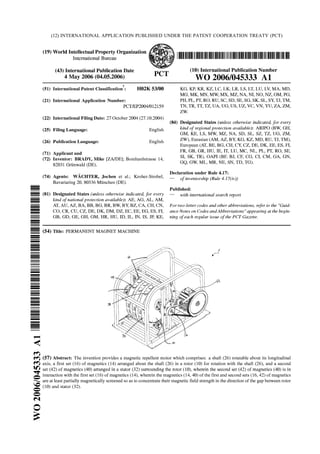
  • 1. (12) INTERNATIONAL APPLICATION PUBLISHED UNDER THE PATENT COOPERATION TREATY (PCT)
  • 2. WO 2006/045333 PCT/EP2004/012159 1 PERMANENT MAGNET MACHINE Field of the invention This invention relates to a magnetic repellent motor, or drive mechanism. Such a mechanism may be useful for driving an electrical generation means, a vehicle, a vessel, an aircraft or the like. Background to the invention Conventional power sources rely on fossil fuels or secondary power sources such as nuclear power or electricity derived by whatever means for its source of driving power. All of the above sources of power suffer from disadvantages such as being the cause of pollution, requiring transportation or transmission over long distances to the point of use, and being costly to purchase. Thus, there is a need for a power source which is substantially pollution-free to operate, requiring substantially no external power, and is simple to maintain. Summary of the invention The invention provides a magnetic repellent motor which comprises: a shaft rotatable about its longitudinal axis, a first set of magnetic sources arranged about the shaft in a rotor for rotation with the shaft, and a second set of magnetic sources arranged in a stator surrounding the rotor, wherein the second set of magnetic sources is in magnetic communication with the first set of magnetic sources, wherein the magnetic sources of the first and second sets of magnetic sources are at least partially magnetically screened so as to direct their magnetic field into a gap between the two sets of magnetic sources. Thus, the interaction of at least some of the magnetic sources of the first and second set urges the shaft to rotate.
  • 3. WO 2006/045333 PCT/EP2004/012159 2 The interaction may be the net repelling force of like magnetic poles repelling each other thereby urging the magnetic sources away from each other, however, since only the magnetic sources of the first set of magnetic sources are able to be displaced under the urging of the force, the shaft is urged to rotate into a position in which the repelling force is less. The rotor may be substantially disc shaped, and the first set of magnetic sources may be located in a peripheral region of the rotor which rotates together with the shaft. The stator may be in the form of a pair of arms, which co-operates with the corresponding rotor. The arms of a pair may be displaceable relative to each other a n d their corresponding rotor, such that a gap between the arms and the rotor may be selectively set. The gap may be set manually, for example by a hand wheel, or automatically, for example by a centrifugal distributed weights system, thereby to effect control over the rotational speed of the shaft, i.e. the smaller the gap the greater the repulsion forces between the magnetic sources of the rotor and the stator. The rotor may have a plurality of magnetic source receiving zones provided therein for receiving the magnetic sources of the first set of magnetic sources. The stator may have a plurality of magnetic source receiving zones provided therein for receiving the magnetic sources of the second set of magnetic sources. The receiving zones may be in the form of circumferentially extending spaced apart sockets. The sockets may be substantially cylindrical and may be arranged in a plane perpendicular to the longitudinal axis of the shaft.
  • 4. WO 2006/045333 PCT/EP2004/012159 3 The sockets may be angled at an acute angle relative to the tangent to the circumference of the rotor at the mouth opening of its sockets and to the inner circumference of the stator at the mouth opening of its sockets. This angle may be between 18 degrees and 40 degrees, preferably between 30 degrees to 35 degrees. The sockets may receive or incorporate a socket lining consisting at least partially of a magnetic screening material. The socket lining may line the entire extent of the sockets so that only the opening to the exterior remains unlined. The socket lining may comprise a shield of another magnetic screening material. The shield may envelop the entire extent of the socket lining so that only the opening to the exterior remains unlined. In another preferred embodiment, the shield covers a substantial percentage of the socket lining, e.g. 50% thereof. The magnetic sources may be Nd-fe-B magnets sized and dimensioned to snugly fit into the sockets and socket linings, respectively. The magnetic sources may be constituted by a 37mm diameter 75mm length cylindrical magnet having 360000 gauss. The socket lining, the shield and the magnetic sources may comprise through holes to receive a securing pin, preferably in a direction parallel to the longitudinal axis of the shaft. The number of sockets in the rotor and the corresponding stator may differ so that there is not a one to one relationship between the sockets in the rotor and the sockets in the corresponding stator. Likewise, the number of magnetic sources in the first and second sets may differ so that a proportion of the magnetic sources of the two sets are out of register at any given time. Some sockets may be empty i.e. without a magnetic source, in either the rotor or the stator, or in both.
  • 5. WO 2006/045333 PCT/EP2004/012159 4 The magnetic repellent motor may have one or more rotors and stators of the above type arranged in a stack. It is preferable for magnetic sources of adjacent rotors to be out of register i.e. staggered or offset relative to each other. Description of the drawings Without in any way limiting the scope of the invention, the invention will now be illustrated with reference to the accompanying drawings. Fig. 1 is a perspective view showing a rotor of the magnetic repellent motor according to the invention; Fig. 2 is a perspective view showing a stack of rotors of Fig. 1 in assembled arrangement; Fig. 3 is a perspective view showing a left arm of a stator of the magnetic repellent motor according to the invention; Fig. 4 is a perspective view showing a right arm of a stator of the magnetic repellent motor according to the invention; Fig. 5 is a perspective view showing a stack of stators of Fig. 3 and 4 in assembled arrangement; Fig 6 is a perspective view showing a socket lining of a stator or a rotor of the magnetic repellent motor according to the invention; Fig. 7 is a perspective view showing a magnetic source of the magnetic repellent motor according to the invention; and
  • 6. WO 2006/045333 PCT/EP2004/012159 5 Fig. 8 is a perspective view showing one embodiment of the magnetic repellent motor according to the invention coupled to an electrical generator. Description of preferred embodiments Referring to Fig. 1, a substantially disk-shaped rotor 10 is made of a non-magnetic material. The rotor 10 comprises a plurality of magnetic source receiving zones 12 provided therein for receiving magnetic sources 28 (shown in later figures) of a first set 16 of magnetic sources. The receiving zones 12 are in the form of circumferentially extending spaced apart and substantially cylindrical sockets 18 which are located in a plane perpendicular to the rotational axis of the rotor 10 in a peripheral region thereof. In the region of the sockets 18, the rotor 10 further comprises through holes 20 arranged in its side surfaces 22 and extending parallel to the rotational axis of the rotor 10. The rotor 10 further comprises a centre hole 24 for receiving a shaft 26 (shown in later figures). The sockets 18 are preferably angled at an acute angle relative to a tangent to the circumference of the rotor 10 at the mouth opening of the sockets 18. Preferably, this angle is between 18 and 40 degrees, more preferably between 30 a n d 35 degrees. In. one particularly preferred embodiment the angle is 34 degrees. A shown in Fig. 2, the sockets 18 receive (or incorporate) a socket lining 28 (shown in more detail in later figures) which is at least partially made of a magnetic screening non-metallic or metallic material, for example graphite. The socket lining 28 covers the entire extent of the sockets 18 so that only the opening to the exterior remains uncovered. In the rotor assembly 30 shown in Fig. 2, three rotors 10 have been stacked in a row on the shaft 26. The connection between the rotors 10 and the shaft 26 as well as the connection between the multiple rotors 10 can be established via linking means known in the art. In general, the magnetic repellent motor 1 may h a v e any
  • 7. WO 2006/045333 PCT/EP2004/012159 6 number of rotors 10 and corresponding stators 32, since the effect of operating several rotors 10 in parallel is accumulative. However, it may be useful for a smooth operation of the motor 1 to arrange the rotors 10 such that the magnetic sources of adjacent rotors 10 are staggered or offset relative to each other. Referring to Fig. 3 and 4, a stator 32 is depicted. The stator 32 is made of a non- magnetic material. The left arm 34 shown in Fig. 3 and the right arm 36 shown in Fig. 4 combine to form the stator 32. Each of the arms 34, 36 has a substantially semicircular shape and is adapted to enclose the corresponding rotor 10 in radial direction while still leaving a gap between the stator 32 and the rotor 10. The arms 34, 36 of one stator 32 are dispiaceabie relative to each other and their corresponding rotor 10 such that the gap between the arms 34, 36 and the rotor 10 may be selectively set. The stator 32 comprises a plurality of magnetic source receiving zones 38 provided therein for receiving magnetic sources 40 (shown in later figures) of a second set 42 of magnetic sources. The receiving zones 38 again are in the form of circumferentially extending spaced apart and substantially cylindrical sockets 44 which are located in a plane perpendicular to the longitudinal axis of the shaft 26. In the region of the sockets 44, the stator 32 comprises through holes 46 arranged in its side surfaces 48 and extending parallel to the longitudinal axis of the shaft 26. The sockets 44 are again preferably angled at an acute angle relative to a tangent to the inner circumference of the stator 32 at the mouth opening of the sockets 44. Preferably, this angle is between 18 and 40 degrees, more preferably between 30 and 35 degrees. The angle of the sockets 18 and 44 and the relative positioning between them has to be adjusted to allow for a good performance of the motor 1. Fig 5 shows a stator assembly consisting of three stators so as to fit to the rotor assembly of Fig. 2. As described with reference to the sockets 18 of Fig. 2, the sockets 44 receive (or incorporate) a socket lining 50 (shown in more detail in later figures) which is at least partially made of a magnetic screening non-metallic or
  • 8. WO 2006/045333 PCT/EP2004/012159 7 metallic material. The socket lining 50 covers the entire extent of the sockets 44 so that only the opening to the exterior remains uncovered. Referring to Fig. 6, a socket lining 28, 50 of the rotor 10 or the stator 32 is depicted in more detail. The socket lining 28, 50 is formed to fit into the sockets 18, 44 and may fully be made of a non metallic or a metallic material which has magnetic screening properties. In one preferred embodiment the socket lining 28, 50 is made of diamagnetic graphite and is partially surrounded by an additional shield 52 of a material having strong magnetic screening properties, e.g. stainless steel. In the embodiment shown in Fig. 6, the shield 52 surrounds about 5 0 % of the socket lining surface. Thus, by at least partially covering the sockets 18, 44 with a magnetic screening material the magnetic field of inserted magnetic sources 14, 40 is, so to say, focused axially with the socket 18, 44, rather than dissipated about the magnets. Further, through holes 54 are provided in the socket linings 28, 50 which correspond to through holes 20 and 46 in the rotor 10 and stator 32, respectively. Thus, a retaining pin 56 may be inserted after the magnetic source 14, 40 has been put in the socket 18, 44 to detachably fix the magnetic source 14, 40 to the socket lining 28, 50 and the socket 18, 44 so as to prevent expulsion of the magnetic sources 14, 40 during operation. Fig. 7 shows a typical magnetic source 14, 40 used in the motor 1 according to the invention. The magnetic sources 14, 40 may be natural magnets, induced magnets or electromagnets. The magnetic source for example is a Nd-fe-B magnet sized and dimensioned to snugly fit into the socket 18, 44 and socket lining 28, 50, respectively. In one preferred embodiment, the magnetic source 18, 44 is a substantially cylindrical shaped magnet and preferably has a diameter of 37mm, a length of 75mm and provides 360000 gauss. However, the magnetic source 18, 44 may be shaped differently than cylindrical and may comprise different characteristics. In any case, the magnetic source 18, 44 has to comprise an through hole 58 for receiving the retaining pin 56.
  • 9. WO 2006/045333 PCT/EP2004/012159 8 The magnetic repellent motor 1 of the example of Fig. 8 is mounted on a frame 60 and is coupled to an electrical generator 62. In this specific embodiment, the motor 1 comprises three rotors 10 of the above type which are mounted on a single rotating shaft 26 and work with three stators 32 of the above type to urge the shaft 26 to rotate about its longitudinal axis. The shaft 26 of the mechanism may be connected to a gearbox to obtain mechanical advantage. The stator arms can be moved e.g. by a stepper motor 62. The number of sockets in the rotors 10 and their corresponding stators 32 may differ such that there is not a one to one relationship between t h e sockets 18 in the rotor 10 and the sockets 44 in the corresponding stator 32. Likewise, the number of magnetic sources in the stator 32 and the rotor 10 may differ so that a proportion of the magnetic sources 14, 40 are out of register at any given time. Some sockets may be empty i.e. without a magnetic source, in either the rotor 10 or the stator 32, or both. The sockets 18 of the rotors 10 can be staggered i.e. offset relative to the sockets of adjacent rotors or they can line-up in register. Thus the magnetic repellent motor 1 may be time-tuned by the relative positioning of the magnetic sources 14 of adjacent rotors 10. Thus, the interaction of at least some of the magnetic sources 1 4, 40 of the first and second set 16, 42 urges the shaft 26 to rotate. Once the shaft 26 begins to rotate the plurality of simultaneous interactions causes the shaft 26 to continue rotating. As mentioned before, the magnetic repellent motor 1 may have any number of rotor 10 and stator 32 sets. Although the precise adjustment of t h e motor elements is important, one may imagine other embodiments covered by the invention according to the appended claims.
  • 10. WO 2006/045333 PCT/EP2004/012159 9 Claims 1. A magnetic repellent motor which comprises: a shaft (26) rotatable about its longitudinal axis, a first set (16) of magnetic sources (14) arranged about the shaft (26) in at least one rotor (10) for rotation with the shaft (26), and a second set (42) of magnetic sources (40) arranged in at least one stator (32) surrounding the rotor (10), wherein the second set (42) of magnetic sources (40) is in magnetic communication with the first set (16) of magnetic sources (14), wherein the magnetic sources (14, 40) of the first and second sets (16, 42) of magnetic sources are at least partially magnetically screened so as to direct their magnetic field into a gap between the two sets (16, 42) of magnetic sources. 2. The magnetic repellent motor according to claim 1, wherein the rotor (10) is substantially disc shaped, and the first set (16) of magnetic sources (14) are located in a peripheral region of the rotor (10) which rotates together with the shaft (26). 3. The magnetic repellent motor according to claim 1 or 2, wherein the stator (32) is formed as a pair of arms (34, 36), which co-operate with the corresponding rotor (10). 4. The magnetic repellent motor according to claim 3, wherein t h e two arms (34, 46) of a pair are displaceable relative to each other and to the corresponding rotor (10), such that a gap between the arms (34, 36) and the rotor (10) may be selectively set.
  • 11. WO 2006/045333 PCT/EP2004/012159 10 5. The magnetic repellent motor according to any one of the preceding claims, wherein the rotor (10) may have a plurality of magnetic source receiving zones (12) provided therein for receiving the magnetic sources (14) of the first set (16) of magnetic sources. 6. The magnetic repellent motor according to any one of the preceding claims, wherein the stator (32) may have a plurality of mag netic source receiving zones (38) provided therein for receiving the magnetic sources (40) of the second set (42) of magnetic sources. 7. The magnetic repellent motor according to any one of the preceding claims, wherein the receiving zones (12, 38) are formed as circumferentially extending spaced apart sockets (18, 44). 8. The magnetic repellent motor according to claim 7, wherein the sockets (18, 44) are substantially cylindrical and are arranged in a plane perpendicular to the longitudinal axis of the shaft (26). 9. The magnetic repellent motor according to claim 7 or 8, wherein the sockets (18, 44) are angled at an acute angle relative to the tangent to the circumference of the rotor (10) at the mouth opening of its sockets (18) and to the inner circumference of the stator (32) at the mouth opening of its sockets (44), respectively. 10. The magnetic repellent motor according to claim 9, wherein the angle is between 18 degrees and 40 degrees, preferably between 30 degrees and 35. 11. The magnetic repellent motor according to any o n e of claims 7 to 10, wherein the sockets (18, 44) comprise or receive a socket lining (28, 50) consisting at least partially of a magnetic screening material. 12. The magnetic repellent motor according to claim 1 1, wherein the socket lining (28, 50) may comprise a shield (52) of another magnetic screening
  • 12. WO 2006/045333 PCT/EP2004/012159 11 material, which covers a substantial extent of the socket lining, preferably about 50% thereof. 13. The magnetic repellent motor according to any one of t h e preceding claims, wherein the magnetic sources (14, 40) are Nd-fe-B magnets sized and dimensioned to snugly fit into the sockets (18, 44) a n d socket linings (28, 50), respectively. 14. The magnetic repellent motor according to any one of the preceding claims, wherein the magnetic sources (14, 40) are constituted by a 37mm diameter 75mm length cylindrical magnet providing 360000 gauss. 15. The magnetic repellent motor according to any one of claims 18 to 28, wherein the rotor (10) and stator (32), the socket lining (28, 50), and the magnetic sources (14, 40) comprise through holes (20, 46, 54, 58) to receive a retaining pin (56), preferably in a direction parallel to the longitudinal axis of the shaft (26). 16. The magnetic repellent motor according to any o n e of claims 7 to 15, wherein the number of sockets (18) in the rotor (10) filled with magnetic sources (14) and the number of sockets (44) in the corresponding stator (32) filled with magnetic sources (40) differ. 17. The magnetic repellent motor according to any one of the preceding claims, wherein it comprises a plurality of rotors (10) and stators (32) arranged in a stack. 18. The magnetic repellent motor according to claim 17, wherein the magnetic sources (14) of adjacent rotors (10) are staggered or offset relative to each other.
  • 13. WO 2006/045333 PCT/EP2004/012159 1/8
  • 14. WO 2006/045333 PCT/EP2004/012159 2/8
  • 15. WO 2006/045333 PCT/EP2004/012159 3/8
  • 16. WO 2006/045333 PCT/EP2004/012159 4/8
  • 17. WO 2006/045333 PCT/EP2004/012159 5/8
  • 18. WO 2006/045333 PCT/EP2004/012159 6/8
  • 19. WO 2006/045333 PCT/EP2004/012159 7/8
  • 20. WO 2006/045333 PCT/EP2004/012159 8/8
  • 21. Form PCT/ISA/210 (second sheet) (January 2004)