2. the İskenderpaşa historic masonry minaret. As in Figure 1, the minaret is very thin and tall
with one balcony on its body.
2012 A. C. Altunisik: Dynamic response of masonry minarets
¸
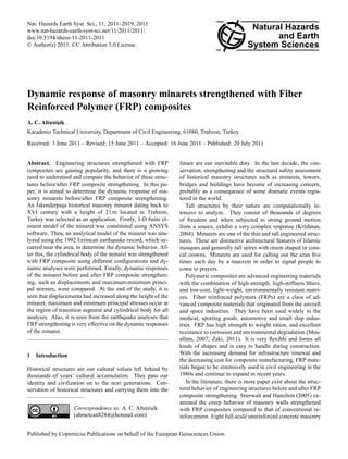
Figure 1 Some views of İskenderpaşa historical masonry minaret
Fig. 1. Some views of ˙
Iskenderpas, a historical masonry minaret
¸
walls were constructed for testing long-term deflections out- The objective of this paper is to calculate the detailed dy-
of-plane. Mosallam (2007) presented the results of a study namic responses of a historical masonry minaret and com-
Minaretsonbasicallytheconsist offlexural behavior of a pare thematoshaft, composite counterpart. The base is
focused evaluating out-of-plane three parts; base, an FRP and a gallery. For this pur-
two FRP composite systems for strengthening unreinforced ˙
pose, the Iskenderpasa masonry minaret located in the city
¸
foundation of the minaret. The shaft is pro- thin, slim bodyTurkey is selected as a and study. A are
red brick masonry walls. Ghosh and Karbhari (2007) the center of Trabzon, of the minaret case stairs
vided details of an investigation into the strengthening effi- three-dimensional finite element model of the minaret has
place cylindrically in
ciency of FRP- rehabilitated the shaftslabs through teststhe been created by ANSYS software and structural analysis has the
bridge deck to provide necessary structural support for highly
conducted on slab sections cut from a bridge just prior to been performed. Then, the cylindrical body of the minaret
elongated shafts. et al. (2008) conducted a balcony thatstrengthened with FRP upper section where the
demolition. Al-Saidy The gallery is an analytical was encircles the composite using different config-
parametric study on the behavior of steel-concrete compos- urations and dynamic analyses were performed. At the end
muezzins call out to prayer.
ite beam that has been strengthened with It is plates. In
CFRP covered of the a roof-likeresponses before and after FRP com-
by study, dynamic canopy and adorned with
addition, the effect of girder damage on the overall load dis- posite strengthening such as displacements and maximum-
ornamentationvarious load cases. Mortazaei bricksbeen decorated with painted tile, cornices, arches
such as decorative et al. (2010) minimum principal stresses are compared.
tribution of a typical short span composite bridge has
investigated for
and
and inscriptions. Similarofto near-fault groundtypi-
determine the seismic response
cal existing RC buildings subjected to
FRP strengthened
classical Ottoman style minarets, the İskenderpaşa minaret
mo- ˙
2 Iskenderpasa historical masonry minaret
¸
tions. Kim and Harries (2010) emerged a modeling approach
consist of thefooting of timber beams strengthened with The Iskenderpasa historical masonry minaret has a totalas a
to predict a behavior as a base; pulpit, transition segment, cylindrical or polygonal body
˙ ¸
FRP composites. A 3-D finite element analysis model is for- height of 20.5 m and is located in a heavy traffic and crowded
shaft; balcony; the orthotropic constitutive characteristics area in Trabzon citythe end ornament as shown in
mulated, based on upper part of the minaret body; spire; and center, Turkey. The minaret was built by
of timber species. Zaki (2011) studied the behavior of FRP a governor of a Trabzon (˙ Iskender Pasha) in the XVI century.
Figure 2. circular columns under combined axial loads Stones and bricks were used together in construction of the
strengthened
and biaxial bending moments. Tao et al. (2011) performed a minaret with beautiful decorations under the balcony. Scare-
series of laboratory tests investigating the behavior of a large crows are decorated with emblems and circular motifs. Fig-
model masonry arch bridge repaired with externally bonded ure 1 shows some views of the ˙ Iskenderpasa historic masonry
¸
FRP composites on its intrados. A two-span, single-ring minaret. As in Fig. 1, the minaret is very thin and tall with
semi-circular brick arch bridge was selected for this study, one balcony on its body.
complete with fill material. Besides these studies, there 5/19 Minarets basically consist of three parts; a base, a shaft,
is
not more paper exist only a few paper (not enough for liter- and a gallery. The base is foundation of the minaret. The
ature) exist relate to dynamic responses of FRP strengthened shaft is the thin, slim body of the minaret and stairs are place
thin and tall historical masonry structures such as minarets. cylindrically in the shaft to provide the necessary structural
Nat. Hazards Earth Syst. Sci., 11, 2011–2019, 2011 www.nat-hazards-earth-syst-sci.net/11/2011/2011/
3. A. C. Altunisik: Dynamic response of masonry minarets
¸ 2013
Figure 2 Segments of the classical Ottoman style and İskenderpaşa minarets
General arrangement drawings of the entire minaret are shown in Figure 3 where the
geometrical properties of the minaret are given. In addition to these dimensions, there is a
0.20m diameter stone block in the middle of the minaret. Around the stone block, there are
83 stairs from the floor to the balconyOttoman style andheight. Each stair has an inner and
Figure 2 Segments of the classical with 0.20m step İskenderpaşa minarets
Fig. 2. Segments of the classical Ottoman style and ˙
Iskenderpasa minarets.
¸
outer radius as 0.10m and 0.60m, respectively.
General arrangement drawings of the entire minaret are shown in Figure 3 where the
geometrical properties of the minaret are given. In addition to these dimensions, there is a
0.20m diameter stone block in the middle of the minaret. Around the stone block, there are
83 stairs from the floor to the balcony with 0.20m step height. Each stair has an inner and
outer radius as 0.10m and 0.60m, respectively.
Figure 3 Geometrical properties of the minaret
Fig. 3. Geometrical properties of the minaret.
support for the elongated shafts. The gallery is a balcony General arrangement drawings of the entire minaret are
6/19
that encircles the upper section where the muezzins call out shown in Fig. 3 where the geometrical properties of the
to prayer. It is covered by a roof-like canopy and adorned minaret are given. In addition to these dimensions, there is
with ornamentation such as decorative bricks and decorated
Figure 3 Geometrical properties of m diameter stone block in the middle of the minaret.
a 0.20 the minaret
with painted tile, cornices, arches and inscriptions. Similar Around the stone block, there are 83 stairs from the floor to
to classical Ottoman style minarets, the ˙
Iskenderpasa minaret
¸ the balcony with 0.20 m step height. Each stair has an inner
consisting of a footing as a base; pulpit, transition segment, and outer radius of 0.10 m and 0.60 m, respectively.
cylindrical or polygonal body as a shaft; balcony; upper part
6/19
of the minaret body; spire; and the end an ornament, as
shown in Fig. 2.
www.nat-hazards-earth-syst-sci.net/11/2011/2011/ Nat. Hazards Earth Syst. Sci., 11, 2011–2019, 2011
4. the SOLID186 element is shown in Figure 4. When the structural solid geometry property
of the SOLID186 element is examined, it can be seen that the elements appear to be made
2014 of tetrahedral, pyramid or prism options in the finiteA. C. Altunisik: Dynamicof the minaret.
element mesh model response of masonry minarets
¸
Figure 4 A schematic view and properties of the SOLID186 element
Fig. 4. A schematic view and properties of the SOLID186 element.
Table 1. Material properties used in analyses of the minaret.
Elements Material Properties
Directional Modulus of Elasticity Poisson’s Ratio Mass per unit Shear Modulus
Symmetry Type (N m−2 ) Vol. (kg m−3 ) (N m−2 )
7/19
Minaret Isotropic 2.00E9
total thickness of the FRP is chosen as 6 mm. Element stiffness behavior is considered as
0.20 2169 –
FRP Composite Orthotropic 3.3E10 0.25 1790 1.32E10
tensile and compressive. Extra displacement shapes are included, but extra stress outputs
are not considered.
3 Finite element modeling
Three-dimensional finite element models of the minaret be-
fore and after FRP composites strengthening were developed
using the ANSYS software (ANSYS, 2008). This program
can be used for linear and non-linear, static and dynamic
analyses of 3-D model structures. In this paper, based on its
physical and mechanical properties, the program was used
to determine the dynamic behavior of the minaret. Conver-
gence studies about element size were performed and the op-
timum element sizes were chosen for both models. In the
finite element models of the minaret, SOLID186 elements
were used which exhibited quadratic displacement behavior.
The element had 20 node and three degrees of freedom per
a) Before strengthened b) After strengthened c) Stone block and stairs node: translations in the nodal x, y, and z directions. In addi-
Figure 5 3D finite element models of the minaret before and after FRP composite tion, it had the capability of plasticity, elasticity, creep, stress
strengthened including concrete block and stairs
Fig. 5. 3-D finite element models of the minaret before and after stiffening, large deflection, and large strains. A schematic
FRP composite strengthening including concrete blockFRP composite
A total of 7 natural frequencies of the minaret before and after and stairs view of the SOLID186 element is shown in Fig. 4. When
strengthening were obtained with a range between 1.09-12.16 Hz and 1.61-19.07 Hz, the structural solid geometry property of the SOLID186 ele-
respectively. When the first seven modes are examined for both analyses, the first four ment is examined, it can be seen that the elements appear to
modes of the minaret are horizontal modes in the z and x directions, the fifth mode is a
torsional mode and last two modes are horizontal modes in the z and x directions as seen in
Nat. Hazards Earth Syst. Sci., 11, 2011–2019, 2011
Figure 6.
www.nat-hazards-earth-syst-sci.net/11/2011/2011/
5. A. C. Altunisik: Dynamic response of masonry minarets
¸ 2015
1st Mode 2nd Mode 3rt Mode 4th Mode 5th Mode 6th Mode 7th Mode
f1=1.09 Hz f2=1.09 Hz f3=5.59 Hz f4=5.59 Hz f5=9.78 Hz f6=12.16 Hz f7=12.16 Hz
a) Before FRP composite strengthening
4. DYNAMIC RESPONSE OF THE MINARET
Linear transient analyses of the İskenderpaşa historical masonry minaret before and after
FRP composite strengthening were performed using ERZIKAN/ERZ-NS component of
1992 Erzincan earthquake (Mw=6.9) ground motion (Figure 7) (PEER, 2007). The element
matrices were computed using the Gauss numerical integration technique (Bathe, 1996).
The Newmark method was used in the solution of the equations of motion.
Rayleigh damping constants were calculated nd
st between the first rthorizontal modethof the
1 Mode 2 Mode 3 Mode 4 Mode 5th Mode 6th Mode 7th Mode
minaret and the seventh mode, =1.61 Hz a 5%2=1.61 Hzratio. Alpha andHz coefficientsHz
f1 assuming f damping f3=10.59 Beta f4=10.61 f5=17.73 Hz f6=19.06 Hz f7=19.07 Hz
before and after FRP composite strengthened were calculated as 0.616 and 0.00146; 0.928
b) After FRP composite strengthening
and 0.00082, respectively. Because of the large memory required for the analyses, only the
Figure 6 Natural frequencies and corresponding mode shapes of the minaret before and
first 6.5 second of the frequencies and corresponding mode shapeswas the minaret before and after FRP composite strengthening.
Fig. 6. Natural ground motions, which is the effective duration, of taken into
after FRP composite strengthening
account in the calculations.
6.0 analysis is very important for thin and tall structures such
Acceleration (m/s²)
Max=0.515g
3.0
as minarets. But, removing test samples from the histori-
cal masonry structures such as minarets was not allowed by
0.0
the related institution. So, initial material properties were
-3.0
taken from the literature (Frunzio et al., 2001; Doang¨ n et
u
-6.0 al., 2006; Gentile and Saisi, 2007; Bayraktar et al., 2008;
0 1 2 3 4 5 6 7 8 9 10 11 12 13
Time (s) Bayraktar et al., 2009). For the structural strengthening of
Figure 7 The time-history of ground motion acceleration of 1992 Erzincan earthquake the minaret, woven carbon fiber fabric material was used.
Fig. 7. The time-history of ground motion acceleration of 1992 10/19 This material can be used for strengthening of reinforced
Erzincan. earthquake.
The horizontal displacements along to the height of the minaret at the time of maximum
concrete and masonry structures, brickwork and timber in
case of flexural and shear load due to increase of loading
response before and after FRP composite strengthened are given in Figure 8. It is seen that
capacity, changes of building utilisation, repair of defects,
the displacements increase along the height of the minaret and that the maximum
be made of tetrahedral, pyramid or prism options in the finite prevention of defects caused by earthquakes and meeting of
displacement (at mesh model of the minaret.
element the top of the minaret) is obtained before and after FRP composite changed standards. The values of the material properties
strengthened as 32.84 and 12.71 material properties and boundary condi-
Determination of cm, respectively. Also, the time histories of the horizontal used in analyses of the minaret are given in Table 1. The
displacements (withmust be taken into account cm for both analyses at the top of minaret was taken in place rock soil. As initial boundary
tions that a peak value of) 32.84 cm and 12.71 in the finite element
the İskenderpaşa historical masonry minaret subjected to the Erzincan ground motion is
presented in Figure 9.
www.nat-hazards-earth-syst-sci.net/11/2011/2011/ Nat. Hazards Earth Syst. Sci., 11, 2011–2019, 2011
11/19
6. 2016 A. C. Altunisik: Dynamic response of masonry minarets
¸
21 A total of 7 natural frequencies of the minaret before
and after FRP composite strengthening were obtained with
a range between 1.09–12.16 Hz and 1.61–19.07 Hz, respec-
tively. When the first seven modes were examined for both
14 analyses, the first four modes of the minaret are horizontal
Height (m)
modes in the z and x directions, the fifth mode is a torsional
21 mode and last two modes are horizontal modes in the z and
x directions, as seen in Fig. 6.
7
14
Height (m)
Before Strengthened 4 Dynamic response of the minaret
After Strengthened
Linear transient analyses of the ˙Iskenderpasa historical ma-
¸
0 7
0 9 18 27 36 sonry minaret before and after FRP composite strength-
Displacements Strengthened
Before (cm) ening were performed using ERZIKAN/ERZ-NS compo-
Figure 8 Variation of maximum displacements After Strengthened
along to the height of the minaret at the nent of 1992 Erzincan earthquake (Mw = 6.9) ground mo-
0
time of maximum response before and after FRP composite strengthened
Fig. 8. Variation of maximum displacements along to the height of
0 9 18 27 36 tion (Fig. 7) (PEER, 2007). The element matrices were
Displacements (cm)
the minaret at the time of maximum response before and after FRP computed using the Gauss numerical integration technique
40 composite strengthening. displacements along to the height of the minaret at the
Figure 8 Variation of maximum 40 (Bathe, 1996). The Newmark method was used in the solu-
time of maximum response before and after FRP composite strengthened
tion of the equations of motion.
40 40 Rayleigh damping constants were calculated between the
Displacements (cm)
(cm)
20 20
first horizontal mode of the minaret and the seventh mode,
Displacements
Displacements (cm)
Displacements (cm)
20 20
assuming a 5 % damping ratio. Alpha and Beta coefficients
0 0
before and after FRP composite strengthening were calcu-
0 0
lated as 0.616 and 0.00146; 0.928 and 0.00082, respectively.
-20 -20
-20
-20
Because of the large memory required for the analyses, only
the first 6.5 second of the ground motions, which is the ef-
Max=32.84cm
Max=32.84cm Max=12.71cmfective duration, was taken into account in the calculations.
Max=12.71cm
-40 -40 -40
-40
0.0 1.6 3.3 4.9 6.5 0.0 1.6 3.3 4.9 6.5
0.0 1.6 3.3 Time (s)
4.9 6.5 0.0 1.6 (s) 3.3
Time 4.9 6.5 The horizontal displacements along to the height of the
Time (s) Time (s) minaret at the time of maximum response before and af-
Figure 9 Time histories of maximum displacements at the top of minaret for both analyses
Figure 9 Time 9. Timeof maximum displacements at the top of minaret for both analyses FRP composite strengthening are given in Fig. 8. It
Fig. histories histories of maximum displacements at the top of ter
Figure 10 for both the contours of maximum horizontal displacement corresponding to
minaret points out analyses. is seen that the displacements increase along the height of
both analyses. These displacement contours represent the distribution of the peak values
Figure 10 points out the contours of maximum horizontal displacement corresponding to
the minaret and that the maximum displacement (at the top
reached by the maximum displacement at each point within the section. of the minaret) is obtained before and after FRP composite
both analyses. These displacement degrees represent the distribution of the peak values
conditions, all of the contours of freedom under the footing strengthening as 32.84 and 12.71 cm, respectively. Also, the
reached by the maximum displacement at each as fixed. the section.
part of the minaret are selected point within time histories of the horizontal displacements (with a peak
The 3-D finite element models of the minaret before and value of) 32.84 cm and 12.71 cm for both analyses at the top
after FRP composite strengthening including concrete block of the ˙
Iskenderpasa historical masonry minaret subjected to
¸
and stairs are shown in Fig. 5. According to the convergence
12/19 the Erzincan ground motion are presented in Fig. 9.
studies, the optimum mesh size is chosen as 30 cm and 20 cm Figure 10 points out the contours of maximum horizon-
before and after FRP composite strengthening, respectively. tal displacement corresponding to both analyses. These dis-
The mesh size may be reduced. But, when the element and placement contours represent the distribution of the peak val-
12/19
node numbers are increased, the analyses duration and to- ues reached by the maximum displacement at each point
tal volume increase. In the FRP composite strengthening within the section.
model, the thickness of FRP is very small when compared The time histories of the maximum and minimum prin-
with the thickness of cylindrical body of the minaret. Thus, cipal stresses of the minaret subjected to the Erzincan 1992
20 cm mesh size is used in the finite element analyses after earthquake are plotted in Fig. 11. As shown in Fig. 11, the
FRP composite strengthening. Therefore, 18620 and 95841 highest maximum and minimum principle stresses occurred
SOLID186 elements are used in the finite element models. before FRP composite strengthening. Also, maximum and
In the composite strengthening model, the cylindrical body minimum principal stress contours of the minaret before and
of the minaret is wrapped by four layers of FRP and total after FRP composite strengthening are given in Figs. 12 and
thickness of the FRP is chosen as 6 mm. Element stiffness 13. These stress contours represent the distribution of the
behavior is considered as tensile and compressive. Extra dis- peak values reached by the maximum principal stress at each
placement shapes are included, but extra stress outputs are point within the section. It is clearly seen from Figs. 12
not considered. and 13 that FRP composite is very effective in the principal
stresses.
Nat. Hazards Earth Syst. Sci., 11, 2011–2019, 2011 www.nat-hazards-earth-syst-sci.net/11/2011/2011/
7. a) Before FRP composite
A. C. Altunisik: Dynamic response of masonry minarets
¸ strengthened 2017
The time histories of the maximum and minimum principal stresses of the minaret
subjected to Erzincan 1992 earthquake are plotted in Figure 11. As shown in Figure 11, the
a) Before FRP composite b) After FRP composite
strengthened
highest maximum and minimum principle stresses occur before FRP composite strengthened
strengthened. Also, maximum and minimum principal stress contours of the minaret before
and after FRP composite strengthened are given in Figures 12 and 13. These stress
Figure 10 Maximum displacement contours of İskenderpaşa historical minaret
contours represent the distribution of the peak values reached by the maximum principal
˙
Fig. 10.each point within the section. It is clearly seen from Figures 12 anda13 that FRP minaret.
Maximum displacement contours of Iskenderpas historical ¸
stress at
composite is very effective in the principal stresses. 13/19
8 – From the modal analyses of the minaret, a total of
Minimum Principal Stress (MPa)
Maximum Principal Stress (MPa)
Max=6.90 MPa
0
7 natural frequencies before and after FRP compos-
6
-2 ite strengthening were obtained with a range between
4 1.09–12.16 Hz and 1.61–19.07 Hz, respectively. When
-4 the first seven modes are examined for both analyses,
2
the first four and last two modes are horizontal modes
-6
0
in the z and x directions and the fifth mode is a torsional
Min=6.77 MPa
b) After FRP composite -8 mode. It is seen that FRP composite brought stiffness
0.0 1.6
strengthened 3.3 4.9 6.5 0.0 1.6 3.3 4.9 6.5 into the structural system.
Time (s) Time (s)
(a) Before FRP composite strengthened
8 Figure 10 Maximum displacement contours of İskenderpaşa historical minaret – Rayleigh damping constants are calculated between the
Minimum Principal Stress (MPa)
Maximum Principal Stress (MPa)
Max=4.95 MPa
0 first horizontal mode of the minaret and the seventh
6
-2
mode, assuming a 5 % damping ratio. Alpha and Beta
13/19 coefficients before and after FRP composite strength-
4
-4 ening are calculated as 0.616 and 0.00146; 0.928 and
2 0.00082, respectively.
-6
0
Min=4.85 MPa – An earthquake analysis of the minaret before and after
-8
0.0 1.6 3.3 4.9 6.5 0.0 1.6 3.3 4.9 6.5 FRP composite strengthening was performed using the
Time (s) Time (s)
(b) After FRP composite strengthened 1992 Erzincan ground motion. It can be seen from the
Figure 11 The time histories of maximum and minimum principal stresses of İskenderpaşa analysis that horizontal displacements increased along
historical minaret before and after FRP composite strengthened to the height of the minaret for both analyses and that
Fig. 11. The time histories of maximum and minimum principal
stresses of the ˙
Iskenderpasa historical minaret before and after FRP
¸ the maximum displacement (at the top of the minaret)
composite strengthening. 14/19
was obtained before and after FRP composite strength-
ening as 32.84 and 12.71 cm, respectively.
– Maximum and minimum principal stresses occurred at
5 Conclusions
the region between the transition segment and the cylin-
drical body before FRP composite strengthening, and
This paper aimed to determine the dynamic response of ma- they are equal to 6.90 and −6.77 MPa, respectively.
sonry minarets before and after FRP composite strengthen- Therefore, it is likely that probable damages and cracks
ing. The ˙ Iskenderpasa historical masonry minaret with a
¸ due to earthquake loads can occur at the region between
height of 21 m located in Trabzon, Turkey was selected as the transition segment and the cylindrical body.
an application. A 3-D finite element model of the minaret
was constituted using ANSYS software and dynamic behav- – To eliminate the probable damages and cracks, the
ior was determined using 1992 Erzincan earthquake record cylindrical body of the minaret was strengthened with
before and after the FRP composite strengthening. The fol- FRP composite and dynamic analyses were performed.
lowing observations can be deduced from the study: FRP can be applied to the circular surfaces. The pulpit
www.nat-hazards-earth-syst-sci.net/11/2011/2011/ Nat. Hazards Earth Syst. Sci., 11, 2011–2019, 2011
8. 2018 A. C. Altunisik: Dynamic response of masonry minarets
¸
a) Maximum
a) Maximum principal stressess
principal stressess
b) Minimum
principal stressess b) Minimum
Figure 12 Maximum and minimum principal stress contours of İskenderpaşa historical stressess
principal
minaret obtained before FRP composite strengthened Figure 13 Maximum and minimum principal stress contours of İskenderpaşa histori
Fig. 12. Maximum and minimum principal stress contours of
the ˙Iskenderpasa historical minaret obtained before FRP compos-
¸ minaret obtained after FRP composite strengthened
Fig. 13. Maximum and minimum principal stress contours of
ite strengthening the ˙
Iskenderpasa historical minaret obtained after FRP composite
¸
15/19 strengthening
16/19
has a polygon surfaces and the transition segment has a lation, FRP composite strengthening should be consid-
variable polygon surfaces. So, only the cylindrical body ered and the responses should be compared before the
of the minaret was wrapped by FRP. From the analyses, FRP composite strengthening.
it is seen that maximum and minimum principal stresses
were obtained as 4.95 and −4.85 MPa, respectively.
Edited by: M. E. Contadakis
– It is seen from the study that FRP composite strength- Reviewed by: two anonymous referees
ening is very effective in the dynamic response of the
historical minaret. To determine the static, dynamic,
linear and nonlinear structural behavior of the histori-
cal masonry structures such as bridges, minarets, bell-
towers, dams, buildings, which are our cultural values
that left behind by thousands of years’ cultural accumu-
Nat. Hazards Earth Syst. Sci., 11, 2011–2019, 2011 www.nat-hazards-earth-syst-sci.net/11/2011/2011/
9. A. C. Altunisik: Dynamic response of masonry minarets
¸ 2019
References Kim, Y. J. and Harries, K. A.: Modeling of timber beams strength-
ened with various CFRP composites, Eng. Struct., 32, 3225–
Al-Saidy, A. H., Klaiber, F. W., Wipf, T. J., Al-Jabri, K. S., and 3234, doi:10.1016/j.engstruct.2010.06.011, 2010.
Al-Nuaimi, A. S.: Parametric study on the behavior of short Krishnan, S.: Three-dimensional nonlinear analysis of tall irregular
span composite bridge girders strengthened with carbon fiber steel buildings subject to strong ground motion, Ph. D Thesis,
reinforced polymer plates, Constr. Build. Mater., 22, 729–737, California Institute of Technology, 2004.
doi:10.1016/j.conbuildmat.2007.01.020, 2008. Mortezaei, A., Ronagh, H. R., and Kheyroddin, A.: Seismic eval-
ANSYS V10.1.3.: Swanson Analysis System, Pennsylvania, US, uation of FRP strengthened RC buildings subjected to near-fault
2008. ground motions having fling step, Compos. Struct., 92, 1200–
Bathe, K. J.: Finite Element Procedures in Engineering Analysis, 1211, doi:10.1016/j.compstruct.2009.10.017, 2010.
Englewood Cliffs, New Jersey, Prentice-Hall, 1996. Mosallam, A. S.: Out-of-plane flexural behavior of unreinforced
Bayraktar, A, Altunisik, A. C., Sevim, B., T¨ rker T, and Akk¨ se
¸ u o red brick walls strengthened with FRP composites, Compos. Part
M, Coskun, N.: Modal Analysis, Experimental Validation and
¸ B-Eng., 38, 559–574, doi:10.1016/j.compositesb.2006.07.019,
Calibration of a Historical Masonry Minaret, J. Test. Eval., 36, 2007.
516–524, doi:10.1520/JTE101677, 2008. PEER (Pacific Earthquake Engineering Research Centre): http:
Bayraktar, A., Birinci, F., Altunisik, A. C., T¨ rker, T, and Sevim,
¸ u //peer.berkeley.edu/smcat/search.html, 2011.
B.: Finite Element Model Updating of Senyuva Historical Arch Stierwalt, D. D. and Hamilton, H. R.: Creep of concrete masonry
Bridge using Ambient Vibration Tests, Balt. J. Road Bridge E., walls strengthened with FRP composites. Constr. Build. Mater.,
4, 177–185, doi:10.3846/1822-427X.2009.4.177-185, 2009. 19, 181–187, doi:10.1016/j.conbuildmat.2004.07.001, 2005.
g u g ¨ I.:
Do˘ ang¨ n, A., Acar, R., Livao˘ lu, R., and Tuluk, O˙ Performance Tao, Y., Stratford, T. J., and Chen, J. F.: Behavior of a masonry arch
of masonry minarets against earthquakes and winds in Turkey, bridge repaired using fibre-reinforced polymer composites, Eng.
1st International Conference on Restoration of Heritage Masonry Struct., 33, 1594–1606, doi:10.1016/j.engstruct.2011.01.029,
Structures, Cairo, Egypt, 2006. 2011.
Frunzio, G., Monaco, M., and Gesualdo, A.: 3-D FEM analysis of Zaki, M. K.: Investigation of FRP strengthened circular
a Roman Arch Bridge, Historical Constructions, 591–598, 2001. columns under biaxial bending, Eng. Struct., 33, 1666–1679,
Gentile, C. and Saisi, A.: Ambient vibration testing of his- doi:10.1016/j.engstruct.2011.02.003, 2011.
toric masonry towers for structural identification and dam-
age assessment, Constr. Build. Mater., 21, 1311–1321,
doi:10.1016/j.conbuildmat.2006.01.007, 2007.
Ghosh, K. K. and Vistasp, M. K.: Evaluation of strength-
ening through laboratory testing of FRP rehabilitated bridge
decks after in-service loading, Compos. Struct., 77, 206–222,
doi:10.1016/j.compstruct.2005.07.014, 2007.
www.nat-hazards-earth-syst-sci.net/11/2011/2011/ Nat. Hazards Earth Syst. Sci., 11, 2011–2019, 2011