6161103 7.3 relations between distributed load, shear and moment
1. 7.3 Relations between Distributed
Load, Shear and Moment
Distributed Load
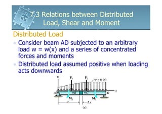
Consider beam AD subjected to an arbitrary
load w = w(x) and a series of concentrated
forces and moments
Distributed load assumed positive when loading
acts downwards
2. 7.3 Relations between Distributed
Load, Shear and Moment
Distributed Load
A FBD diagram for a small
segment of the beam having a
length ∆x is chosen at point x
along the beam which is not
subjected to a concentrated force
or couple moment
Any results obtained will not apply
at points of concentrated loadings
3. 7.3 Relations between Distributed
Load, Shear and Moment
Distributed Load
The internal shear force and bending
moments shown on the FBD are
assumed to act in the positive sense
Both the shear force and moment
acting on the right-hand face must
be increased by a small, finite
amount in order to keep the
segment in equilibrium
4. 7.3 Relations between Distributed
Load, Shear and Moment
Distributed Load
The distributed loading has been replaced by a
resultant force ∆F = w(x) ∆x that acts at a
fractional distance k (∆x) from the right end,
where 0 < k <1
+ ↑ ∑ Fy = 0;V − w( x)∆x − (V + ∆V ) = 0
∆V = − w( x)∆x
∑ M = 0;−V∆x − M + w( x)∆x[k (∆x )] + ( M + ∆M ) = 0
∆M = V∆x − w( x)k (∆x) 2
5. 7.3 Relations between Distributed
Load, Shear and Moment
Distributed Load
dV
= −w(x)
dx
Slope of the = Negative of
shear diagram distributed load intensity
dM
=V
dx
Slope of = Shear moment diagram
6. 7.3 Relations between Distributed
Load, Shear and Moment
Distributed Load
At a specified point in a beam, the slope of the
shear diagram is equal to the intensity of the
distributed load
Slope of the moment diagram = shear
If the shear is equal to zero, dM/dx = 0, a point
of zero shear corresponds to a point of maximum
(or possibly minimum) moment
w (x) dx and V dx represent differential area
under the distributed loading and shear diagrams
7. 7.3 Relations between Distributed
Load, Shear and Moment
Distributed Load
∆VBC = − ∫ w( x)dx
Change in = Area under
shear shear diagram
∆M BC = ∫ Vdx
Change in = Area under
moment shear diagram
8. 7.3 Relations between Distributed
Load, Shear and Moment
Distributed Load
Change in shear between points B and C is
equal to the negative of the area under the
distributed-loading curve between these
points
Change in moment between B and C is equal
to the area under the shear diagram within
region BC
The equations so not apply at points where
concentrated force or couple moment acts
9. 7.3 Relations between Distributed
Load, Shear and Moment
Force
FBD of a small segment of
the beam
+ ↑ ∑ Fy = 0; ∆V = − F
Change in shear is negative
thus the shear will jump
downwards when F acts
downwards on the beam
10. 7.3 Relations between Distributed
Load, Shear and Moment
Force
FBD of a small segment of the
beam located at the couple
moment
∑ M = 0; ∆M = M O
Change in moment is positive
or the moment diagram will
jump upwards MO is clockwise
11. 7.3 Relations between Distributed
Load, Shear and Moment
Example 7.9
Draw the shear and moment diagrams for the
beam.
12. 7.3 Relations between Distributed
Load, Shear and Moment
Solution
Support Reactions
FBD of the beam
13. 7.3 Relations between Distributed
Load, Shear and Moment
Solution
Shear Diagram
V = +1000 at x = 0
V = 0 at x = 2
Since dV/dx = -w = -500, a straight negative sloping
line connects the end points
14. 7.3 Relations between Distributed
Load, Shear and Moment
Solution
Moment Diagram
M = -1000 at x = 0
M = 0 at x = 2
dM/dx = V, positive yet linearly decreasing from
dM/dx = 1000 at x = 0 to dM/dx = 0 at x = 2
15. 7.3 Relations between Distributed
Load, Shear and Moment
Example 7.10
Draw the shear and moment diagrams for the
cantilevered beam.
16. 7.3 Relations between Distributed
Load, Shear and Moment
Solution
Support Reactions
FBD of the beam
17. 7.3 Relations between Distributed
Load, Shear and Moment
Solution
At the ends of the beams,
when x = 0, V = +1080
when x = 2, V = +600
Uniform load is downwards and slope of
the shear diagram is constant
dV/dx = -w = - 400 for 0 ≤ x ≤ 1.2
The above represents a change in shear
18. 7.3 Relations between Distributed
Load, Shear and Moment
Solution
∆V = − ∫ w( x)dx = −400(1.2) = −480
V x =1.2
=V x =0
+ (−480) = 1080 − 480 = 600
Also, by Method of Sections, for equilibrium,
V = +600
Change in shear = area under the load
diagram at x = 1.2, V = +600
19. 7.3 Relations between Distributed
Load, Shear and Moment
Solution
Since the load between 1.2 ≤ x ≤ 2, w =
0, slope dV/dx = 0, at x = 2, V = +600
Shear Diagram
20. 7.3 Relations between Distributed
Load, Shear and Moment
Solution
At the ends of the beams,
when x = 0, M = -1588
when x = 2, M = -100
Each value of shear gives the slope of the
moment diagram since dM/dx = V
at x = 0, dM/dx = +1080
at x = 1.2, dM/dx = +600
For 0 ≤ x ≤ 1.2, values of the shear diagram are
positive but linearly increasing
21. 7.3 Relations between Distributed
Load, Shear and Moment
Solution
Moment diagram is parabolic with a linearly
decreasing positive slope
Moment Diagram
22. 7.3 Relations between Distributed
Load, Shear and Moment
Solution
Magnitude of moment at x = 1.2 = -580
Trapezoidal area under the shear diagram =
change in moment
∆M = ∫ Vdx
1
= 600(1.2) + (1080 − 600)(1.2) = +1008
2
M x =1.2 = M x =0 + 1008
= −1588 + 1008 = −580
23. 7.3 Relations between Distributed
Load, Shear and Moment
Solution
By Method of Sections,
at x = 1.2, M = -580
Moment diagram has a constant slope for 1.2 ≤
x ≤ 2 since dM/dx = V = +600
Hence, at x = 2, M = -100
24. 7.3 Relations between Distributed
Load, Shear and Moment
Example 7.11
Draw the shear and moment diagrams for the
shaft. The support at A is a thrust bearing
and the support at B is a journal bearing.
25. 7.3 Relations between Distributed
Load, Shear and Moment
Solution
Support Reactions
FBD of the supports
26. 7.3 Relations between Distributed
Load, Shear and Moment
Solution
At the ends of the beams,
when x = 0, V = +3.5
when x = 8, V = -3.5
Shear Diagram
27. 7.3 Relations between Distributed
Load, Shear and Moment
Solution
No distributed load on the shaft, slope dV/dx = -
w=0
Discontinuity or “jump” of the shear diagram at
each concentrated force
Change in shear negative when the force acts
downwards and positive when the force acts
upwards
2 kN force at x = 2m changes the shear from
3.5kN to 1.5kN
3 kN force at x = 4m changes the shear from
1.5kN to -1.5kN
28. 7.3 Relations between Distributed
Load, Shear and Moment
Solution
By Method of Sections, x = 2m and V =
1.5kN
29. 7.3 Relations between Distributed
Load, Shear and Moment
Solution
At the ends of the beams,
when x = 0, M = 0
when x = 8, M = 0
Moment Diagram
30. 7.3 Relations between Distributed
Load, Shear and Moment
Solution
Area under the shear diagram = change in
moment
∆M = ∫ Vdx = 3.5(2) = 7
M x=2
=M x =0
+7 = 0+7 = 7
Also, by Method of Sections,
x = 2m, M = 7 kN .m
31. 7.3 Relations between Distributed
Load, Shear and Moment
Example 7.12
Draw the shear and moment diagrams for the
beam.
32. 7.3 Relations between Distributed
Load, Shear and Moment
Solution
Support Reactions
FBD of the beam
33. 7.3 Relations between Distributed
Load, Shear and Moment
Solution
At A, reaction is up,
vA = +100kN
No load acts between A and C so shear remains
constant, dV/dx = -w(x) = 0
600kN force acts downwards, so the shear jumps
down 600kN from 100kN to -500kN at point B
No jump occur at point D where the 4000kN.m
coupe moment is applied since ∆V = 0
34. 7.3 Relations between Distributed
Load, Shear and Moment
Solution
Shear Diagram
Slope of moment from A to C is constant
since dM/dx = V = +100
36. 7.3 Relations between Distributed
Load, Shear and Moment
Solution
Determine moment at C by Method of Sections
where MC = +1000kN or by computing area
under the moment
∆MAC = (100kN)(10m) = 1000kN
37. 7.3 Relations between Distributed
Load, Shear and Moment
Solution
Since MA = 0, MC = 0 + 1000kN.m = 1000kN.m
From C to D, slope, dM/dx = V = -500
For area under the shear diagram between C and
D, ∆MCD = (-500kN)(5m) = -2500kN, so that MD
= MC + ∆MCD = 1000 – 2500 = -1500kN.m
Jump at point D caused by concentrated couple
moment of 4000kN.m
Positive jump for clockwise couple moment
38. 7.3 Relations between Distributed
Load, Shear and Moment
Solution
At x = 15m, MD = - 1500 + 4000 = 2500kN.m
Also, by Method of Sections, from point D,
slope dM/dx = -500 is maintained until the
diagram closes to zero at B