1. CAD-CAM generated ear cast by means of a laser scanner and rapid
prototyping machine
Leonardo Ciocca, DDS, PhD,a
and Roberto Scotti, MD, DDSb
Alma Mater Studiorum University of Bologna, Bologna, Italy
Sculpting a wax ear cast for use when making a definitive prosthesis for a patient who has had auricle ablative
surgery, is challenging. It requires a skilled anaplastologist along with complex instrumentation able to
perform facial laser scans and reproduce anatomic details. The aim of this article is to present a technique to
create a cast by laser scanning a stone cast of the existing ear. A 3D laser scanner develops an integrated 3D
digital image of the unaffected ear, which is copied and then mirrored. A rapid prototyping machine collects
the necessary data to manufacture the definitive resin ear. This procedure is time and cost effective only if the
technology is free of charge. (J Prosthet Dent 2004;92:591-5.)
The surgical ablative treatment of maxillofacial
cancer may cause facial disfigurement and consequently
psychologic disturbances. The involvement of facial
organs often causes great difficulties in terms of social
relationships and economic consequences.1
Patients
may be restored using modern microvascular flaps, but
some patients may not receive such surgery because of
age or general medical condition. In such circumstances,
a facial prosthesis could serve as a viable definitive
alternative.2
When sculpting a wax ear cast, an anaplastologist
faces the challenge of reproducing correct anatomic
morphology. Furthermore, this type of rehabilitation
often represents an additional cost for patients. Recent
studies3-7
have focused on computer-assisted rapid pro-
totyping machines to sculpture facial prostheses. Several
techniques have been reported to fabricate a mirror-im-
age wax cast for maxillofacial prostheses,4,8,9
however,
these techniques are costly and may require more time
than manual fabrication. Nusinov and Gay8
used a verti-
cal camera capable of reproducing 3-dimensional
objects to transfer parallel lines to casts for positioning.
Mankovich et al9
presented a technique for fabricating
a prosthetic scalp using a computerized tomography
(CT) scanner. Runte et al6
investigated the use of an op-
tical impression technique, based on a 3-dimensional
optical data acquisition system, to circumvent impres-
sion problems when fabricating a facial prosthesis.
Furthermore, the technical equipment and high cost re-
presented problems in these clinical procedures.
Other studies have focused on the materials used to
make impressions by optimizing the definitive cast and
minimizing soft tissue distortion,10,11
whereas Cheah
et al12,13
presented a manufacturing approach to achieve
automated fabrication of spatially and anatomically accu-
rate extraoral prostheses using the computer-aided de-
sign–computer-aided manufacturing (CAD-CAM)
technique. In the first part of the present article, the au-
thors outline a protocol for the fabrication of a prosthesis
replica which includes a laser scan of the face and the
rapid prototyping of the prosthesis. The authors devel-
oped a method to eliminate the use of conventional im-
pressions and the necessity to depend on the artistic skills
of an anaplastologist. In the second part, the authors
present the design and production steps of negative
molds used in the definitive prosthesis using CAD, rapid
prototyping, and rapid tooling techniques. This article
describes a technique to rapidly create a wax cast by laser
scanning a plaster cast of the existing ear.
TECHNIQUE
Data acquisition
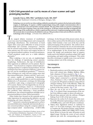
1. Randomlypositionacast ofthe existingear on aplat-
form with colored pins (Ballpin; Buffetti, Milan,
Italy) (diameter 2.5 mm) around it. (Fig. 1, A)
2. Use a laser scanner (Minolta VIVID 900; Minolta,
Osaka, Japan) connected to a personal computer
(Asus, Pentium 4 /2.8, 1 GB Ram, HD 80 GB)
to acquire the 3D spatial coordinates using software
(Polygon Editing Tool v1.03;.Minolta). Make the
first measurement after positioning the stone cast
in front of the laser scanner. (Fig. 1, B)
3. Place the cast of the ear in 8 random positions
(Fig. 2) to obtain 8 laser measurements of the sur-
face from different angles to detect all undercuts.
4. Record these patterns with the software (Polygon
Editing Tool v1.03) of the laser scanner.
5. Represent the surface by 8 clouds (the entire num-
ber of the 3D points representing a volume surface)
of 50,000 points, each with 3D point coordinates.
6. Adjust these digitalized surfaces as explained in
steps 7 to 14 of this technique, then merge them
to combine the 3D clouds of points, using software
(Inus Rapidform 2004 CAD v2004; INUS Techn,
Seoul, Korea) to locate the same 3D points in each
digital image. Overlap the center of each colored
spherical pin with the corresponding pin in the
a
Clinical Assistant Professor of Maxillofacial Prosthesis, Section of Oral
and Maxillofacial Rehabilitation, Department of Oral Science.
b
Dean and Professor of Prosthodontics, Section of Oral and
Maxillofacial Rehabilitation, Department of Oral Science.
DECEMBER 2004 THE JOURNAL OF PROSTHETIC DENTISTRY 591
2. other diverse angled image scans and integrate all
measurements (Fig. 3).
Data elaboration
7. Use the ‘‘Register 2 Shells’’ function for the recom-
bination and alignment of the pairs of scans through
3D translations.
8. Use the ‘‘Register Fine’’ function to permit the en-
tire surface to be recombined by using an automatic
algorithm.
9. Use the ‘‘Merge Mesh’’ function to blend the dif-
ferent surfaces into 1 virtual model and to construct
a surface with the 3D values of each corresponding
point of the different scans.
10. Use the ‘‘Clean Abnormal Face’’ function to elimi-
nate surface abnormalities of the previously elabo-
rated shell.
11. Use the ‘‘Smooth’’ function to smooth the surface
of the image.
12. Use the ‘‘Remesh’’ command to allow for the orga-
nization of the triangulated mesh of the points.
13. Use the ‘‘Decimate’’ function to reduce the magni-
tude of the computerized file.
14. Use the ‘‘Fill Holes’’ function to automatically or
manually eliminate surface gaps that remain after
data elaboration.
15. Develop an STL-integrated 3D digital file with the
software, using the ‘‘Export as STL file’’ function.
16. Copy and mirror the existing surface (Fig. 4) using
the ‘‘Divide/Mirror’’ tool to permit visualization of
the defective ear as it appeared before ablative sur-
gery.
CAD-CAM technology and rapid prototyping
procedure
17. Process the STL file using the computer system (Z
Printer 310; Z Corp, Burlington, Mass) to manu-
facture the definitive acrylic ear cast in a single step.
By using the Z Printer 310 machine, provide a layer
of sealant (Z Corp Sealant; Z Corp) with a layer of
resin powder (Z Corp Powder; Z Corp) and de-
velop the entire volume through layer-by-layer
manufacturing.
18. Allow 60 minutes for the acrylic resin to polymerize.
19. Extract the cast from the powder and then infiltrate
the surface of the manufactured ear with cyanoacry-
Fig. 1. A, Colored pins for repositioning diverse angled
images. B, Minolta Vivid 900 laser scanner.
Fig. 2. Eight random positions of laser scanner.
THE JOURNAL OF PROSTHETIC DENTISTRY CIOCCA AND SCOTTI
592 VOLUME 92 NUMBER 6
3. late (496; Loctite Italia, Brugherio, Italy) to further
harden the acrylic resin ear (Fig. 5).
Prosthesis production
20. Use a vinyl polysiloxane material (Zetalabor
Platinum; Zhermack, Badia Polesine, Italy) to
transform the acrylic resin cast into a wax ear.
21. Make a mold with the silicone, leaving an opening
in the mold all around the base of the prototyped
ear.
22. Split the vinyl polysiloxane mold during the re-
moval of the resin cast and recompose it using the
cyanoacrylate before pouring the mold with the
wax (Tenatex; Associated Dental Products,
Imadent, Turin, Italy).
23. Once the wax hardens, separate the 2 parts of the
mold and extract the wax cast from the silicone
mold.
24. Adapt the margins of the mirrored section to the
post surgical face asymmetries. The mirror projec-
tion of the corresponding surface will not initially
fit in the resection cavity (Fig. 6).
25. Perform conventional processing procedures as de-
scribed by Beumer et al14
to obtain the definitive
prosthesis (Fig. 7).
26. Use a spectrophotometer to determine the intrinsic
color of the ear (SpectroShade Office; MHT,
Verona, Italy)
27. Apply extrinsic colors (Extrinsic; Factor II, Lakeside,
Ariz), and use acetoxy silicone adhesive (A-564;
Factor II) to seal the coloration onto the silicone.
Fig. 3. Reproduction of overlapping process.
Fig. 4. Digitalized image is copied and mirrored.
THE JOURNAL OF PROSTHETIC DENTISTRYCIOCCA AND SCOTTI
DECEMBER 2004 593
4. DISCUSSION
Several research protocols have proposed technical
computer-assisted solutions, however, this article de-
scribes a simple, inexpensive, and repeatable method
of obtaining a definitive wax cast of a maxillofacial
prosthesis. Using a pin system around the ear cast
prior to duplication, 8 laser measurements of the sur-
face from new angles allow for the detection of all un-
dercuts. Each colored sphere at the top of the pin
permits the detection the center point from every an-
gle it is observed and subsequently the recombination
of the different angled images which overlap with the
corresponding colored pin center of the other diverse
image scans (Fig. 3). The software blends the differ-
ent surfaces of the ear into 1 virtual 3D model using
the sphere around the cast, whose perimeters and ce-
nters may be easily detected and overlapped with the
corresponding one in the other images of the different
scans. Other recent studies7,12
have proposed scan-
ning methods which used custom-made laser scanners
or expensive rapid prototyping devices. This tech-
nique requires only a conventional laser scanner and
a commercial 3D printer.
This technique is also faster and less expensive than
the work of an anaplastologist which is done by hand.
However, it should be noted that the authors had use
of equipment at the Architectural Department of the
Engineering Department at the University of Bologna,
Italy, free of charge. The equipment needed is similar
to that used for the rapid prototyping process in archi-
tectural modeling. If access to such a computerized sys-
tem is available, the only cost is the powder and the
sealant of the 3D printer. Using this equipment, the
procedure takes no more than 8 hours, the majority of
which is spent on data elaboration.
This technique, used for computer-generated facial
prosthesis construction, has several advantages. The la-
ser scanner and the rapid prototyping machine used for
reproducing a mirrored cast of an existing ear with this
technique are commonly available. Data acquisition
and elaboration is less time consuming and expensive
than with previously described methods or fabricating
the wax prosthesis manually. Surface data may be corrected
Fig. 5. A, Rapid prototyping in acrylic of undercuts. B, Frontal view of acrylic final result (on left).
Fig. 7. Definitive result.
Fig. 6. Initial trial of wax ear obtained through silicone
duplication on patient.
THE JOURNAL OF PROSTHETIC DENTISTRY CIOCCA AND SCOTTI
594 VOLUME 92 NUMBER 6
5. and adapted to more accurately reconstruct the prosthesis.
The definitive resin cast may be saved in a maxillofacial
prosthetic computerized library and reproduced when
the prosthesis requires repair or duplication.
A disadvantage of this clinical procedure is the lack of
detailed color information. The use of a spectrophotom-
eter is necessary to obtain precise color matching.15
If
clinicians do not have a specialized, cost-free laboratory
at their disposal, the price of the recommended technical
equipment may be a disadvantage.
Future developments might include a color map of
the definitive prosthesis by means of a spectrophotome-
ter-assisted color calibration of the surface. The integra-
tion of the 2 systems, color and volume, would be
required. Moreover, future developments may include
details of the undercuts and the adaptation of the acrylic
resin cast to the resection margins. In addition, the sys-
tem for the fabrication of a maxillofacial prosthesis might
be used as a presurgical template for the craniofacial
implant positioning diagnosis by means of a CT scan.
SUMMARY
This article describes a technique for making maxillo-
facial prostheses using CAD-CAM technology and
a rapid prototyping machine. A laser scanner was used
to develop an integrated 3D digital image of the existing
ear of a patient subjected to auricle ablative surgery. The
image was mirrored and used to manufacture the solid
ear cast by means of a rapid prototyping machine. This
procedure is time and cost effective if the technology is
available free of charge. Subsequently, the definitive
prosthesis was obtained through conventional pro-
cedures.
The authors thank Professor Roberto Mingucci and Mr. Giovanni
Bacci, technician, of the Department of Architecture and Engineer-
ing at the University of Bologna, for their attention to protocol
development and for use of the informatic instrumentation of the
SILAB laboratory.
The authors also thank ZCorp’s Italian distributor, Dr. Guanluca
Pieri, for technical assistance during the manufacturing protocol of
the resin rapid-prototyped models.
REFERENCES
1. Beumer J, Curtis TA, Marunick MT. Maxillofacial rehabilitation: prosthetic
and surgical consideration. St Louis: Medico Dental Media International;
1996. p. 18.
2. Hecker DM. Maxillofacial rehabilitation of a large facial defect resulting
from an arteriovenous malformation utilizing a two-piece prosthesis.
J Prosthet Dent 2003;89:109-13.
3. Girod S, Keeve E, Girod B. Advances in interactive craniofacial surgery
planning by 3D simulation and visualization. Int J Oral Maxillofac Surg
1995;24:120-5.
4. Coward TJ, Watson RM, Wilkinson IC. Fabrication of a wax ear by rapid-
process modeling using stereolithography. Int J Prosthodont 1999;12:
20-7.
5. Penkner K, Santler G, Mayer W, Pierer G, Lorenzoni M. Fabricating auric-
ular prostheses using three-dimensional soft tissue models. J Prosthet Dent
1999;82:482-4.
6. Runte C, Dirksen D, Delere` H, et al. Optical data acquisition for com-
puter-assisted design of facial prostheses. Int J Prosthodont 2002;15:
129-32.
7. Reitemeier B, Notni G, Heinze M, Schone C, Schmidt A, Fichtner D.
Optical modeling of extraoral defects. J Prosthet Dent 2004;91:80-4.
8. Nusinov NS, Gay WD. A method for obtaining the reverse image of an
ear. J Prosthet Dent 1980;44:68-71.
9. Mankovich NJ, Curtis DA, Kagawa T, Beumer J 3rd. Comparison of com-
puter-based fabrication of alloplastic cranial implants with conventional
techniques. J Prosthet Dent 1986;55:606-9.
10. Lemon JC, Okay DJ, Powers JM, Martin JW, Chambers MS. Facial mou-
lage: the effect of a retarder on compressive strength and working and set-
ting times of irreversible hydrocolloid impression material. J Prosthet Dent
2003;90:276-81.
11. Kubon TM, Anderson JD. An implant-retained auricular impression tech-
nique to minimize soft tissue distortion. J Prosthet Dent 2003;89:97-101.
12. Cheah CM, Chua CK, Tan KH, Teo CK. Integration of laser surface digitiz-
ing with CAD/CAM techniques for developing facial prosthesis. Part 1: de-
sign and fabrication of prosthesis replicas. Int J Prosthodont 2003;16:
435-41.
13. Cheah CM, Chua CK, Tan KH, Teo CK. Integration of laser surface digitiz-
ing with CAD/CAM techniques for developing facial prosthesis. Part 2: de-
velopment of molding techniques for casting prosthetic parts. Int J
Prosthodont 2003;16:543-8.
14. Beumer J, Curtis TA, Marunick MT. Maxillofacial rehabilitation: prosthetic
and surgical considerations. St Louis: Medico Dental Media International;
1996. p. 377-453.
15. Taylor TD. Clinical maxillofacial prosthetics. Chicago: Quintessence;
2000. p. 245-64.
0022-3913/$30.00
Copyright Ó 2004 by The Editorial Council of The Journal of Prosthetic
Dentistry
doi:10.1016/j.prosdent.2004.08.021
THE JOURNAL OF PROSTHETIC DENTISTRYCIOCCA AND SCOTTI
DECEMBER 2004 595