Global system for mobile
•Télécharger en tant que DOCX, PDF•
3 j'aime•927 vues

CEPT began developing the Global System for Mobile (GSM) network in 1982 with the objectives of pan-European roaming and compatibility with ISDN. The first commercial GSM system was implemented in Germany in 1992. GSM consists of mobile stations, base station subsystems, a network and switching subsystem, and an operation subsystem. It uses TDMA to allow multiple users to access the same radio frequency channel simultaneously. GSM has undergone 35 revisions to accommodate unexpected rapid growth in cellular services.

Recommandé
Contenu connexe
Tendances
Tendances (20)
Similaire à Global system for mobile
Similaire à Global system for mobile (20)
Dernier
Dernier (20)
Global system for mobile
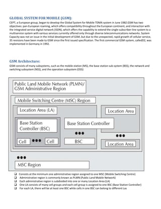
- 1. GLOBAL SYSTEM FOR MOBILE (GSM): CEPT, a European group, began to develop the Global System for Mobile TDMA system in June 1982.GSM has two objectives: pan-European roaming, which offers compatibility throughout the European continent, and interaction with the integrated service digital network (ISDN), which offers the capability to extend the single-subscriber-line system to a multiservice system with various services currently offered only through diverse telecommunications networks. System Capacity was not an issue in the initial development of GSM, but due to the unexpected, rapid growth of cellular service, 35 revisions have been made to GSM since the first issued specification. The first commercial GSM system, calledD2, was implemented in Germany in 1992. GSM Architecture: GSM consists of many subsystems, such as the mobile station (MS), the base station sub system (BSS), the network and switching subsystem (NSS), and the operation subsystem (OSS) Consists at the minimum one administrative region assigned to one MSC (Mobile Switching Centre) Administrative region is commonly known as PLMN (Public Land Mobile Network) Each administrative region is subdivided into one or many Location Area (LA) One LA consists of many cell groups and each cell group is assigned to one BSC (Base Station Controller) For each LA, there will be at least one BSC while cells in one BSC can belong to different Las
- 2. Cells are formed by the radio areas covered by a BTS (Base Transceiver Station) Several BTSs are controlled by one BSC Traffic from the MS (Mobile Station) is routed through MSC Calls originating from or terminating in a fixed network or other mobile networks is handled by the GMSC (Gateway MSC) It contains the following information: 1. Authentication information like International Mobile Subscriber Identity (IMSI) 2. Identification information like name, address, etc. of the subscriber 3. Identification information like Mobile Subscriber ISDN (MSISDN) etc. 4. Billing information like prepaid or postpaid 5. Operator selected denial of service to a subscriber 6. Handling of supplementary services like for CFU (Call Forwarding Unconditional), CFB (Call Forwarding Busy), CFNR (Call Forwarding Not Reachable) or CFNA (Call Forwarding Not Answered) 7. Storage of SMS Service Center (SC) number in case the mobile is not connectable so that whenever the mobile is connectable, a paging signal is sent to the SC 8. Provisioning information like whether long distance and international calls allowed or not 9. Provisioning information like whether roaming is enabled or not 10. Information related to auxiliary services like Voice mail, data, fax services, etc. 11. Information related to auxiliary services like CLI (Caller Line Identification), etc. 12. Information related to supplementary services for call routing. In GSM network, one can customize the personal profile to the extent that while the subscriber is roaming in a foreign PLMN, incoming calls can be barred. Also, outgoing international calls can be barred, etc.
- 3. 13. Some variable information like pointer to the VLR, location area of the subscriber, Power OFF status of the handset, etc. Entities in GSM The Mobile Station (MS) - This includes the Mobile Equipment (ME) and the Subscriber Identity Module (SIM). The Base Station Subsystem (BSS) - This includes the Base Transceiver Station (BTS) and the Base Station Controller (BSC). The Network and Switching Subsystem (NSS) - This includes Mobile Switching Center (MSC), Home Location Register (HLR), Visitor Location Register (VLR), Equipment Identity Register (EIR), and the Authentication Center (AUC). The Operation and Support Subsystem (OSS) - This includes the Operation and Maintenance Center (OMC). 1. The Mobile Station: The MS may be a stand-alone piece of equipment for certain services or support the connection of external terminals, such as the interface for a personal computer or fax. The MS includes mobile equipment (ME) and a subscriber identity module (SIM). ME does not need to be personally assigned to one subscriber. The SIM is a subscriber module which stores all the subscriber-related information. When a subscriber’s SIM is inserted into the ME of anMS, that MS belongs to the subscriber, and the call is delivered to that MS. The ME is not associated with a called number—it is linked to the SIM. In this case, any ME can be used by a subscriber when the SIM is inserted in the ME. 2. Base Station Subsystem: The BSS connects to the MS through a radio interface and also connects to the NSS. The BSS consists of a base transceiver station (BTS) located at the antenna site and a base station controller (BSC) that may control several BTSs. The BTS consists of radio transmission and reception equipment similar to the ME in an MS. A transcoder/rate adaption unit (TRAU) carries out encoding and speech decoding and rate adaptation for transmitting data. As a subpart of the BTS, the TRAU may be sited away from the BTS, usually at the MSC. In this case, the low transmission rate of speech code channels allows more compressed transmission between the BTS and the TRAU, which is sited at the MSC. 3. Network and Switching Subsystem:NSS in GSM uses an intelligent network (IN). The IN’s attributes will be described later. A signaling NSS includes the main switching functions of GSM. NSS manages the communication between GSM users and other telecommunications users. NSS management consists of: Mobile service switching center (MSC): Coordinates call set-up to and from GSM users. An MSC controls several BSCs. Interworking function (IWF): A gateway for MSC to interface with external networks for communication with users outside GSM, such as packet-switched public data network (PSPDN) or circuit-switched public data network (CSPDN).The role of the IWF depends on the type of user data and the network to which it interfaces. Home location register (HLR): Consists of a stand-alone computer without switching capabilities, a database which contains subscriber information, and information related to the subscriber’s current location, but not the actual location of the subscriber. A subdivision of HLR is the authentication center (AUC). The AUC manages the security data for subscriber authentication. Another sub-division of HLR is the equipment identity register (EIR) which stores the data of mobile equipment (ME) or ME-related data. Visitor location register (VLR): Links to one or more MSCs, temporarily storing subscription data currently served by its corresponding MSC, and holding more detailed data than the HLR. For example, the VLR holds more current subscriber location information than the location information at the HLR Gateway MSC (GMSC): In order to set up a requested call, the call is initially routed to a gateway MSC, which finds the correct HLR by knowing the directory number of the GSM subscriber. The GMSC has an interface with
- 4. the external network for gatewaying, and the network also operates the full Signaling System 7 (SS7) signaling between NSS machines. Signaling transfer point (STP): Is an aspect of the NSS function as a stand-alone node or in the same equipment as the MSC. STP optimizes the cost of the signaling transport among MSC/VLR, GMSC, and HLR 4. Operation Subsystem: There are three areas of OSS, (1) network operation and maintenance functions, (2) subscription management, including charging and billing, and (3) mobile equipment management. These tasks require interaction between some or all of the infrastructure equipment. OSS is implemented in any existing network. SMS Two types of SMS: SMMT (Short Message Mobile Terminated Point-to-Point) and SMMO (Short Message Mobile Originated Point-to-Point) SMMT is an incoming short message from the network and is terminated in the MS (phone or Mobile Station) SMMO is an outgoing message originated in the MS, and forwarded to the network for delivery For an outgoing message, the SMS is sent from the phone to SC via the VLR and the Inter Working MSC (IWMSC) For incoming message, the path is from SC to the MS via the HLR and the Gateway MSC (GMSC) Call routing inGSM: Digitizer and source coding: The user speech is digitized at 8 KHz sampling rate using Regular Pulse Excited–Linear Predictive Coder (RPE–LPC) with a Long Term Predictor loop where information from previous samples is used to predict the current sample. Each sample is then represented in signed 13-bit linear PCM value. This digitized data is passed to the coder with frames of 160 samples where encoder compresses these 160 samples into 260-bits GSM frames resulting in one second of speech compressed into 1625 bytes and achieving a rate of 13 Kbits/sec
- 5. Channel coding: This introduces redundancy into the data for error detection and possible error correction where the gross bit rate after channel coding is 22.8 kbps (or 456 bits every 20 ms). These 456 bits are divided into eight 57-bit blocks and the result is interleaved amongst eight successive time slot bursts for protection against burst transmission errors. Interleaving: This step rearranges a group of bits in a particular way to improve the performance of the error-correction mechanisms. The interleaving decreases the possibility of losing whole bursts during the transmission by dispersing the errors. Ciphering: This encrypts blocks of user data using a symmetric key shared by the mobile station and the BTS. Burst formatting: It adds some binary information to the ciphered block for use in synchronization and equalization of the received data. Modulation: The modulation technique chosen for the GSM system is the Gaussian Minimum Shift Keying (GMSK) where binary data is converted back into analog signal to fit the frequency and time requirements for the multiple access rules. This signal is then radiated as radio wave over the air Multipath and equalization:An equaliser is in charge of extracting the ‘right’ signal from the received signal while estimating the channel impulse response of the GSM system and then it constructs an inverse filter. The received signal is then passed through the inverse filter.
- 6. Synchronization: For successful operation of a mobile radio system, time and frequency synchronization are needed. Frequency synchronization is necessary so that the transmitter and receiver frequency match (in FDMA) while Time synchronization is necessary to identify the frame boundary and the bits within the frame (in TDMA). To avoid collisions of burst transmitted by MS with the adjacent timeslot such collisions, the Timing Advance technique is used where frame is advanced in time so that this offsets the delay due to greater distance. Using this technique and the triangulation of the intersection cell sites, the location of a mobile station can be determined from within the network. PLMN Interfaces Basic configuration of a GSM network contains a central HLR and a central VLR where HLR contains all security, provisioning and subscriber related information and VLR stores the location information and other transient data. MSC needs subscriber parameter for successful call set-up. Any data related to user call (connection, teardown etc.) are processed with SS7 protocol for signaling using ISUP (ISDN User Part) stack between network nodes. For mobile specific signaling, a protocol stack called MAP (Mobile Application Part) is used over the SS7 network which does all database transactions and handover/roaming transactions between the MSC. GSM Addresses and Identifiers: International Mobile Station Equipment Identity (IMEI): Every mobile equipment in this world has a unique identifier which is called IMEI. IMEI is allocated by the equipment manufacturer and registered by the network operator in the Equipment Identity Register (EIR). International Mobile Subscriber Identity (IMSI): When registered with a GSM operator, each subscriber is assigned a unique identifier called IMSI which is stored in the SIM card and secured by the operator. IMSI consists of several parts: 3 decimal digits of Mobile Country Code (MCC), 2 decimal digits of Mobile Network Code (MNC) and a maximum of 10 decimal digits of Mobile Subscriber Identification Number (MSIN) which is a unique number of the subscriber within the home network. Mobile Subscriber ISDN Number (MSISDN): The MSISDN number is the real telephone number as is known to the external world. MSISDN number is public information whereas IMSI is private to the operator. IMSI can be multiple such as when a subscriber opts for fax and data, he is assigned a total of three numbers: one for voice call, one for fax call and another for data call. MSISDN follows the international ISDN (Integrated Systems Data Network) numbering plan. ISDN has Country Code (CC) of 1 to 3 decimal digits, National Destination Code (NDC) of 2 to 3 decimal digits and Subscriber Number (SN) of maximum 10 decimal digits. Location Area Identity: Each LA in a PLMN has its own identifier called Location Area Identifier (LAI) which is structured hierarchically and unique. LAI consists of 3 digits of CC, 2 digits of Mobile Network Code and maximum of 5 digits of Location Area Code. Mobile Station Roaming Number (MSRN): When a subscriber is roaming in another network, a temporary ISDN number is assigned to the subscriber called MSRN. MSRN is assigned by the local VLR in charge of the mobile station and follows the structure of MSISDN. Temporary Mobile Subscriber Identity (TMSI): TMSI is a temporary identifier assigned by the serving VLR used in place of the IMSI for identification and addressing of the mobile station. Together with the current location area, a TMSI allows a subscriber to be identified uniquely.
- 7. Local Mobile Subscriber Identity (LMSI): LMSI is assigned by the VLR and stored in the HLR and is used as a searching key for faster database access within the VLR. Cell Identifier: Within a LA, every cell has a unique Cell Identifier (CI) and together with a LAI, a cell can be identified uniquely through Global Cell Identity (LAI & CI). MSCs and Location Registers (HLR & VLR) are addressed with ISDN numbers while they may use a Signaling Point Code (SPC) within a PLMN Network aspects in GSM Pic: Signaling protocol structure in GSM Layer 1 is the physical layer which uses the channel structures over the air interface. Layer 2 is the data link layer and across the Um interface, the data link layer is a modified version of the LAPD protocol used in ISDN or X.25, called LAPDm. Across the A interface, the Message Transfer Part layer 2 of Signaling System Number 7 is used. Layer 3 of the GSM signaling protocol is itself divided into three sub-layers: Radio Resources Management: It controls the set-up, maintenance and termination of radio and fixed channels, including handovers. Mobility Management: It manages the location updating and registration procedures as well as security and authentication. Connection Management: It handles general call control and manages Supplementary Services and the Short Message Service. Handover: The procedure of change of resources is called handover when the user is mobile while the call is in progress. There are four different types of handover in the GSM system, which involve transferring a call between: 1. Channels (time slots) in the same cell 2. Cells (Base Transceiver Stations) under the control of the same Base Station Controller (BSC)
- 8. 3. Cells under the control of different BSCs but belonging to the same Mobile Switching Center (MSC) 4. Cells under the control of different MSCs First two types of handover, called internal handovers, involve only one Base Station Controller (BSC). To save signaling bandwidth, they are managed by the BSC without involving the Mobile services Switching Center (MSC), except to notify it at the completion of the handover. Last two types of handover, called external handovers, are handled by the MSC. Mobility Management Mobility Management (MM) function handles the procedures that arise from the mobility of the subscriber and is in charge of all the aspects related to the mobility of the user, especially the roaming, the location management, and the security/authentication of the subscriber. First location update procedure is called the IMSI attach procedure where the MS indicates its IMSI to the network whereas when a mobile station is powered off, it performs an IMSI detach procedure in order to tell the network that it is no longer connected. A location update message is sent to the new MSC/VLR which records the location area information and then sends the location information to the subscriber’s HLR. If the mobile station is authenticated and authorized in the new MSC/VLR, the subscriber’s HLR cancels the registration of the mobile station with the old MSC/VLR. Location update is also performed periodically and if after the updating time period, the mobile station has not registered, it is then deregistered. When there is an incoming call for a subscriber, the mobile phone needs to be located and a channel needs to be allocated and the call connected. A powered-on mobile is informed of an incoming call by a paging message sent over the paging channel of the cells within the current location area while location updating procedures and subsequent call routing use MSC, HLR and VLR. If the subscriber is entitled to service, HLR sends a subset of the subscriber information needed for call control to the new MSC/VLR and sends a message to the old MSC/VLR to cancel the old registration. An incoming mobile terminating call is directed to the Gateway MSC (GMSC) function which, as a switch, interrogates the subscriber’s HLR to obtain routing information and thus contains a table linking MSISDNs to their corresponding HLRs. The routing information that is returned to the GMSC is the Mobile Station Roaming Number (MSRN). MSRNs are related to the geographical numbering plan and not visible to subscribers. Generally, GMSC queries the called subscriber’s HLR for an MSRN. HLR stores only the SS7 address of the subscriber’s current VLR while VLR temporarily allocates an MSRN from its pool for the call. MSRN is returned to the HLR and back to the GMSC, which can then route the call to the new MSC. At new MSC, IMSI corresponding to the MSRN is looked up and the mobile station is paged in its current location area. HLR is referred for incoming call whereas VLR is referred for outgoing call. GSM Frequency Allocation Normally, GSM uses 900 MHz band wherein 890-915 MHz is allocated for the uplink (mobile station to base station) and 935–960 MHz is allocated for the downlink (base station to mobile station). Each way the bandwidth for the GSM system is 25 MHz which provides 125 carriers uplink/downlink each having a bandwidth of 200 kHz. ARFCN (Absolute Radio Frequency Channel Numbers) denote a forward and reverse channel pair which is separated in frequency by 45 MHz. Practically, a guard band of 100 kHz is provided at the upper and lower end of the GSM 900 MHz spectrum and only 124 (duplex) channels are implemented. GSM uses a combination of Time Division Multiple Access (TDMA) and Frequency Division Multiple Access (FDMA) encoding.
- 9. One or more carrier frequencies are assigned to each base station and each of these carrier frequencies is then divided in time using a TDMA scheme where fundamental unit is called a burst period lasting approximately 0.577 ms. Eight burst periods are grouped into a TDMA frame of approximately 4.615 ms which forms the basic unit for the definition of logical channels. One physical channel is one burst period per TDMA frame while, normally, channels are defined by the number and position of their corresponding burst periods. PIC: Carrier frequencies and TDMA frames Authentication and Security Authentication involves two functional entities - the SIM card in the mobile phone and the Authentication Center (AUC). Following authentication by algorithm A3, a key is generated for encryption. An algorithm A8 is used to generate the key while a different algorithm called A5 is used for both ciphering and deciphering procedures for signaling, voice and data. So, SS7 signal, voice, data, and SMS within GSM networks are ciphered over the wireless radio interface. A3 Algorithm During authentication, MSC challenges the MS with a random number (RAND). SIM card uses this RAND received from the MSC and a secret key Kj stored within the SIM as input. Both the RAND and the Kj secret are 128 bits long. Using the A3 algorithm with RAND and Kj as input a 32-bit output called signature response (SRES) is generated in the MS and then sent back to MSC. Using the same set of algorithms, the AUC also generates a SRES. The SRES from MS and the SRES generated by the AUC are compared.
- 10. If they are the same, the MS is authenticated. The idea is that no keys will be transacted over the air. However, if the SRES values calculated independently by the SIM and the AUC are the same, then Kj has to be same and if Kj is same, SIM card is genuine. A8 Algorithm A8 algorithm is the key generation algorithm. A8 generates a session key, Kc, from the random challenge RAND (received from the MSC) and from the secret key Kj. Keys are generated at both the MS and the network end. The session key, Kc, is used for ciphering till the MSC decides to authenticate the MS once again. A5 Algorithm
- 11. A5 is the stream cipher algorithm used to encrypt over-the-air transmissions. The stream cipher is initialized all over again for every frame sent with the session key, Kc, and the number of the frame being encrypted or decrypted. Same Kc is used throughout the call but the 22-bit frame number changes during the call, thus, generating a unique key stream for every frame.