Interactive Powerpoint_How to Master effective communication
Final report- stirling
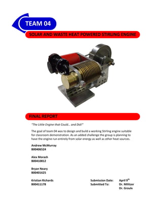
1. TEAM 04
SOLAR AND WASTE HEAT POWERED STIRLING ENGINE
FINAL REPORT
“The Little Engine that Could… and Did!”
The goal of team 04 was to design and build a working Stirling engine suitable
for classroom demonstration. As an added challenge the group is planning to
have the engine run entirely from solar energy as well as other heat sources.
Andrew McMurray
B00406524
Alex Morash
B00410812
Bryan Neary
B00401625
Kristian Richards Submission Date: April 9th
B00411178 Submitted To: Dr. Militzer
Dr. Groulx
2. TABLE OF CONTENTS
LIST OF ILLUSTRATIONS ............................................................................................................................... iv
.
LIST OF TABLES .............................................................................................................................................. v
ABSTRACT ..................................................................................................................................................... vi
1. INTRODUCTION ..................................................................................................................................... 1
2. BACKGROUND ....................................................................................................................................... 2
2.1. Ideal Stirling Engine Cycle ............................................................................................................. 2
2.2. Real Stirling Engine Cycle .............................................................................................................. 3
3. DESIGN REQUIREMENTS ....................................................................................................................... 6
4. DESIGN SELECTION ............................................................................................................................... 7
.
4.1. Rotary Stirling Engine .................................................................................................................... 8
4.2. Gamma Stirling Engine .................................................................................................................. 8
4.3. Alpha Stirling Engine ‐ 90° Arrangement ...................................................................................... 9
5. COMPONENT DESIGN, FABRICATION AND BUILD PROCESS ............................................................... 10
5.1. Frame .......................................................................................................................................... 10
5.2. Cylinders and Cylinder Heads ..................................................................................................... 11
5.3. Pistons ......................................................................................................................................... 12
5.4. Cranks ......................................................................................................................................... 12
.
5.5. Flywheel and Collars ................................................................................................................... 13
5.6. Piston Rods and Brass Connection Fittings ................................................................................. 14
5.7. Fresnel Spot Lens ........................................................................................................................ 14
6. DESIGN ANALYSIS AND REVISED CALCULATIONS ............................................................................... 16
6.1. Schmidt Analysis of Ideal Isothermal Model .............................................................................. 16
.
6.2. Fin Heat Transfer ......................................................................................................................... 18
7. INITIAL TESTING .................................................................................................................................. 19
7.1. Testing Observations................................................................................................................... 19
7.2. Design Solutions .......................................................................................................................... 20
8. DESIGN REFINEMENTS & PERFORMANCE IMPROVEMENTS .............................................................. 21
8.1. Design Refinements .................................................................................................................... 21
8.1.1. Frame Heat Dissipation ....................................................................................................... 21
8.1.2. Compression Reduction ...................................................................................................... 22
8.1.3. Transfer Tube ...................................................................................................................... 23
8.2. PERFORMANCE IMPROVEMENTS ............................................................................................... 24
ii
3. 8.2.1. Internal Fins ........................................................................................................................ 24
8.2.2. Regenerator ........................................................................................................................ 25
9. Testing and Troubleshooting .............................................................................................................. 27
9.1. Fresnel Lens Testing .................................................................................................................... 27
9.1.1. Test #1 ‐ General Testing Results ‐ January 23rd (2 pm) ...................................................... 27
9.1.2. Test #2‐ Temperature Measurements ‐ April 1st (12:40 to 1:10 pm) ................................. 28
.
9.1.3. Test #3 ‐ Solar Energy Input to Gamma ‘Windmill’ Stirling Engine ‐ April 1st ..................... 30
9.2. Iterative Testing and Troubleshooting Procedure ...................................................................... 30
9.3. Temperature Data Acquisition .................................................................................................... 33
9.3.1. Thermocouples ................................................................................................................... 33
9.3.2. Benchtop Digital Display ..................................................................................................... 34
9.3.3. Thermocouple arrangement ............................................................................................... 35
9.4. Stirling Engine Optimization........................................................................................................ 35
9.4.1. Test #1 ‐ March 30th, 2009 .................................................................................................. 36
9.4.2. Test #2 ‐ April 1st, 2009 ....................................................................................................... 37
9.4.3. Test #3 ‐ Run A ‐ April 4th, 2009 .......................................................................................... 39
9.4.4. Test #3 ‐ Run B ‐ April 4th, 2009 ........................................................................................... 42
9.4.5. Test #3 ‐ Run C ‐ April 4th, 2009 ........................................................................................... 43
9.5. Repeatability and Comparison to Theory ................................................................................... 44
10. BUDGET ............................................................................................................................................... 45
11. CONCLUSION ....................................................................................................................................... 46
11.1. Design Requirements Fulfillment ............................................................................................ 46
11.2. Optimal System Operating Condition ..................................................................................... 47
12. REFERENCES ........................................................................................................................................ 48
APPENDIX A – Gantt Chart
APPENDIX B – Ideal Isothermal Analysis
APPENDIX C – Heat Transfer Calculations
APPENDIX D – Engineering Drawings
iii
7. 1. INTR
RODUCTI
ION
In the recent ‘green‐en
nergy’ movem ment the Stirling cycle has received renewed interesst in the area of
solar enerrgy generatio
on, and it is th of team 04 to help raise aw
he intention o wareness and promote
renewable energies by y demonstrating the poten ntial of the Sti
irling engine.
Stirling en
ngines are kno own for havinng a high therrmodynamic efficiency. Id deally, a Stirlin
ng cycle enginne
can be de esigned to app proximate thee theoretical Carnot cycle engine. For e example, Stirrling Energy
Systems, Inc (SES), a co ompany based in California, USA specia alizing in solar
r energy gene eration equipment
is currently recognized d for holding t
the world reccord for solar‐‐to‐grid conve ersion efficienncy of 31.25% %
TM
T 1
with theirr SunCatcher solar powe ered Stirling e
engine and mi irrored dish c collector. See Figure 1 forr a
TM
picture off a proposed a array of SunC
Catcher unit ts. SES has proposed to bu uild 70,000 of these units in
the Californian Mojave e Desert and IImperial Valle
ey that will yield a combined generating g capacity of
1,750 MW W of electricity. Team 04 a
accredits thesse SES project ts as well as oother projects s of similar
aspirationns for inspiring the team too design and build a working Stirling en ngine to fulfill the requirem ments
of Dalhou usie Design Prroject 2008/009.
Figure 1 ‐ S
Solar Energy Pro
oject Proposal o ted in California Mojave Desert using SunCatch TM Technolog
of Solar Array sit her gies
2
from SES SStirling Energy Systems
The reporrt will outline a background of the ideal Stirling cyclee, summarize the design seelection process,
present th
he final design and individual compone ents, discuss t
the calculations and technical engineering
decisions made to refin ne the final design, presen nements and testing proce
nt design refin edures. The t
team
budget will also be preesented as we ell as a detaile
ed conclusionn outlining the
e design requ
uirements
establishe
ed in first sem
mester. The fiinal engineering drawings are attached d in the Appen
ndix D.
1 th
Stirling Energy Systems, SES. (2008a). New Wo
orld Record for Sola
ar‐to‐Grid Convers
sion Efficiency. Ac
ccessed on Septem
mber 20 , 2008 fro
om
http://www.s
stirlingenergy.com
m/downloads/12‐F
February‐2008‐SES
S‐Stirling‐Energy‐and‐Sandia‐National‐Laboratories‐se
et‐New‐World‐Rec
cord.pdf
2
Stirling Ene
ergy Systems, SEES. (2008b). Sola d on November 15th, 2008 from
ar Two. Accessed
http://www w.stirlingenergy.c
com/projects/de efault.asp
1
10. Figure 3 ‐ Real Stirling Cycle P‐v Diagram Approximation4
……………………………………………………………………………………… (1)
TH = Temperature of high thermal sink
TL = Temperature of low thermal sink
TR = Mass averaged gas temperature of regenerator leaving during heating
The Carnot efficiency is denoted by Equation 2 and the real cycle efficiency with regenerator is denoted
by Equation 3. Though regeneration is not required for a Stirling cycle, its inclusion can help improve
the efficiency if applied properly. Note how the regenerator efficiency does not tend to zero as the
regenerator effectiveness tends to zero.
1 ……………………………………….………….………….……………… (2)
⁄ ⁄ ⁄ ⁄
……………………………………… (3)
………………………………………………………………………... (4)
4
Power from the Sun. (2008b). Power Cycles for Electricity Generation. Accessed on October 12th, 2008 from
http://www.powerfromthesun.net/chapter12 /Chapter12new.htm#12.3.1%20%20%20%20%20Stirling%20Engines
4
12. 3. DESIGN REQUIREMENTS
The following design requirements of Table 2 summarize the scope of the project, the final goals, and
objectives team 04 intended to achieve.
Table 2 : Design Requirements
Design & Operational Elements
• Must be able to operate using a solar heat source.
• Must be able to operate using a compact heat source that is safe for indoor use.
• Must be able to operate unassisted after starting for a minimum of 5 minutes (except for a
controlling heat source).
• Must be built to a standard which delivers a minimum service life expectancy of 5 years, if
properly maintained.
Size, Weight and Complexity
• Total engine size and weight to be such that safe and easy transportation is possible by 1
person.
• Must be mounted on a compact support structure for stability and safety.
• Will be designed for ease of maintenance and assembly.
Aesthetics & Safety
• High temperature regions must be clearly indicated.
• Engine cylinder must be equipped with a removable fitting for piston inspection and pressure
release.
Documentation
• Supporting documentation and user instructions to be provided for later usage within the
Mechanical Engineering department of Dalhousie University.
Cost & Materials
• Pending the usage of machining time and salvaged components, the prototype is estimated to
cost less than $3500.
• Construction materials for the support frame and engine will consist mainly of steel or
aluminum, depending on cost, availability, and component purpose.
• Precision components such as pistons, piston rings, and bearings may be purchased off the shelf
or salvaged.
6
15. Figure 5 ‐ G
Gamma Stirling E
Engine
4.3. Alp
pha Stirling
g Engine ‐ 90° Arrang
gement
The 90° arrangement o of the Alpha SStirling Engine
e shown in Figure 6 featur
res two sealed d pistons with
h a
transfer tube and optio onal regeneraator between n the two cylin
nders. Whenn compared to o the rotary a
and
gamma co oncepts in thee selection m
matrix, the alpha arrangement is the mo ost efficient and produces the
most powwer. However r, due to the 9
90° orientatioon this concept has the po
otential to cre
eate more fricction.
Alignment of the shaft ts would be crrucial and anyy error would
d add to the s
system friction: ultimately
deciding wwhether or no ot the design succeeds.
Figure 6 ‐ Alpha Stir
rling Engine – 90
0° Arrangement
a) Expanssion ‐ Most of f the gas is in the hot cylinder and begin ns to expand driving both pistons inward.
Work i is output duriing the onset t of this proceess.
b) Transfeer ‐ Cold pisto
on is forced ddownward allo owing the heated gas to b be transfer to the cold cylin
nder.
c) Contraction ‐ Expan nded gas is in the cold cylin nder and cont tracts drawing both pistonns outward.
d) Transfeer ‐ The contrracted gas is s still located in
n the cold cylinder. Work is input into t
the system byy the
inertia
al energy of thhe flywheel w which carries t the crank throough 90°, transferring the gas back to tthe
hot cylinder, and co ompleting the e cycle.
9
16. 5. COMPONENT DESIGN, FABRICATION AND BUILD PROCESS
Following the design selection process the Inline Alpha Stirling Engine Arrangement shown in Figure 7
was chosen for the final design. This design excelled in the categories of power output, thermal
isolation, temperature differential and visual aesthetics.
Figure 7 ‐ Final Concept to Build Comparison
The design of our engine was based on ease of assembly and disassembly. Because of this, all
components are fastened together using either nuts and bolts or cap head machine screws. This was
beneficial for our team as it allowed for quick engine component modifications, such as size of stroke
length and piston rod length. The entire fabrication process took approximately one month. This was
due to the large number of parts and high level of precision required. The following sub‐sections will
outline the design methods of various components as well as discuss any modifications made to the
initial designs.
5.1. Frame
As depicted in Figure 8, the frame will be used to support the piston cylinders and flywheel rotating
assembly. The frame was constructed of ½” 6061 Aluminum Plate because it is light weight, durable and
easy to machine. The majority of the frame manufacturing was completed using a milling machine, with
the exception of parts that require a precision circular hole (i.e. flywheel supports and cylinder clamps).
The bearing seats in the supports for the flywheel were slightly changed during the fabrication process.
For a cleaner look, instead of having the bearing flush with the outside edge of the frame, the bearing
was pushed further into the stand and an internal retaining ring was used to hold it in place (Figure 8).
10
17. Figure 8 ‐ Assembled Frame and New Bearing Seat
5.2. Cylinders and Cylinder Heads
To maximize the heat transfer between the cold cylinder and the surrounding water bath the team
designed a simple array of annular fins to increase the external surface area of the cylinder. Heat
transfer calculations for steel and brass, available in Appendix C, show an approximate 320‐400%
increase in heat transfer with the addition of a fin 15mm in length. Based on these calculations the
team selected brass as the cold cylinder material as it enabled a larger heat transfer when compared to
steel. Other benefits of choosing brass over steel are that it will not rust in the ice bath and it has
improved dry frictional characteristics with steel (i.e. brass is a self lubricating metal).
The team chose a large number of fins with a spacing 2.5 times the thickness to ensure maximum
surface area. Because the system involves free convection it was important to choose large fin spacing.
By increasing the water volume between the fins the result is effectively an increase in the engine
efficiency. A larger volume of water between fins will take longer to heat up, thus maintaining a higher
temperature differential for an extended period of time.
The original cylinder design was a one piece cylinder and cylinder head. After some brainstorming and
discussions with our technician, our team decided it was best to construct the cylinder and cylinder head
in two pieces. This would allow for a more precise finish on the inside bore of the cylinders as well as
allow for easy assembly and troubleshooting if required. The manufacturing process was carried out
using a lathe. The finalized cylinders can be seen in Figure 9.
11
18. Figure 9 ‐ Hot and Cold Cylinders and Cylinder Heads
5.3. Pistons
To help reduce friction and increase durability, grooved pistons are used in our system. The grooves
around the piston serve as a pressure seal when the piston and cylinder are machined to low tolerances.
The piston was originally going to be constructed of cold rolled steel to ensure consistency in thermal
expansion for the hot cylinder assembly. However, our technician supplied us with a similar material
that was easier to machine and finish. This was considered to be important due to the high tolerances
between the piston and cylinder walls. The better the surface finish the lower the friction generated.
The brass‐on‐steel interaction between the cold cylinder and piston will not pose an issue for thermal
expansion due to the low temperature gradient across the cold cylinder assembly as designed. The
interaction of brass and steel has low sliding frictional properties. Figure 10 displays the manufacturing
process of one of the pistons on the lathe as well as the finished product.
Figure 10 ‐ Piston Manufacturing and Final Product
5.4. Cranks
The design of the cranks had to incorporate two things, stroke length and the generation of a force
couple. The stroke length of our system is twice the distance from the center of rotation of the crank to
12
20. Figure 12 ‐ Stirling Cycle Flywheel Dependance
5.6. Piston Rods and Brass Connection Fittings
The fittings used to connect the piston rods to the pistons and cranks were made of brass due to its low
sliding frictional properties. During the manufacturing process a slight modification was made to one of
the brass fittings. The length of the piece closest to the piston was increased from 0.875” to 1.125” to
allow for more threads for the machine screw holding the piston in place. As a result the original piston
rod length was shortened by 0.250”. Team 04 made sure to make brass fitting design simple to inter‐
change piston rod length as it might be necessary during the testing phase of the project. The piston rod
and brass fitting setup can be seen in Figure 13.
Figure 13 ‐ Brass Fittings and Connecting Rods
5.7. Fresnel Spot Lens
For the solar aspect of our design project our team selected a Fresnel Spot Lens. A spot lens was chosen
for its concentrated beam shape and adjustability in focusing the incident solar radiation onto the hot
cylinder head. The Lens was purchased online and measures 27” x 36”. Our team constructed a frame
for the lens that allows for vertical adjustments as well as 360° rotation about the horizontal axis. This
14
26. Heat Damage
Figure 19 ‐ Heat Damage to Temporary Transfer Tube
7.2. Design Solutions
Initial testing provided useful information regarding engine performance and highlighted undesirable
conditions. Solutions to these issues were addressed during the design refinement process and include
reducing stroke length to decrease compression, insulating hot cylinder from the frame, replacing the
rubber transfer tube with a metal pipe, and promoting heat transfer to the working gas.
20
28. Figure 21 ‐ Thermal Image
8.1.2. Compression Reduction
It was evident from the initial test that the cylinder compression was too high for the scale of our
application. The pressures achieved in the cylinders were enough to cause significant vibration and
bending of the frame itself. High compression, however, is the main characteristic of the Alpha type
Stirling engine due to there being two sealed pistons and cylinders. Suitable compression ratios for
these types of engines are not well documented therefore an iterative design refinement was required
when trying to achieve a compression ratio that provided a significant performance increase.
To reduce the compression, two options were available. One was to decrease the stroke length which
would reduce the volume of air being compressed; the second was to reduce the connecting rod length
which would increase the minimum volume of the system there by decreasing the amount of
compression.
The stroke length was first reduced by ¾” by drilling new holes in the cranks. This significantly reduced
the compression and provided the first noteworthy performance gains. After testing this stroke length
with various sizes of connecting rods, the stroke was again reduced by 5/8”, see Figure 22. After
machining several new sizes of connecting rods, it was possible to significantly decrease the
compression of the system. The motor exhibited “signs of life” and would attempt to maintain itself in
operation.
22
29. Figure 22 ‐ Stroke Length Reduction
8.1.3. Transfer Tube
The original transfer tube, which was only selected for initial testing, had a maximum temperature
rating that was much less than the application required. Heat quickly conducted through the brass
fitting on the cylinder head, elevating the temperature of the hose beyond its melting point. Sufficient
testing was unable to be performed until a suitable replacement transfer connection was found.
Several attempts were made to build a transfer tube using ½”copper pipe; however, soldering the joints
was not an option as most solder has a melting temperature of around 190°C which is below the
operating temperature of the hot cylinder. The brass fitting on the cylinder head had the potential to
melt the solder. An alternative to soldering the joints was the use of JB weld. This provided initial
success however sufficient temperatures caused the JB weld to crack, reducing the integrity of the
transfer tube, see Figure 23. Finally the use of threaded steel fittings provided an adequate solution that
withstood repeated tests without diminished results, see Figure 24.
Figure 23 ‐ Heat Damaged Transfer Tube
23
30. Figure 24 ‐ Steel Transfer Tube
8.2. PERFORMANCE IMPROVEMENTS
Following several iterations of design refinements, many of the initial complications were overcome. In
an effort to improve the performance and efficiency of the engine, several engineering improvements
were made. Due to the extensive amount of time dedicated to design and the high quality of machining,
the engine had a high mechanical efficiency. Frictional losses were not a major factor limiting
performance; however, it was evident that improvements were required to increase the thermal
efficiency of the system.
8.2.1. Internal Fins
Early in the design process initial brainstorming began on an internal fin array that would increase heat
transfer to and from the working gas. This concept was not finalized before fabrication of the engine had
commenced and the idea was put on hold. After the initial testing provided insight into the thermal
efficiency of the engine, it was decided that internal fins might provide increased engine performance.
The internal fin array was to be seated against the cylinder head (both hot and cold) and in the direct
path of the gas flow to maximize heat transfer. The fins of an aluminum vehicle radiator provided an
ideal solution with relatively minimal fabrication required. A used radiator was salvaged from an auto
shop and a portion of the fin structure was removed. A circular pattern equal to the internal diameter of
the cylinders was then applied to the section of radiator where it was then cut with a band saw and
sanded smooth, see Figure 25. Aluminum sleeves were machined to encase the circular fins and to
protect the cylinder walls from scratching. In addition to providing protection, the aluminum sleeves
ensure an intimate contact with the cylinder walls for the efficient heat transfer. Figure 26 shows the
completed fins situated in the cylinder. The internal fins proved effective at assisting heat transfer and
provided a notable performance increase.
24
31.
Figure 25 ‐ Internal Fins Fabrication Process
Figure 26 ‐ Internal Fin Placement
8.2.2. Regenerator
In an effort to further increase the thermal efficiency of the engine the use of a regenerator was
selected. The initial engine design called for the use of a regenerator, however, our limited
understanding of regenerator design and the difficulties we had already incurred due to troublesome
transfer tubes, made us reluctant to begin further modifications.
The effect of including a regenerator in the transfer tube had already been examined during the design
selection process and operates much like an economizer situated in the gas flow between the hot and
cold cylinders. The regenerator design consisted of a section of ¾”steel pipe with flanges welded on
each end, see Figure 27. The flanged pipe was fitted between the cylinders and replaced the existing
transfer tube, see Figure 28. Steel wool was inserted in the pipe to provide a dense thermal mass to
exchange heat with the gas flow between cylinders. The large surface area of the steel wool provided
25
34. Figure 30 depicts some of the various objects used to demonstrate the concentrating power of the
Fresnel lens. The first object is of an aluminum can that was held under the focal point for
approximately 10 seconds. Aluminum has a melting temperature of 660°C. Even though aluminum
has a high thermal conductivity and reflective surface the lens was still able to concentrate enough
energy fast enough to melt the aluminum. The amount of heating could be increased by insulating
the object from the environment and by painting the surface a dull black to minimize reflectivity.
The lens was also capable of creating molten asphalt. It was also demonstrated that the lens could
set fire to wood instantaneously.
Figure 30 ‐ Various Objects Held under the Fresnel Lens
9.1.2. Test #2‐ Temperature Measurements ‐ April 1st (12:40 to 1:10 pm)
The intent of this test was to determine the rate of heat absorption of a cylindrical steel object of
dimensions 3”D x 2‐1/8”L. The surface of the object was painted black and the sides and base were
insulated. A digital picture of the cylindrical steel object is shown in Figure 31. The ambient
temperature was 5°C on a clear, sunny day. The temperature was read at a depth of three quarters the
length using an infrared thermometer and recorded every 30 seconds for a total of 30 minutes. The
results are displayed in Figure 32 below. The temperature increases over time in an exponential
relationship as expected from theory (as the surface temperature increases the losses due to convection
and radiation increase so a leveling off occurs). Temperatures just above 310°C were achieved at the 30
minute mark.
The test was repeated with the propylene torch which is the heat source used during testing. The idea
here is to compare the relative heat transfer rates of the torch and lens. Figure 32 shows that it took
the torch half the time to reach temperatures above 310°C, so a very crude approximation suggests that
the torch has double the heating potential in comparison to the lens. Note that the performance of the
lens depends on the time of year, weather, time, and ambient air conditions, as well as other numerous
factors so it is possible to improve on this. It is very important to consider the testing results from
Section 9.4.5 which required the team to apply the torch only 40 to 50% of the operating time to sustain
peak RPM above 300. From these results, it is not difficult to say that it is very possible for the engine to
operate with the Fresnel lens alone under the right conditions.
28
35. Figure 31 ‐ Cylindrical Steel Object
Test #4 ‐ Fresnel Lens Testing
350
300
250
Temperature (°C)
200
150
100
50
0
0 5 10 15 20 25 30
Time (min)
Fresnel Lens Heat Source Propylene Torch Heat Source
Figure 32 ‐ Temperature Increase of Steel Stock vs. Time
By using the temperature data of heating the steel specimen over the 30 minutes a rough
estimate of the average net solar heating was calculated as 147 W. Considering an ideal solar
input of 314 W, the overall solar collection efficiency is about 47% depending on ambient
conditions. Since the heating rates of the torch are about double that of the Fresnel lens, a
conservative estimate for the amount of net heat input from the torch would be about 300 W.
These power rates are not absolute, but resemble the difference between input and losses and
would equal to zero once the temperature reaches steady state.
29