This document provides information for incorporating an embedded cellular antennas into wireless products in this case a Round Solutions antenna Specifications, design recommendations, board layout, packaging and manufacturing recommendations are included.
1. Embedded Antenna Application Note George Negreanu
Part I, 09-12-2010 www.linkedin.com/in/gsmgps
GSM GPRS UMTS
Embedded Antenna Application Note (Part I)
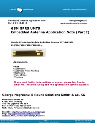
Standard Penta-Band Cellular Embedded Antenna ANT-GXE9506
850/900/1800/1900/2100 MHz
Applications:
●
M2M
●
Automotive
●
Automatic Meter Reading
●
Healthcare
●
Point of Sale
●
Tracking
If you need further informations or support please feel free to
email me. Antenna tuning and PCB optimization service available.
George Negreanu @ Round Solutions GmbH & Co. KG
Hans-Boeckler-Str. 16
63263 Neu-Isenburg
Tel: +49 (0)6102 799 28 0
Fax: +49 (0)6102 799 28 199
Web: http://www.roundsolutions.com
LinkedIn: http://www.linkedin.com/in/gsmgps
Blog: http://gsmantenna.wordpress.com/
Tweeter: http://twitter.com/George_Negreanu
Tel +49 6102 799 280 Page 1 Fax +49 6102 799 28 199
georgen@roundsolutions.com Round Solutions GmbH & Co KG www.roundsolutions.com
2. GSM GPRS UMTS Embedded Antenna Application Note George Negreanu
Part I, 09-12-2010 www.linkedin.com/in/gsmgps
Table of Contents
1 PURPOSE
3
2 OVERVIEW 3
3 DESIGN GUIDELINES 6
3.1 Introduction 6
3.2 Antenna Pad Layout 6
3.3 PCB Land Pattern 6
3.4 Antenna Location 7
3.5 Antenna Tuning Guidelines 12
3.6 Varying The Board Size 15
4 ANTENNA COMPONENTS 19
5 MATERIAL SPECIFICATIONS 20
6 PRODUCT TUNING GUIDE 20
7 MANUFACTURING AND ASSEMBLY GUIDELINES 22
8 APPENDIX 1 Summary of ANT- GXE9506 24
Tel +49 6102 799 128 Page 2 Fax +49 6102 799 28 199
georgen@roundsolutions.com Round Solutions GmbH & Co KG www.roundsolutions.com
3. GSM GPRS UMTS Embedded Antenna Application Note George Negreanu
Part I, 09-12-2010 www.linkedin.com/in/gsmgps
1. Purpose
This document provides information for incorporating an embedded cellular antennas
into wireless products in this case a Round Solutions antenna ANT-GXE9506. Specif cations, design recommendations,
i
board layout, packaging and manufacturing recommendations are included.
This document is divided into two parts: a main section and appendices. The main section addresses
points and issues common to all products. The appendices provide product-specif c information.
i
2. Overview
The ANT-GXE9506 Standard Penta-Band antenna, listed below, represents a new category of internal IMD an-
tennas.Round Solutions antennas utilize proprietary and patented Isolated Magnetic Dipole (IMD) technol-
ogy to meet the needs of device designers for higher performance; providing greater than 50% average
eff ciency across all f ve bands. Standard, off-the-shelf, antennas lower total costs, enable quicker time-
i i
to-market and work with a variety of designs.
Product Selector Guide
Antenna PN Application Type Typical Deliverable Size
ANT-GXE9506 Cellular Partial Ground SMT mountable antenna assembly
Flexible antenna placement 35.0 x 9.0 x 3.2 mm
850, 900 MHz
1800, 1900 MHz
2100 MHz
STK-GXE9506 Cellular Demo Board Antenna Assembly on PCB board
50 x 110 mm
850, 900 MHz
1800, 1900 MHz
2100 MHz
Additional antennas are under development, please see Round Solutions’ Website, or ask the Round Solutions'
Team about additional Products to meet your needs.
Tel +49 6102 799 128 Page 3 Fax +49 6102 799 28 199
georgen@roundsolutions.com Round Solutions GmbH & Co KG www.roundsolutions.com
4. GSM GPRS UMTS Embedded Antenna Application Note George Negreanu
Part I, 09-12-2010 www.linkedin.com/in/gsmgps
IMD Technology Advantages
Real-World Performance and Implementation
Round Solution continues to set the standard for antenna performance with its award-winning IMD technol-
ogy, which uses patented design conf gurations to conf ne the current f ow to the antenna element rather
i i l
than exciting the main circuit board. Other antennas may contain simple PiFA or monopole designs that
interact with their surroundings, complicating layout or changing performance with user position. Round-
Solutions’ antennas utilize patented IMD technology to deliver a unique size and performance combination.
Feature Advantage Benefits
High performance High eff ciency
i Meet and exceed design performance
specs. Lower design risks. Enhance end-
user satisfaction. Potential for additional
device sales.
High isolation Less interaction with surrounding compo-
nents. Smallest effective antenna size
when component keep-out areas are in-
cluded. Resists de-tuning due to orienta-
tion on circuit board. Lowers design risk
and time-to-market. One antenna part
number can serve multiple designs. Sim-
plif es design and ordering.
i
High selectivity Eliminates need for additional band-pass
i
f lters and other circuitry. Saves cost and
space.
Superior RF Field Virtually eliminates detuning due Better performance. Higher end-user sat-
Containment to device handling during use. isfaction. Potential for higher sales.
Tel +49 6102 799 128 Page 4 Fax +49 6102 799 28 199
georgen@roundsolutions.com Round Solutions GmbH & Co KG www.roundsolutions.com
5. GSM GPRS UMTS Embedded Antenna Application Note George Negreanu
Part I, 09-12-2010 www.linkedin.com/in/gsmgps
ANT-GXE9506 Penta-Band Cellular Antenna Features and Benefits Summary
Features Benefits
Cellular Eliminates external antennas
High Performance Embedded Solution Greater than 50% average eff ciency across all bands
i
Extensive design collateral and apps support Speeds development time
Standard “Off-the-Shelf” Product Speeds development time and reduces costs since
reduces NRE and custom development time
Small Form Factor & Ground Clearance Re- Can be used in a variety of custom form factors and
quirements applications
Cost Effective & Rugged Design SMT, Pick and Place, enable lower manufacturing
costs
Tel +49 6102 799 128 Page 5 Fax +49 6102 799 28 199
georgen@roundsolutions.com Round Solutions GmbH & Co KG www.roundsolutions.com
6. GSM GPRS UMTS Embedded Antenna Application Note George Negreanu
Part I, 09-12-2010 www.linkedin.com/in/gsmgps
3. Design Guidelines
3.1 Introduction
The ANT-GXE9506 Penta-Band Embedded Cellular Antenna can be designed into many wireless product
types. The following sections explain Round Solutions' recommended layouts to help the designer integrate
the antennas into a product with optimum performance.
3.2 Antenna Pad Layout
Figure 1 below shows the ANT-GXE9506 Cellular Penta-Band Antenna pad layout (bottom view) .
9mm
Antenna ground pad Antenna feed pad Pads for mechanical support
35mm
Figure 1
Maximum Dimensions: 35.0 x 9.0 x 3.2 mm
RF Mounting: RF Feed and Ground pads are SMT attached to the main PCB
Mechanical Mounting: Antenna Assembly is SMT attached to the main PCB
3.3 PCB Land Pattern
The PCB land pattern places the antenna matching circuit outside the antenna footprint for ease of re-
work.
Figure 2 below shows the PCB Land Pattern layout (top view) when the Matching Circuit is located out-
side the antenna footprint.
Antenna ground pad Antenna feed pad
10mm
Pads for mechanical support
50mm
Figure 2
Tel +49 6102 799 128 Page 6 Fax +49 6102 799 28 199
georgen@roundsolutions.com Round Solutions GmbH & Co KG www.roundsolutions.com
7. GSM GPRS UMTS Embedded Antenna Application Note George Negreanu
Part I, 09-12-2010 www.linkedin.com/in/gsmgps
3.4 Antenna Location
1. Figure 3 shows a typical landing location of a ANT-GXE9506
Penta-Band Embedded Cellular Antenna.
2. Figure 4 below shows the Matching Circuit. Compo-
nents used are listed below:
C1 = 2.0pF
L1 = 15nH
110mm
C2 = 1.2pF
L2 = 3.9nH
50mm
Figure 3
Tel +49 6102 799 128 Page 7 Fax +49 6102 799 28 199
georgen@roundsolutions.com Round Solutions GmbH & Co KG www.roundsolutions.com
8. GSM GPRS UMTS Embedded Antenna Application Note George Negreanu
Part I, 09-12-2010 www.linkedin.com/in/gsmgps
Figure 5, below, shows the typical VSWR performance of the GSM/EGSM bands when using a standard
110x50mm demo board.
Figure 5
Figure 6, below, shows the typical VSWR performance of the DCS/PCS/WCDMA bands when using a
standard 110x50mm demo board.
Figure 6
Tel +49 6102 799 128 Page 8 Fax +49 6102 799 28 199
georgen@roundsolutions.com Round Solutions GmbH & Co KG www.roundsolutions.com
9. GSM GPRS UMTS Embedded Antenna Application Note George Negreanu
Part I, 09-12-2010 www.linkedin.com/in/gsmgps
Figure 7, below, shows the typical Eff ciency performance of the GSM/EGSM bands when using a stan-
i
dard 110x50mm demo board.
Figure 7
Figure 8, below, shows the typical Eff ciency performance of the DCS/PCS/WCDMA bands when using
i
a standard 110x50mm demo board.
Figure 8
Tel +49 6102 799 128 Page 9 Fax +49 6102 799 28 199
georgen@roundsolutions.com Round Solutions GmbH & Co KG www.roundsolutions.com
10. GSM GPRS UMTS Embedded Antenna Application Note George Negreanu
Part I, 09-12-2010 www.linkedin.com/in/gsmgps
Shield Can and Housing Effects on Performance
Additional testing was done to simulate the effects of a shield can and an antenna with a housing. Below
are examples of the shield can and the antenna in a housing. Figure 9, below, shows the test set-up for
a shield can with a height of approximately 2.7mm. Figure 10, below, shows an antenna touching the
housing; simulating the worst case.
Figure 10
Figure 9
The results shown below use tuning to optimize the performance through the PCB tuning pad and
matching components. See section 3.5 for more detailed information.
Figure 11, below, shows the typical Return Loss performance when using a shield can and housing on a
standard 110x50mm demo board.
Figure 11
Tel +49 6102 799 128 Page 10 Fax +49 6102 799 28 199
georgen@roundsolutions.com Round Solutions GmbH & Co KG www.roundsolutions.com
11. GSM GPRS UMTS Embedded Antenna Application Note George Negreanu
Part I, 09-12-2010 www.linkedin.com/in/gsmgps
Figure 12, below, shows the typical Eff ciency performance of the GSM/EGSM bands when using a
i
shield can and housing on a standard 110x50mm demo board. Note that the eff ciency is still over 50%
i
in the bands of operation despite the shield can housing.
Figure 12
Figure 13, below, shows the typical Eff ciency performance of the DCS/PCS/WCDMA bands when using
i
a shield can and housing on a standard 110x50mm demo board. Note that the average eff ciency is still
i
nearly 50% in the bands of operation despite the shield can and housing.
Figure 13
Tel +49 6102 799 128 Page 11 Fax +49 6102 799 28 199
georgen@roundsolutions.com Round Solutions GmbH & Co KG www.roundsolutions.com
12. GSM GPRS UMTS Embedded Antenna Application Note George Negreanu
Part I, 09-12-2010 www.linkedin.com/in/gsmgps
3.5 Antenna Tuning Guidelines
All tuning is done through the PCB layout and/or matching instead of the antenna. There are three ways
to tune through the PCB:
1. Major tuning through the turning pad printed on the PCB
2. Minor tuning through the matching network
3. Bandwidth tuning through ground clearance.
Major Tuning Through the Tuning Pad Printed on the PCB
An effect of shield cans, housing and other close by components is low-band frequency shift. To offset
the detuning effect, the PCB includes a printed Tuning Pad for improving performance. Figure 14, be-
low, shows the Return Loss for different Tuning Pad sizes. In general, the low-band frequency can be
tuned higher by approximately 200 MHz.
Figure 14
Tel +49 6102 799 128 Page 12 Fax +49 6102 799 28 199
georgen@roundsolutions.com Round Solutions GmbH & Co KG www.roundsolutions.com
13. GSM GPRS UMTS Embedded Antenna Application Note George Negreanu
Part I, 09-12-2010 www.linkedin.com/in/gsmgps
Figures 15 (Minimum), 16 (Typical) and 17 (Maximum) below show the Tuning Pad sizes.
Tel +49 6102 799 128 Page 13 Fax +49 6102 799 28 199
georgen@roundsolutions.com Round Solutions GmbH & Co KG www.roundsolutions.com
14. GSM GPRS UMTS Embedded Antenna Application Note George Negreanu
Part I, 09-12-2010 www.linkedin.com/in/gsmgps
Matching Circuit Tuning Guidelines
Performance can be improved by tuning the matching circuit. In general, low band resonance is mainly
affected by L1 and C1, while high band resonance is mainly affected by L2 and C2.
Optimum matching values vary with different boards and environments. In the following pages, the opti-
mum values are for the demo board.
Bandwidth Tuning Through Ground Clearance
When the board length is shorter than 90mm, bandwidth will be decreased. Increasing the ground clear-
ance will increase the bandwidth.
Tel +49 6102 799 128 Page 14 Fax +49 6102 799 28 199
georgen@roundsolutions.com Round Solutions GmbH & Co KG www.roundsolutions.com
15. GSM GPRS UMTS Embedded Antenna Application Note George Negreanu
Part I, 09-12-2010 www.linkedin.com/in/gsmgps
3.6 Varying The Board Size
In applications where the board size less than 110x50mm, antenna performance may degrade. In gen-
eral, the smaller the board size, the lower the performance. Nevertheless, antenna performance can be
improved through increasing ground clearance, modifying the tuning pad and optimizing the matching
components accordingly.
Following are examples using an 80x50mm and 65x50mm board lengths.
80x50mm Board
Performance can be optimized by changing the com- 12mm
ponents in the matching circuit, changing the tuning clearance,
pad and increasing the ground clearance. Figure 19, both front
on the right, shows the test board set-up. Below are and back
the components used in the matching circuit for the
test results on the following pages: 80mm
C1 = 2.2pF
L1 = 18nH
C2 = 1.2pF
L2 = 3.3nH
Figure 20, below, shows the typical Eff ciency
i 50mm
performance of the GSM/EGSM bands.
Figure 19
Figure 20
Tel +49 6102 799 128 Page 15 Fax +49 6102 799 28 199
georgen@roundsolutions.com Round Solutions GmbH & Co KG www.roundsolutions.com
16. GSM GPRS UMTS Embedded Antenna Application Note George Negreanu
Part I, 09-12-2010 www.linkedin.com/in/gsmgps
Figure 21, below, shows the typical Eff ciency performance of the DCS/PCS/WCDMA bands.
i
Figure 21
Figure 22, below, shows the typical Return Loss performance.
Figure 22
Tel +49 6102 799 128 Page 16 Fax +49 6102 799 28 199
georgen@roundsolutions.com Round Solutions GmbH & Co KG www.roundsolutions.com
17. GSM GPRS UMTS Embedded Antenna Application Note George Negreanu
Part I, 09-12-2010 www.linkedin.com/in/gsmgps
65x50mm Board
12mm
Performance can be optimized by changing the clearance,
components in the matching circuit, changing the both front
tuning pad and increasing the ground clearance. and back
Figure 23, on the right, shows the test board set- 65mm
up. Below are the components used in the match-
ing circuit for the test results on the following
pages:
C1 = 1.8pF
L1 = no component
C2 = 1.0pF
50mm
L2 = 3.3nH
Figure 23
below, shows
Figure 24,
the typical
Eff ciency
i
performance
of the GSM/
EGSM bands.
Figure 24
Tel +49 6102 799 128 Page 17 Fax +49 6102 799 28 199
georgen@roundsolutions.com Round Solutions GmbH & Co KG www.roundsolutions.com
18. GSM GPRS UMTS Embedded Antenna Application Note George Negreanu
Part I, 09-12-2010 www.linkedin.com/in/gsmgps
Figure 25, below, shows the typical Eff ciency performance of the DCS/PCS/WCDMA bands.
i
Figure 25
Figure 26, below, shows the typical Return Loss performance.
Figure 26
Tel +49 6102 799 128 Page 18 Fax +49 6102 799 28 199
georgen@roundsolutions.com Round Solutions GmbH & Co KG www.roundsolutions.com
19. GSM GPRS UMTS Embedded Antenna Application Note George Negreanu
Part I, 09-12-2010 www.linkedin.com/in/gsmgps
4. Antenna Matching Circuit Component Information
1. Industrial temperature ranges from -40 to +85 deg C. Please see the following references for industrial temperature range:
http://www.compulab.co.il/all-products/html/industrial-temp.htm
http://www.interfacebus.com/Logic_Prefix_Temp_Range.html
Tel +49 6102 799 128 Page 19 Fax +49 6102 799 28 199
georgen@roundsolutions.com Round Solutions GmbH & Co KG www.roundsolutions.com
20. GSM GPRS UMTS Embedded Antenna Application Note George Negreanu
Part I, 09-12-2010 www.linkedin.com/in/gsmgps
5. Material Specifications
Item Material
Antenna FR4
Contact Finish Hot Air Solder Level (HASL) or Au
6. Product Testing
Round Solutions' antennas comply with RoHS directives. Round Solutions’ antennas undergo product
qualif cation testing as part of the product development process. The following are the core
i
tests used to qualify the ANT-GXE9506 cellular antenna.
Test
NO Items Test condition Test method
Type
Step 1: Test VSWR by jig.
Step 2: Put it in the chamber.
Step 3: Test it like this picture
High
1 85°C±3°C which explains temp. cycle.
Temp .
120hr ±2hr Step 4: Test VSWR after 1hr in
normal Temp. & normal Hu-
midity
Step 1: Test VSWR by jig.
Step 2: Put it in the chamber.
Step 3: Test it like this picture
Low -40°C±3°C
2 which explains temp. cycle.
Temp. 120hr ±2hr
Environment test
Step 4: Test VSWR after 1hr in
normal Temp. & normal Hu-
midity
Step 1: Test VSWR by jig.
Step 2: Put it in the chamber.
High
85°C±3°C Step 3: Test it like this picture
Temp. &
3 RH=85% which explains temp. cycle.
High
120hr ±2hr Step 4: Test VSWR after 1hr in
Humidity
: Put it in the chamber. normal Temp. & normal Hu-
: Start test. midity
Step 1: Test VSWR by jig.
Nacl 5%, Step 2
4 Salt Spray 35°C, Step 3
72hr Step 4: Wash the samples.
Step 5: Test VSWR after 1hr in normal Temp. & normal Humidity
Step 1: Put it in REFLOW
Step 2: Test it like this picture
Pre Heating
which explains temp. Cycle by
Reflow test
200°C±5°C
EV board
Ref ow 30~60sec
l
5
Test Peak Heating
260°C±5°C
30sec Max
Tel +49 6102 799 128 Page 20 Fax +49 6102 799 28 199
georgen@roundsolutions.com Round Solutions GmbH & Co KG www.roundsolutions.com
21. GSM GPRS UMTS Embedded Antenna Application Note George Negreanu
Part I, 2010-12- 9
0 www.linkedin.com/in/gsmgps
Test
NO Items Test condition Test method
Type
-Frequency:10~500hz Step 1: Solder antenna on EV board.
-Acceleration:10*9.8㎨(G) Step 2: Assemble EV board (+antenna) on set.
6 Vibration*
-Sweep time15min Step 3: Test it.
-X.Y.Z each 5times
Mechanical Test*
-From 1m height,
drop the sample to the bot- Step 1: Solder antenna on EV
tom 18 times per one test board
by drop jig. (each 3 times Step 2: Assemble EV board
7 Drop*
on 6 surfaces) (+antenna) on set.
-Jig: using the plastic jig Step 3: Test it like this picture
(120±20g) which explains how to do it.
-Floor Material: Linoleum
*Mechanical Tests are for Assemblies only (antenna on a PCB). The Mechanical Tests do not relate to antennas nor
antennas with carriers only.
Tel +1 2 8 79 9 6 1 0 2 4 9 Page 2 1 Fax +1 9 9 2 8 7 99 6 10 2 49
georgen@roundsolutions.com Round Solutions GmbH & Co KG www.roundsolutions.com
22. GSM GPRS UMTS Embedded Antenna Application Note George Negreanu
Part I, 09-12-2010 www.linkedin.com/in/gsmgps
7. Manufacturing and Assembly Guidelines
Round Solutions’ ANT-GXE9506 Cellular Penta-Band Antenna is designed for high volume board
assembly. Because different product designs use different numbers and types of devices, solder paste, and
circuit boards, no single manufacturing process is best for all PCBs. The following recommendations
have been determined by Round Solutions, based on successful manufacturing processes.
The antenna solution is designed for automated pick and place surface mounting. However, as with any
SMT device, Round Solutions antennas can be damaged by the use of excessive force during the handling
or mounting operation.
Component Handling Recommendations
The following are some recommendations for component handling and automated mounting:
Round Solutions ANT-GXE9506 Penta-Band antenna ships in tape and reel.
Component Handling Recommendations
Round Solutions’ antennas are not moisture sensitive and the antennas meet the requirements for a Level 1
classif cation of J-STD-020A (moisture/ref ow sensitivity classif cation for non-hermetic solid state sur-
i l i
face mount devices from the Institute for Interconnecting and Packaging Electronic Circuits). Neverthe-
less, as a precaution to maintain the highest level of solder ability, Round Solutions antennas are dry-packed.
Paste Stencil Recommendation
Round Solutions recommends application of paste stencil to a thickness of 0.1 to .125mm, applied to within
0.05 mm of the solder mask surrounding each exposed metal pad on the PCB. PCB layouts for each
antenna are provided below.
Soldering Recommendations
The recommended method for soldering the antenna to the board is forced convection ref ow soldering.
l
The following suggestions provide information on how to optimize the ref ow process for the antenna:
l
Adjust the ref ow duration to create good solder joints without raising the antenna tempera-
l
ture beyond the allowed maximum of 260° C.
Tel +49 6102 799 128 Page 22 Fax +49 6102 799 28 199
georgen@roundsolutions.com Round Solutions GmbH & Co KG www.roundsolutions.com
23. GSM GPRS UMTS Embedded Antenna Application Note George Negreanu
Part I, 09-12-2010 www.linkedin.com/in/gsmgps
Cleaning Recommendations
After the soldering process, a simple wash with de-ionized water suff ciently removes most residues
i
from the PCB. Most board assembly manufacturers use either water-soluble f uxes with water wash, or
l
“no clean” f uxes that do not require cleaning after ref ow.
l l
Acceptable cleaning solvents are CFC alternatives, Isopropyl Alcohol (IPA), and water. If the application
uses other types of solvents, please consult with Round Solutions.
Cleaning processes that should be avoided are ultrasonic cleaning and any abrasive techniques, such
as scrubbing with an abrasive material.
Rework & Removal Recommendations
There may be a need to rework or remove the antenna from the PCB. Although Round Solutions’ antennas
are designed for ease-of-use, use care when separating them from the PCBs. Careless heating or
removal of the antenna can cause thermal, mechanical or lead damage. These degradations may render
the antenna useless, impeding any failure analysis and preventing the reuse of the device. Therefore it
is recommended to observe the following precautions:
The component can be reworked and soldered by hand using a soldering iron and non-
corrosive f ux. However care should be used so the temperature does not exceed 260°. The
l
soldering iron should not touch the composite material while soldering the leads of the an-
tenna.
The component can be reworked and soldered using a hot air rework station and non-
corrosive f ux. However, care should be taken to ensure that the temperature does not ex-
l
ceed 260° C.
Once the solder on the PCB is suff ciently heated, use a vacuum pen to lift the antenna
i
straight up off the PCB. Avoid twisting or rotating the device while removing it.
Packaging Specifications
Product will be shipped in Tape and Reel packaging; specs are forthcoming.
Tel +49 6102 799 128 Page 23 Fax +49 6102 799 28 199
georgen@roundsolutions.com Round Solutions GmbH & Co KG www.roundsolutions.com
24. GSM GPRS UMTS Embedded Antenna Application Note George Negreanu
Part I, 09-12-2010 www.linkedin.com/in/gsmgps
Appendix 1
Electrical Specifications 824-849, 880-915, 1710-1785, 1850-1910, 1920– 1980,
Cellular Antenna 869-894 925-960 1805-1880 1930-1990 2110-2170
Typical Characteristics
Peak Gain 1.4 dBi 1.2 dBi 1.8 dBi 1.1 dBi 2.5 dBi
Measurements taken with a match-
Average Efficiency 64% 59%
ing circuit on a 50 x 110 mm
ground plane. VSWR Match 2.5:1 max
Feed Point Imped- 50 ohms unbalanced (other if required)
Power Handling 2 Watt cw
Polarization Linear
Mechanical Specifications
Maximum Dimensions 35.0 x 9.0 x 3.2 mm
Mechanical Mounting Antenna Assembly is SMT attached to main PCB.
RF Mounting RF and Ground feed pads are SMT attached to main PCB.
Efficiencies
Efficiency
Efficiency
Freq in MHz Freq in MHz
Typical Return Loss Matching Network
Antenna
Return Loss (dB)
L2=3.9nH
L2 C1
C1=2.0pF
RF Input
C2 L1
C2=1.2pF L1=15nH
Freq in MHz
Tel +49 6102 799 128 Page 24 Fax +49 6102 799 28 199
georgen@roundsolutions.com Round Solutions GmbH & Co KG www.roundsolutions.com
26. GSM GPRS UMTS Embedded Antenna Application Note George Negreanu
Part I, 09-12-2010 www.linkedin.com/in/gsmgps
To optimize designs using Round Solutions ANT-GXE9506Cellular Penta-Band antenna,
the PCB should use the recommended land pattern shown in the Figures below.
Antenna Dimensions (mm)
R o u n d S o lu t io n s G m B H
A N T -G X E 9 5 0 6
Tel +49 6102 799 128 Page 26 Fax +49 6102 799 28 199
georgen@roundsolutions.com Round Solutions GmbH & Co KG www.roundsolutions.com
27. GSM GPRS UMTS Embedded Antenna Application Note George Negreanu
Part I, 09-12-2010 www.linkedin.com/in/gsmgps
To optimize designs using Round Solutions ANT-GXE9506Cellular Penta-Band antenna,
the PCB should use the recommended land pattern shown in the Figures below.
PCB Layout (mm)
Matching Circuit located inside the antenna footprint.
110mm
50mm
Antenna ground pad
Antenna feed pad
50 ohm line
Pad for mechanical support
Tel +49 6102 799 128 Page 27 Fax +49 6102 799 28 199
georgen@roundsolutions.com Round Solutions GmbH & Co KG www.roundsolutions.com