
Recommandé
Contenu connexe
Tendances
Tendances (20)
En vedette
Similaire à Adxl3xx montagem
Similaire à Adxl3xx montagem (20)
Dernier
Dernier (20)
Adxl3xx montagem
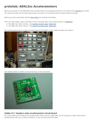
- 1. protolab: ADXL3xx Accelerometers We jus t purchas ed 10 new ADXL300-s eries accelerometers on prototyping-friendly carrier boards from Sparkfun for CS247. This document takes you through s tep-by-s tep ins tructions for connecting thes e accelerometers to d.tools . Before you s tart, get familiar with the Bas ic Rules for working in the iRoom. There are two models , which only differ in their s ens itivity (learn more about g forces at Wikipedia): The ADXL 322, which s ens es +-2g Sparkfun product page, Datas heet The ADXL 320, which s ens es +-5g Sparkfun product page, Datas heet The accelerometers live in a plas tic drawer labeled "ACCELERO" on the s oldering table in the iRoom: The model number is written on top of the chip, in the s econd line: Solder 0.1" headers onto accelerometer circuit board You could s older wire directly to the accelerometer board, but it's a good idea, out of courtes y for others who will the accelerometer after you, to add a connector, s o you can dis connect the cable.
- 2. The holes on the board have a s tandard s pacing - 0.1". We have matching header pins that come in long s trips in drawers ".1" HEADER" (s traight vers ion) and ".1" HDR ANGL" (90 degree angled vers ion). Take a s ingle row s trip of either kind and cut off four pins with a s ide cutter. Ins ert the header pins into the holes from VDD (s upply voltage - 5V in our cas e) through GND (ground), X, and Y. The chips we have do not s ens e acceleration in the Z -axis , s o we don't need to connect it. The remaining "ST" pin is for a s elf tes t, which we won't need either. Solder the pins in place - this is NOT a good time to practice s oldering. The s mall s urface mount accelerometer chip is heat s ens itive and it is pos s ible to overheat and kill it. Don't put the s oldering tip to the pin/pad for more than 2 or 3 s econds at a time. Read more about our Soldering irons .
- 3. The final outcome s hould look like this : Make a connecting cable We'll make a 4-wire connecting cable from ribbon cable. The color coding of the ribbon cable will help you identify the different wires later on. Peel off four conductors , s eparate their ends about 1", and s trip the ins ulation off about 1/4" us ing the 30 gauge hole of a wire s tripper.
- 5. Next, we'll crimp on female pins that match the headers we s oldered onto the board. You can find them in drawer labeled ".1" CRIMP PIN FEM". Break a few pins off. Ins ert one into the upper notch of the crimping tool, feed wire in, pres s down. Repeat. Read the Tutorial on crimping if you're unfamiliar with this operation.
- 6. Next, we'll have to ins ulate the pins from each other s o they don't caus e a s hort circuit. In drawer ".1" CONNECT HSNG" find a hous ing that fits four pins . Ins ert each crimped wire into a hous ing s lot until you hear a faint "click" - the wires s hould now be locked in place. s lide the connector onto the header pins - we're 2/3rds done.
- 7. Each analog d.tools component board has a 3-pin connector with the following connections (from left to right, if pins are at the bottom of the board): GND, Vin(input s ignal), VDD (s upply voltage - 5V). We now have to match up the connections between the d.tools board and the accelerometer board - GND to GND, VDD to VDD, and X to Vin. But wait, what about the Y axis ? You'll have to us e a s econd d.tools component and only connect the middle pin to the Y axis . Repeat the crimping for the other end of the cable, then ins ert VDD,GND,and one axis into a 3pin hous ing in the correct order. CAUTION: you will have to flip the order of the wires accordingly or you could ruin your accelerometer. In my example, the order of wire colors from left to right on the accelerometer is : Black (Y), White (X), Gray (GND), Purple (VCC). On the d.tools board, the order is : Gray (GND), White (X), Purple (VCC), with the Black wire going to the middle pin of another analogue d.tools component board.
- 8. Ins ert the s mall d.tools component boards into the large board, connect it to the PC, and watch your accelerometer data s tream into Exemplar or Flas h.