
Recommended
Recommended
More Related Content
What's hot
What's hot (20)
Viewers also liked
Viewers also liked (18)
Similar to Plan Symbols Guide
Similar to Plan Symbols Guide (20)
Recently uploaded
Recently uploaded (20)
Plan Symbols Guide
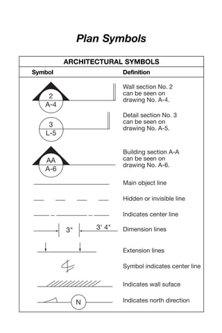
- 1. Plan Symbols 2 A-4 Wall section No. 2 can be seen on drawing No. A-4. 3 L-5 Detail section No. 3 can be seen on drawing No. A-5. AA A-6 Building section A-A can be seen on drawing No. A-6. Main object line Hidden or invisible line Indicates center line 3" 3' 4" Dimension lines Extension lines Symbol indicates center line Indicates wall suface N Indicates north direction ARCHITECTURAL SYMBOLS Symbol Definition 09 ConPal Dewalt 7/8/05 3:48 PM Page 1
- 2. ca 5 A 05 05 10'-0" 2 100'-0" 1 2 3 4 A-5 3 5or Column line grid Partition type Window type Door number Room number Ceiling height Revision marker Break in a continuous line Refer to note #3 Elevation marker Interior elevations 1,2,3 & 4 can be seen on drawing A-5. Direction of triangle indicates elevation. ARCHITECTURAL SYMBOLS (cont.) Symbol Definition 09 ConPal Dewalt 7/8/05 3:48 PM Page 2
- 3. Soil, waste or leader (above grade) Soil, waste or leader (below grade) Vent Combination waste and vent SV Acid waste AW Acid vent AV Indirect drain IW Storm drain S Soft cold water SW Industrialized cold water ICW Chilled drinking water supply DWS Industrialized hot water supply IHW Chilled drinking water return DWR Hot water Hot water return Cold water Sanitizing hot water return (180F) Sanitizing hot water supply (180F) PLUMBING PIPING 09ConPalDewalt7/8/053:48PMPage3
- 4. Industrialized hot water return IHR Tempered water supply TWS Tempered water return TWR Wet standpipe WSP Fire line F F Dry standpipe DSP Combination standpipe CSP Main supplies sprinkler S Branch and head sprinkler Gas – low pressure G G Gas – medium pressure MG Gas – high pressure HG Compressed air A Vacuum V Vacuum cleaning VC Oxygen O Nitrogen N Liquid oxygen LOX PLUMBING PIPING (cont.) 09ConPalDewalt7/8/053:48PMPage4
- 5. Liquid nitrogen LN Nitrous oxide NO Hydrogen H Helium HE Argon AR Liquid petroleum gas LPG Industrial waste INW Pneumatic tubes tube runs PN Cast iron CI Culvert pipe CP Clay tile CT Ductile iron DI Reinforced concrete RCP Drain – open tile or agricultural tile 09ConPalDewalt7/8/053:48PMPage5
- 6. High pressure steam HPS Medium pressure steam MPS Low pressure steam LPS High pressure return HPR Medium pressure return MPR Low pressure return LPR Boiler blow off BD Condensate or vacuum pump discharge VPD Feedwater pump discharge PPD Make up water MU Air relief line V Fuel oil suction FOS Fuel oil return FOR Fuel oil vent FOV Compressed air A Hot water heating supply HW Hot water heating return HW HEATING PIPING 09ConPalDewalt7/8/053:48PMPage6
- 7. Refrigerant suction RS Condenser water supply CWS Condenser water return CWR Chilled water supply CHWS Chilled water return CHWR Make up water MU Humidification line H Drain D Brine supply B Brine return BR RDRefrigerant discharge Refrigerant liquid RL AIR CONDITIONING PIPING 09ConPalDewalt7/8/053:48PMPage7
- 8. T Up/Down Gate Expansion loop Flexible connection Thermostat Thermostatic trap Globe Check Butterfly Solenoid Lock shield 2-Way automatic control 3-Way automatic control Gas cock Plug cock Flanged joint Union Cap Strainer Concentric reducer Eccentric reducer Pipe guide Pipe anchor Flow direction Elbow looking up Elbow looking down Pipe pitch up or down Expansion joint Valves, Fittings and Specialties PIPING SYMBOLS 09 ConPal Dewalt 7/8/05 3:48 PM Page 8
- 9. F&T H A P FS M IW S S Float and thermostatic trap Thermometer Pressure gauge Flow switch Pressure switch Pressure reducing valve Temperature and pressure relief valve Humidistat Aquastat Air vent Meter Hose bibb 'Y' OS & Y gate Indirect waste Sanitary below grade Sanitary above grade Shock absorber House trap ‘P’ trap Floor drain Elbow Tee PIPING SYMBOLS (cont.) 09 ConPal Dewalt 7/8/05 3:48 PM Page 9
- 10. DWRDrinking water return CW N2 OCold water Nitrous oxide HW OHot water Oxygen HWC LOX Hot water circulation Liquid oxygen DWS LPGDrinking water supply Liquid petroleum gas AW VVacuumAcid waste below grade AW VCVacuum cleaning Acid waste above grade AV NNitrogenAcid vent MG Gas-medium pressure ST Storm above grade HG Gas-high pressure Vent CA Compressed air CWV Combination waste & vent G Gas-low pressureST Storm below grade PIPING SYMBOLS (cont.) 09 ConPal Dewalt 7/8/05 3:48 PM Page 10
- 11. WSP DSP CSP SP FHR FHC FHC Fire hydrant Sidewalk fire department connection Fire hose rock Surface mounted fire hose cabinet Recessed fire hose cabinet Wet standpipe Dry standpipe Combination standpipe Automatic fire sprinkler Upright fire sprinkler heads Pendent fire sprinkler heads FFire protection water supply Wall fire department connection FIRE PROTECTION PIPING SYMBOLS 09 ConPal Dewalt 7/8/05 3:48 PM Page 11
- 12. Vanity Wall Counter Pedestal Lavatories Corner Recessed Angle Whirlpool Institutional or island Baths Stall Corner Stall Wall Gang Showers Tank Flush Valve Water Closets Wall Stall Trough Urinals Bidet PLUMBING FIXTURE SYMBOLS 09 ConPal Dewalt 7/8/05 3:48 PM Page 12
- 13. SSSS L TLT Single Double Wall Floor Laundry Trays Service Sinks Wash Fountains SeparatorsHot Water HWTHW WFWF Circular Semicircular Gas Oil Heater Tank G O Single basin Twin basin Floor or wall Recessed Semirecessed Single drainboard Double drainboard Kitchen Sinks Dishwasher Drinking Fountains or Electric Water Coolers DFDFDF DW PLUMBING FIXTURE SYMBOLS (cont.) 09 ConPal Dewalt 7/8/05 3:48 PM Page 13
- 14. Cut RubbleCut RubbleRubble Common Face or common Siding Panel Framing Finish Face Floor areas left blank Wood Material Plan Elevation Section Brick Stone Same as plan view Cut MATERIAL INDICATION SYMBOLS 09ConPalDewalt7/8/053:48PMPage14
- 15. Concrete Earth Glass None None Insulation Concrete block Same as plan view Same as plan view Same as section Insulation Loose fill or batt Small scale Large scale Board 09ConPalDewalt7/8/053:48PMPage15
- 16. Sheet metal flashing Indicate by note Show contour Structural steel Indicate by note Material Plan Elevation Section Plaster Same as section Stud Lath and plaster Plaster MATERIAL INDICATION SYMBOLS (cont.) 09ConPalDewalt7/8/053:48PMPage16
- 17. Tile Floor Wall Plywood Indicated by note Indicated by note Porous fill NoneNone 9-17 09ConPalDewalt7/8/053:48PMPage17
- 18. Material Plan Elevation Section Batt insulation Rigid insulation Glass Small scale Large scale Same as planNone None Same as plan MATERIAL INDICATION SYMBOLS (cont.) 09ConPalDewalt7/8/053:48PMPage18
- 19. Gypsum wallboard Acoustical None Floor tile None Same as plan Ceramic wall tile Same as plan 09ConPalDewalt7/8/053:48PMPage19
- 20. Property line Center line Building Window Door Paving — Wall Stone wall Hedge Fence Concrete Sand Brick Gravel Rock Water Swamp pattern random LANDSCAPE SYSTEMS AND GRAPHICS 09 ConPal Dewalt 7/8/05 3:48 PM Page 20
- 21. Slope Steps Trees — Shrubs — Herbaceous plants (flowers) Same variety Grass Ground cover Benchmark Topographic contours Contour lines — up up down evergreen deciduous unaltered altered proposed 10 5 EI.00.0 evergreen deciduous down LANDSCAPE SYSTEMS AND GRAPHICS (cont.) 09 ConPal Dewalt 7/8/05 3:48 PM Page 21
- 22. Masonry Adobe/rammed earth Common/face Earth/compact fill Cast-in-place/precast Porous fill/gravel Lightweight Concrete block Gypsum block Fire brick Structural facing tile Rock Sand/mortar/ plaster/cut stone Earthworks Concrete MATERIALS SYMBOLS 09ConPalDewalt7/8/053:48PMPage22
- 23. Aluminum Rubble Marble Metal Brass/bronze Steel/other metals Finish Wood Rough Blocking Hardboard Plywood – large scale Plywood – small scale Bluestone/slate/ soapstone/flagging Stone 09ConPalDewalt7/8/053:48PMPage23
- 24. Finishes Acoustical tile Ceramic tile – large scale Glass Batt/loose fill Structural Rigid Carpet and pad Gypsum wallboard Ceramic tile – small scale Metal lath and plaster Glass block Spray/foam Glass Insulation MATERIALS SYMBOLS (cont.) 09ConPalDewalt7/8/053:48PMPage24
- 25. Wood stud Resilient flooring/plastic laminate Terrazzo Plan and Section Indications Partition Indications Metal stud Special finish face Brick Elevation Indications Ceramic tile Concrete/plaster Glass Sheet metal Shingles/siding Plastic Finishes (cont.) 09ConPalDewalt7/8/053:48PMPage25
- 26. Double hung windows Casement windows Slider indicates window hinge Type Plan Elevation WINDOW AND DOOR SYMBOLS 09ConPalDewalt7/8/053:48PMPage26
- 28. Double hung windows Double unit casement windows Partition Fixed glass Fixed glassAwning and hopper Alternate double hung window Alternate frame wall symbols Door Door Openings in Frame Wall Openings in Brick Veneer Wall WINDOW AND DOOR SYMBOLS (cont.) 09ConPalDewalt7/8/053:48PMPage28
- 29. 2 units double hung windows Arch Pocket sliding door Double action door Interior door Bypass sliding door Bifold doors Accordion door Sliding doors Door Alternate position Openings in Masonry Wall Openings in Interior Partitions 09ConPalDewalt7/8/053:48PMPage29
- 30. Graphic Symbols N Up 17R Stair direction symbol Indication arrows drawn with straight lines (not curved); must touch object Note Note Note North point to be placed on each floor plan, generally in lower right hand corner of drawings 111 /2 T The symbols shown are those that seem to be the most common and acceptable, judged by the frequency of use by the architectural offices surveyed. This list can and should be expanded by each office to include symbols generally used by it, but not indicated here. Adoption of these symbols as standard practice is desirable to improve communication in the industry. DRAWING CONVENTIONS AND SYMBOLS 09 ConPal Dewalt 7/8/05 3:48 PM Page 30
- 31. C A-3 I I A-3 3 A-1 7 A-5 9 A-4 5 A-8 C A-3 Indicates section number Indicates detail number Indicates drawing sheet on which detail is shown Indicates drawing sheet on which section is shown DRAWING CONVENTIONS AND SYMBOLS (cont.) Detail References Section Lines and Section References 09 ConPal Dewalt 7/8/05 3:48 PM Page 31
- 32. New or required point elevation Building section Reference drawing number Wall section or elevation Reference drawing number Existing point elevation (plan) 461.0' 461.0' Test boring New contours elevation noted on high side Existing contours elevation noted on high side TB-1 268 320 C A-9 7 A-11 Detail Reference drawing number Room/space number Equipment number 7 A-12 1302 354 DRAWING CONVENTIONS AND SYMBOLS (cont.) 09ConPalDewalt7/8/053:48PMPage32
- 33. Match line shaded portions – the side considered 3 E A 4 Level line control point or datum Revision Window type Column reference grids Project north (magnetic north arrow used on plot site plan only) Door number (if more than one door per room subscript letters are used) N 123 B Magnorth 09ConPalDewalt7/8/053:48PMPage33
- 34. Dimension Lines Dash and dot Center lines, projections, existing elevations lines Dash and double dot line Property lines, boundary lines Dotted line Hidden, future or existing construction to be removed Break line To break off parts of drawing Slash Horizontal Vertical 4' 0" 5' 4" 1 /2" 8" 2" 4'0" 6'2" 2' 8" 26' 8" 8' 1 /2" 63 /4" 4" Arrow Dot Accent DRAWING CONVENTIONS AND SYMBOLS (cont.) Linework 09 ConPal Dewalt 7/8/05 3:48 PM Page 34