Design and Analysis of Mechanism for Dynamic Characterization of Power Transm...
Fondasi Untuk Mesin Pembuat Kertas
1. Dynamic analysis ofpa.. machine foundations
Sauren Guha-Majumdarand Makram A Khoury
fats w h p a p e r m b i n e s have &d F m i c anabszj of mbinefounhtions
a routinepart of the design process. Tbzi bas created an urgent needfir indmrywzdeguidelines
covering tbe use of tbzj design tool.
The rotating rolls in today’s high-speed fine paper machines Machinewidths also have increased to accommodate demands
can initiate dynamicexcitationwithin a frequency range of 2-20 for higher productivity.Fine paper machines are being manufac-
Hz. Dynamic and static analyses of the machine and its support turedwith widths exceeding400 in. Wider machinesimply heavier
structure are essential if the machine is to run smoothly,thereby machine components and sill beams. Since system frequency is
reducing the number of shutdowns, the amount of off-quality inversely proportional to the square root of the mass, heavier
production, and maintenance costs. The advent of fast, high- componentswill result in a lower system frequency
capacity, cost-efficient computers has made it possible to ana- Increases in machine speed and width have made it difficult
lyze the interaction between complex machines and their support t achieve a high-tuned system, i.e., a system whose first natu-
o
structures. ral frequency is higher than the excitation of the highest roll
A fine paper machine generally comprises the following frequency at the highest machine speed (for a roll of significant
sections: wire, press, dryer, size press, calender and reel, and mass). Consequently, the machine-foundation system will, in
winder. The machine foundation includes the structural ele- many cases, have to be designed to operate under resonant
ments below the machine sole plates: sill beams, cross beams, conditions.
columns,walls, and the building foundation,including the soil or
pile support. In this paper, the combined machine and founda- Data requirements
tion is defined as a system.
The machine manufacturer and the consulting engineer re- Machine manufacturers develop technical data, including vi-
sponsible for designing the machine’s foundation must thor- bration criteria and an analytical model, for each machine sec-
oughly understand each other’s analyses and work closely to tion. The consulting engineer must have access to this
construct a structurally sound system at the lowest cost. This information in order to design an effective and efficient founda-
article outlines the information requirements for dynamic analy- tion for the paper machine.
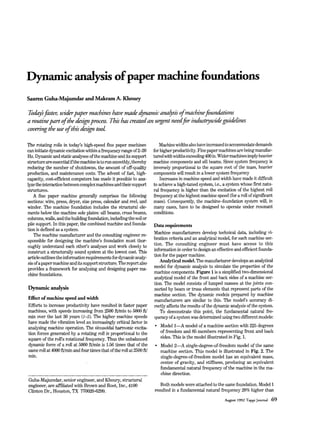
sis of a paper machine and its support structure. The report also Analytical model. The manufacturer develops an analytical
provides a framework for analyzing and designing paper ma- model for dynamic analysis to simulate the properties of the
chine foundations. machine components.Figure 1 is a simplified two-dimensional
analytical model of the front and back sides of a machine sec-
tion. The model consists of lumped masses at the joints con-
Dynamic analysis nected by beam or truss elements that represent parts of the
machine section. The dynamic models prepared by machine
Effect of machine speed and width manufacturers are similar to this. The model’s accuracy di-
Efforts to increase productivity have resulted in faster paper rectly affects the results of the dynamic analysis of the system.
machines, with speeds increasing from 2500 ft/min to 5000 ft/ To demonstrate this point, the fundamental natural fre-
min over the last 30 years (1-5). The higher machine speeds quency of a system was determined using two different models:
have made the vibration level an increasingly critical factor in
analyzing machine operation. The sinusoidal hannonic excita- Model 1-A model of a machine section with 225 degrees
tion forces generated by a rotating roll is proportional to the of freedom and 85 members representing front and back
square of the roll’s rotational frequency. Thus the unbalanced sides. This is the model illustrated in Fig. 1.
dynamic force of a roll at 5000 ft/min is 1.56 times that of the Model 2-A single-degree-of-freedom model of the same
same roll at 4000 ft/min and four times that of the roll at 2500 ft/ machine section. This model is illustrated in Fig. 2. The
min. single-degree-of-freedom model has an equivalent mass,
center of gravity, and stiffness, producing an equivalent
fundamental natural frequency of the machine in the ma-
chine direction.
Guha-Majumdar, senior engineer, and Khoury, structural
engineer, are affiliated with Brown and Root, Inc., 4100 Both models were attached to the same foundation. Model 1
Clinton Dr., Houston, TX 770020-6299. resulted in a fundamental natural frequency 20% higher than
August 1992 Tappi Journal 69
2. 1. Machine Model 1, with 225 degrees of freedom
Model 2. Thus Model 2 would produce (a) a conservative and 2. Machine Model 2, single-degree-of-freedom system. El is rigidity of
expensive foundation for a high-tuned system or (b) an unsafe member, and 144.31 in. is the location of center of gravity of machine
foundation for a low-tuned system, i.e., a system whose first mass.
natural frequency is lower than the excitation of the lowest roll I
frequency at the lowest machine speed.
In a force-response analysis, the results from Model 2 would
have been unreliable. Although this difference in frequency was
obtained for a particular case, a simplified single degree of
freedom representing a machine section will generally yield a
A
lower frequency. Model 1detected coupled modes that would be
missed in a model with a single degree of freedom. Given these
results, it is imperative that machine manufacturers provide a
detailed representative model of each machine section.
Damping ratios. Damping dissipates the energy in a vibrat-
El 144.31 in.
ing system by suppressing vibratory motion. Energy is often
dissipated in the form of heat loss. The dissipation of vibratory
energy reduces the amplitude of vibration and makes it possible
to operate a system even if it is in resonance.
The damping ratio is the actual resistance in damped har-
monic motion to that necessary to produce critical damping. In
order to perform a force-response analysis, it is necessary to
//A ///
v
know the damping ratio of the system or its components (5).In
the structural analysis, damping is in the form of dry friction
and hysteresis loss, which are not well understood and therefore
are approximated. Measurement of vibration amplitudes of op-
High-tuned OT low-tuned system In a high-tuned system,
erating machines will help determine the damping ratios of
the first natural frequency of the system is higher than the
general paper machine components and systems. Such informa-
excitation of the highest roll frequency at the highest machine
tion will be helpful for future designs. speed (for a roll of s i m c a n t mass). In a low-tuned system, the
The manufacturer provides the consulting engineer with the first natural frequency of the system is lower than the excitation
damping ratio for the machine. The effect of damping is illus- of the lowest roll frequency at the lowest machine speed. Excita-
trated in Fig. 3 (6), where the dynamic magnification factors are tion frequencies are determined using Eq. 1.
substantially higher for frequency ratios in the range of 0.75-
1.25,especially where system damping ratios are low. The mag- J = 12S/60D,n (1)
nification factor, or dynamic load amplificationfactor, increases where
by a factor of up to 50 for a damping ratio of 1%.
Vibration criteria. Vibration analysis is done in the three f i = excitation frequency U; = highest,& = lowest), Hz
principal axes of each machine section. Vibration criteria differ
for each of the following situations: Dz = roll diameter (D1= smallest, D, = largest), in.
St = design speed (SI= highest, S, = lowest), ft/min
High-tuned or low-tuned system
Manufacturers commonly recommend the following criteria
System in resonance.
for the vertical frequency U;)and horizontal frequency g) the of
system:
70 August 1992 Tappi Journal
3. f , > 2% each roll. A conservative approach is to add the absolute response
of the two rolls.
J , > 1.2%or < 0.7%
For a system satisfying the high-tuned criteria, a force- Designing the bundation
response analysis is generally not required because of the ex-
cellent track record of machine performance. The structural engineer must satisfy both static and dynamic
Operating speeds for h e paper machines typically range requirements while resolving layout problems.
from 2500 Wmin to 4500 "in. The excitation frequency of a
38h-diam. roll ranges from 4.19 Hz to 7.55 Hz for this speed static analysis
range, while the excitation frequency of a Win.-diam. roll ranges
from 2.65 Hz to 4.78 Hz. In a machine section c o n t a i i g both The consulting engineer applies the loads provided by the manu-
38-in. and 60-in. rolls, excitation frequencies can range from facturer at the specified locations. Analysis is performed using
2.65 Hz to 7.55 Hz. Using the design-criteria factors of 0.7 and commonly availablefinite-elementcomputer software (10-13). The
1.2 for horizontal frequency, the design range in the machine concrete and steel members of the foundation are designed to
direction would be 1.86 Hz to 9.06 Hz. Based on our experience, comply with ACI (14) and ASCE (15) codes and to meet the
the fundamental natural frequency of a system ranges from 3 manufacturer's deflection criteria (16).
Hz to 7 Hz, depending on the machine and foundation proper- Several factors are considered in the analysis and design of the
ties. Resonant conditions prevail at different production rates foundations:
with different machine rolls. Shear deformation (especially when depth-to-span ratio is
small)
System in resonance. In addition to a model, damping ratio,
and pseudodynamic loading of each machine section, the follow- Properties of uncracked concrete sections (when the level of
ing information is needed to perform a force-response analysis stress is low)
of the system: Clear span-the effective length of the beam-and the use of
Forcing function rigid links at joints where structural members overlap
Vibration amplitude Design of sill beams using deep-beam theory.
Phase angle.
Isolation of machine sections
1. Forcing function: The design criteria include the unbal- Designers have not always routinely performed dynamic analyses
anced force for each roll at different machine-speed intervals. of paper machine systems. The need was not as compelling as it is
The unbalanced forces represent dynamic time-dependent ex- on today's high-speed machines, and analysis was complicated by
citation on the machine components that the industry will toler- the widespread practice of attaching machine foundations to the
ate, considering the effect on equipmentwear and paper quality. operating floor.
The exciting force, F, for an unbalanced rotating mass is given Foundations for modern paper machines are not connected to
in Eq.2. the operating floor, and the foundation for each machine section is
typically isolated from the others. Isolation eliminates transmis-
F = med[sin(wt + @)] (2) sion of vibration between the building and the machine sections
where and from one section to another. Isolation of the dryer sections
also helps control deflection from thermal expansion (3).
m = unbalanced rotating mass
e = eccentricity of unbalanced mass Frequency analysis
o = angular frequency of the roll The consulting engineer must satisfy the frequency requirements
specified by the machine manufacturer. The first step in this
t =time process is to perform a frequency analysis on the combined ana-
Q = phase angle of the rotating mass lytical model of the machine, its support structure, and the founda-
tion piles (or the soil). For a rigid foundation supported on soil, the
2. Vibration amplitude: For each machine section, this crite- equivalent spring constants and damping ratios can be obtained
rion specifies allowable vibration amplitudes at critical loca- from Tables 10-13 and 10-14 of Richart et al. (17). The spring
tions. Limits for vibration of general rotating machinery are constants for piles or shear modulus of soil are determined by soil
shown in Fig. 4 (7, 8), where the upper line in zone B is the consultants. Methods of interpreting field test are described by
allowable vibration amplitude. Similar vibration criteria are Richart et al. (17).
needed for the pulp and paper industry. A three-dimensional analytical model is recommended in cases
3. Phase angle: The phase angle specifies the time relation- where geometry and mass distribution are asymmetrical. If the
ship between two rolls with the same frequency rotating such fundamental frequency of the system is much higher than 1.2
that their peak values of the same sign (positive or negative) do times the highest excitation frequency, cost can be reduced by
not occur simultaneously (6, 9). A common statistical approach reducing the stiffness of the structure. If frequency criteria are not
is to use the square root of the sum of squares of responses of met, a force-response analysis is performed.
August 1992 Tappi Journal 71
4. 3. Vibration magnification factor as a function of frequency ratio 4. Peak horizontal vibration amplitude (measured at the bearing) as a
(excitation frequencyhatural frequency) at various levels of damping function of rotational frequency. Upper limit of zone B is the maximum
(0) allowable amplitude for general rotating machinery.
50 1 I
40
30
20
10
0.01
8
6
.-
s
Mi
5 P
4 3
3 t
A
n
2 I
c[
Y
1.o s
a.
0.8 0.001
0.6
0.5
0.4
0.3
0.2 - D = 0.60
1 1 1 1 I I I I
0”
.
100 1000 r,
om
FREQUENCY, cycleslmin
Force-responseanalysis ses are performed for each exciting roll, and the response is
Dynamic loading and the steady-state response of each ma- measured at the required locations. Since the analysis is linear,
chine section is harmonic and sinusoidal. The displacements, the method of superposition is used to determine the final
velocities, or accelerations at or near resonance are obtained response.
from a force-response analysis. The equation of dynamic equi- In finite-element analysis, a damping matrix is created to
librium solved in a harmonic-response analysis is given in Eq. 3: solve the response of the time-related dynamic forcing function.
A common method (9, 18) is to combine a fraction, a,of the
{FI= [Iwl{O”l+ [Cl{O’l + [KJ{D) (3) stiffness matrix with a fraction, p, of the mass matrix, shown in
where Eq. 4 .
{ F } = load amplitude vector [cl=C m + P[Ml (4)
[MI =massmatrix Equation 4 is the Rayleigh or the proportional damping.
With this damping matrix, the set of second-order differential
[a = dampingmatrix
equations described are linear, and the mode shapes are
[KJ = stiffness matrix decoupled. If p = 0, the higher modes are lightly damped. If a =
0, the higher modes are heavily damped. The term a is the
(D’
’} = acceleration vector
dominating factor in dynamic analysis of machine systems,
{D’} = velocityvector since the excitation is close to the first few natural frequencies
of the system. The stiffness of the system is the most critical
{D} = displacement vector
factor in determiningvibration amplitude.
Mathematically, the equation represents a series of second- The damping ratio can be incorporated in the computer
order differential equations. Some commonly used computer analysis by one of the following two methods.
programs for performing force-response analysis are STRUDL, Method 1-Perform force-response analysis of the system
NASTRAN, ANSYS, and SAP (10-13’). System response is using the lowest damping ratio, i.e., the damping ratio of the
determined over the frequency range that corresponds to the machine’s steel frame and steel support base frame. This damp-
operatingrange of the roll under consideration.Separate analy- ing ratio, 0.5-1%, will yield conservative results. Method 1 is
recommended for structures supportedwith a steel base frame.
72 August 1992 Tappi Journal
5. Method M a m e as Method 1,except damping ratios of each 8. Mechanical vibration of machines with operating speeds from 10 to
system element are specified. Concrete damping is in the range ZOOrev/s-Basisfor spec@ing evaluationstandards, 1902372-1974(3),
International Standards Organization, 1974.
of 3-5%, while soil damping can be as high as 50%(17).Method 2 9. Hurty, W. C., and Rubinstein, M. F., Dynamics of Structures, Prentice
is recommended unless restricted by computer capacity. Hall, Englewood Cliffs, NJ, 1964.
10. Structural Design Language (STRUDL) computer program, Massa-
chusetts Institute of Technology, Department of Civil Engineering,
Conclusion Cambridge, MA.
11. NASA Structural Analysis (NASTRAN) computer program, NASA
The quest for greater productivity has led to the development SP-222, National Aeronautics and Space Administration, Goddard
of faster, wider paper machines, and this trend is likely to Space Flight Center, Greenbelt, MD.
12. Engineering Analysis System (ANSYS)computer program, Swanson
continue. Efficient operation of today’s high-speed paper ma- Analysis Systems, Houston, PA.
chines requires a well-designed foundation that can sustain 13. Wilson, E. L., et al., Structural Analysis Program (SAP) computer
vibration within a tolerable range. Dynamic considerationstend program, University of California, Berkeley.
to determine the sizes of major components of the foundation. 14. Building code requirements of reinforced concrete, ACI 318-89; and
Commentary, ACI 318R-89, American Concrete Institute, Detroit,
Dynamic analysis, in turn, has become an essential part of the 1989.
design process. 15. Manual of Steel Construction (9th edn.), American Institute of Steel
The analysis is elaborate and requires close interaction be- Construction, Chicago, 1989, pp.5.1-5.195.
16. Machinebuilding interface design considerations,K095-96-0101-0001,
tween the machine manufacturer and the consulting engineer Beloit Corp., Beloit, WI.
responsible for designing the machine’s foundation. This is 17. Richart, F. E., Hall, J. R., and Woods, R. D., Vibration of Soils and
especially true for machines whose speed and width stimulate Foundations, Prentice Hall, Englewood Cliffs, NJ, 1970, pp.191-243.
roll frequencies that are in resonance with system frequency. A 18. Cook, R. D., Concepts and Applications of Finite Element Analysis
(2nd edn.), John Wiley & Sons, New York, pp. 302-25.
high-tuned system is preferable and provides the safest design,
but a force-response analysis is imperative in low-tuned and Received for review May 31,1991.
resonant conditions.
Models of the machine and foundation are required to deter- Accepted Feb. 19,1992.
mine frequencies and vibration amplitudes. An adequate model
with sufficientmass points is essential to obtain accurate results. Keywords: Analysis, damping, dynamic tests, force, foundations, high veloc-
The model can be reduced in size only if the engineer thoroughly ity, models, paper machines, resonance, response time, standards, vibration.
understands the system response. Reducing a machine model to
a single degree of freedom results in unreliable output.
The recommended practice is to isolate each machine section
with a separate foundation and to isolate each of these founda-
tions from the operating floor. Isolation prevents transmission
of vibrations from one section to another and between the
building and the paper machine. Isolation also makes the size
and the cost of the dynamic analysis manageable.
The pulp and paper industry urgently needs standardized
criteria to streamline the task of analyzing and designing paper
machines and their foundations. A good starting point would be
development of guidelines for frequency analysis, force-re-
sponse analysis, forcing function, vibration amplitude, damp-
ing, and phase angle of response.
Studiesinvolvingfield measurementson operating machines
are needed to determine acceptable limits of machine opera-
tion. Such studies would best be canied out by committees
consisting of papermakers, machine manufacturers, and con-
sulting engineers. The TAPPI committee on paper machine
dynamic foundation design would be a good candidate for un-
dertaking this essential task. 0
Literature cited
1. McKevitt, W. E., Pulp Paper 40(7): 82(1987).
2. Roisum, D. R., Tappi J. 71(1): 87(1988).
3. Baldwin, J.W., Bonnet, H. P., and Reis, W. W., TappiSl(10): 75A(1968).
4. Lee, J. P., Proceedings of Second International Conference on Recent
Advances in Geotechnical Earthquake Engineering and Soil Dynam-
ics, Vol. 11, ( .
S Prakash, Ed.), Rolla, MI, March 1991, pp. 1525-30.
5. Abdulezer, A., and Clark, K. B., Pulp Paper Can. 88(5):lll(1987).
6. Arya, S.C., O’Neill, M. W., and Pincus, G., Design of Structures and
Foundations for Vibrating Machines, Gulf Publishing, Houston, TX,1979.
7. Blake, M. P., Hydrocarbon Processing Petroleum Refiner 43(1):
11l(1964).
August 1992 Tappi Journal 73