Gas Air Heater (Air Pre Heater)

The document discusses a regenerative air preheater (GAH) used at a power plant. It contains specifications for the GAH such as its size, heating surface areas, temperatures, and pressure drops. The GAH uses a rotating cylinder filled with heating elements to transfer heat from flue gases to combustion air. It helps increase boiler efficiency. However, leakage of air through the seals is an inherent issue. The document examines various paths and causes of leakage, including thermal expansion differences between the hot and cold ends of the rotor. It notes the importance of properly setting seals to account for this "turn down" and minimizing gaps between sealing surfaces. Excessive leakage reduces efficiency and increases heat rate and power consumption.

Recommended
Recommended
More Related Content
What's hot
What's hot (20)
Viewers also liked
Viewers also liked (20)
Similar to Gas Air Heater (Air Pre Heater)
Similar to Gas Air Heater (Air Pre Heater) (20)
Recently uploaded
Recently uploaded (20)
Gas Air Heater (Air Pre Heater)
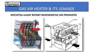
- 1. GAS AIR HEATER & ITS LEAKAGE NITCHITSU-LUGAT ROTARY REGENERATIVE AIR PREHEATER
- 2. Gas Air Heater (CH8.2/1.175+0.3C): Introduction: The Air Preheater at Hub is a Regenerative type Rotary heat exchanger in which flue gases and air passes through a rotating cylinder/rotor filled with heat transfer surfaces (heating elements).The flue gas heat the rotating elements, which in turn preheat the air before it is fed to the boiler.
- 3. Contd • The higher the exit flue gas temperature the higher will be the boiler heat loss / efficiency loss. Therefore air pre heater is to recover the sensible heat from the boiler flue gas exiting the economizer which increases the thermal efficiency of the boiler by reducing the useful heat lost in the flue gas. • Heating combustion air can raise boiler efficiency about 1% for every 22°C in temperature increase of combustion air. • It may be Bi-Sector , Tri Sector etc. At Hub GAH is a bi-sector containing air and flue gas .The rotor is supported at both ends with a roller Bearing.
- 4. GAH AT HUB SPECIFICATIONS: MANUFACTURER NITCHITSU-LUGAT AIR PRE-HEATER NUMBER 2SETS /BOILER SIZE CH8.2 /1.175 + 0.3C HEATING SURFACE: GAS SIDE : 17554 m2 AIR SIDE: 17554 m2 INLET GAS TEMPERATURE 350 OC OUTLET GAS TEMPERATURE 152 OC INLET AIR TEMP 74OC OUTLET AIR TEMP 309OC DUCT ARRANGEMENT GAS OVER AIR AIR LEAKAGE 7 % (MCR) HOT END LAYER: MATERIAL: MILD STEEL ELEMENT DEPTH 1175 mm THICKNESS: 0.5mm EXCESS AIR LEAVING BOILER 5.00% COLD END LAYER: MATERIAL: CRLS ELEMENT DEPTH 300 mm THICKNESS: 1mm PRESSURE DROP AIR SIDE 100 mm Aq GAS SIDE 120 mm Aq BEARINGS 2 SELF ALLIGNING ROLLER BEARING
- 5. Components: Hot End Element Cold End Element Sector Plate Radial Seals Circumferential Seals Hub Seals
- 6. Hot End/Cold End Elements:
- 7. Heating Element Types Hot End Elements: (DU Profile): The DU (double Undulated design is widely used in hot and intermediate elements. The common characteristic of DU elements is the alternating stacking of undulated elements sheets with sheets that contain both undulations and notches
- 8. Heating Elements Types: CU Element: CU (Corrugated Undulated) elements are a compact highly thermal efficient element but with correspondingly high pressure drop characteristics as well.
- 9. Circumferential Seals Circumferential seals are located on the entire circumference of the air heater rotor, on both the hot end and cold end of the air heater.
- 10. Radial Seals: Radial seal leakage is the mass of inlet air that leaks through the air heater seals into the gas outlet stream.
- 11. Heating Elements: Mechanical Consideration: There are many different options when it comes to choosing a heat exchanger element design. Each configuration has its own unique pressure drop and heat transfer characteristics. For example, an element that is designed to achieve maximum heat transfer in a limited amount of space (depth) may also have a higher overall pressure drop than an element design that requires a greater depth to achieve the equivalent heat transfer. and vice versa.
- 12. GAH leakages: As a rule of thumb For a horizontal-shaft APH, approximately two-thirds of air leakage occurs at the CE. Air heater leakage can occur from different paths. • Path 1: Normal air flow path • Path 2: Normal gas flow path • Path A: Ambient FD fan leaking directly to the APH Gas Outlet • Path B: Pre-heated FD fan air flow short circuiting the APH • Path C: Ambient FD fan air leaking around AH. • Path D: Hot gas exiting boiler
- 13. Pressure Differential: There is a Pressure Differential Exist between the FD fan outlet air and the incoming Flue Gas .FD fan air Being pressurized tries to find a way towards lower pressure side. That is why there is a inherent Leakage exist in Rotary regenerative Gas air heater.
- 14. Path A: Cold Radial Leakage
- 15. Path B Hot Radial Seal Leakage
- 16. Path C: Circumferential Seal Leakage
- 17. Path D: Circumferential Leak
- 19. Impact On Plant Performance: • Air heater responsible for at least 10% of a units thermal efficiency. • Excessive leakage can deteriorate net unit efficiency as well as reduce power generation. • GAH leakage Increases heat rate. Its major drawback of regenerative air heater is the undesired leakage that is inherent in its design. Also the GAH leakage will cause more power consumption as more volume of a air is required from FD fan.
- 20. Power Consumption (FD) Vs Volumetric Flow
- 21. Causes Of Leakage: • Major causes of GAH leakage is the large temperature difference between its hot and cold end elements. These opposing temperature gradients work together to produce a significant radial thermal expansion difference between the hot and cold sides of the air heaters rotor after unit start up. Due to this inherent thermal distortion, it's not uncommon for the outer edges of a large air heater at operating temperature to experience a significant "droop" (or "turn down"). The distortion caused by this thermal turndown (which can be as much as 4 inches on some rotors) changes the gaps between the seals and the sealing surfaces as the rotor warms to operating temperature, and is the most significant contributor to air heater leakage. This phenomenon must be accounted for when setting the seals at a cold state, That’s why it is stated that Seals are to be set, not only to be fitted.
- 22. Turn Down: Clearance between the radial seal and stationary sector plate is zero on hot end .while on cold end this clearance is zero at the inner circumference and 10mm at the outer circumference. Cold Top View
- 23. Contd • Non Uniform Thickness of Sector Plate .Resulting in gap between Radial Seal and plate due to Corrosion. • Improper functioning of Sliding foots. • Due to temperature fatigue a permanent deformation may occur causing undesirable seal gaps causing excess leakage. At Cold condition the gaps between the sector plate and the Radial seal plate at the sector plate corner and the hub side are not the same. Therefore the radial seals are fit firstly at the location where Gap is minimum.
- 24. Sliding Foots: Top View
- 25. How to reduce Leakage • Whenever there is unevenness and distortion in the sealing surfaces (sector plates), as is commonly found in older air heaters. They lead to “distortion gaps” which are significant contributor to the high leakage that are mostly found in old air heaters. • If rotor Expansion , casing expansion matches with the seal clearances then leakage would be minimize. • Actual Droop Measurement. (How much Hot end Moves Toward the Cold end from the edges ?). • Using Sacrificial Radial Seal to measure the Actual expansion during the Unit Operation. • Recommended angles of the Radial Seal Plates are according to our requirement./or not?