SlideShare une entreprise Scribd logo
1  sur  26
Safety and Safety Management                     MSc Applied Instrumentation &Control


                                   Contents
Coursework 1
1. Introduction
   1.1.The Process
   1.2. Explosive atmosphere
   1.3. Zones
   1.4. Equipments
2.Risk Assessment
   2.1.Identify People at Risk

   2.2. Hazard associated with plan area

   2.3. Risk evaluation and severity

   2.4. Control Measures

   2.5. Actions

3.Legislations


Coursework 2
1.Introduction

2.Instrumentation System in Safety respect

   2.1.Instrumentation System Design

3. Control System recommendations
4.Proposed Instrumentation system Architecture

5.Legislation in selecting Equipments


References


         School of Engineering, Science & Design ,Glasgow Caledonian University
                                             1
Safety and Safety Management                     MSc Applied Instrumentation &Control


Coursework 1:Risk Assessment for Fire and Explosion Hazards and
associated Legislations
This report firstly describes the risks for fire and explosion hazards in a pneumatic
conveying system of a pharmaceutical powder called Pharmex.Secondly ,it outlines the
related legislation for the given process.


         Figure 1: Schematic diagram of the Pneumatic conveying system.


         School of Engineering, Science & Design ,Glasgow Caledonian University
                                             2
Safety and Safety Management                      MSc Applied Instrumentation &Control


1. Introduction
The purpose of this risk assessment is to identify and evaluate the fir & explosion
hazards before the operation of the process. Control Of Substances Hazardous to
Health (COSHH) regulations is a useful tool for this work. The motivation for this
assessment arises from the fact that the employees should be prevented from exposure
to hazards. Indeed, the implementation of COSHH regulations leads to
 i) higher productivity as a result of using more effective controls, ii) improved
employee morale.
Actually in the risk assessment of fir and explosion we will try to find out where there
is enough powder that would give us explosion.Whenever powder in the air that’s fine
but if the powder is more than 80 gm/m³ it’s quite enough to have explosion.
Primarily we are interesting in preventing explosion we could have fire too sometimes
but the biggest danger this plant is that the plant move powder from one area to another
area by blowing the powder that means the pipeline has the mixture of powder and air
and got the potential of explosion


1.1 The process
In this pneumatic conveying system a pipeline is used to transfer pharmaceutical
powder called Pharmex from a blow tank to receiver vessel to some distant area.. The
powder would initially be loaded manually into the blow tank. A filter is used at the
receiver tank and finally the powder will settle down. The air compressor feeds the
system with air under a desired pressure. In figure 1, the relief valves and the regulator
valves are shown as PRF and NB respectively.


1.2.Explosive Atmospheres:
In pneumatic conveying system workplace air and pharmex can form the explosive
atmospheres and classified as hazardous area according to DSEAR [1]..Hence special
precautions over ignition and fuel sources are needed to prevent fire and
explosions.Non hazardous area i.e.,outside the workplace needs risk assessment as
well.Hazardous areas are further classified as Zones which are included in
DSEAR.When we talk about dangerous substance and explosive atmosphere
regulations then we look at Zone .Zones are important in that legislation.


         School of Engineering, Science & Design ,Glasgow Caledonian University
                                             3
Safety and Safety Management                     MSc Applied Instrumentation &Control


1.3. Zones
In this workplace a mixture with air and pharmex occurs. Pharmex is a substance
dangerous for explosion. The mist of air and pharmex is present continuously in very
small concentrations and occasionally in higher ones. Therefore, the place is
considered as Zone 20, according to DSEAR [1].
To start the process we have to put the powder into the plant and the powder is not
present continuously hence the filling of powder is in Zone 21 according to DSEAR.


1.4. Equipment
The proposed equipment for zone 20, is category 1 equipment, following DSEAR [1].


2. Risk Assessment
Firstly the hazards potential to harm are identified. Secondly, the risks present to
people’s health are assessed.


Regarding the conveying system shown in figure 1, the main hazards are fire and
explosion. However the crucial points for a fire or an explosion are mentioned in
paragraph.


Fire and explosion

                                Ignition Source


                     Fuel                           Oxidiser
                            Figure 2: The fire triangular


         School of Engineering, Science & Design ,Glasgow Caledonian University
                                            4
Safety and Safety Management                        MSc Applied Instrumentation &Control


The above triangle illustrates the rule that in order to ignite and burn, a fire, or an
explosion, requires the three elements, each one put at the edge of the triangle.
1) Ignition source: The ignition source can be directly associated to heat.
2) Fuel: Is necessary for the fire or explosion to burn.
3) Oxidiser: Substances also necessary for the reaction of fire or explosion. Oxygen is
the most usual oxidiser.
Depending on the explosibility properties of the substances where an explosive
atmosphere can form, any ignition will cause an explosion or a fire.
In the light of fire triangle it can be seen that the fuel (Pharmex) and oxidation (air) are
present in most conditions in the plant.Hence the basis of safety will be
   1- The removal of ignition source
   2- Minimization of risk if there is an explosion or fire.


The explosibility properties vary for different substances. Most important are:
         •   Minimum ignition energy gives information on the spark energy needed to
             ignite a powder cloud. Whilst most flammable liquids have values of less
             than two mL and hence can be ignited by almost any spark the energy
             required igniting, different powder clouds can take a range of values.
         •   Maximum explosion pressure and maximum rate of pressure rise give an
             indication about the severity odf the explosion it may happen.
         •   Minimum exposible concentration is a range of concentrations where the
             powder cloud will not ignite even when an ignition source is available.
In the case under surveillance, the pharmaceutical powder is pharmex and the
explosibility properties are illustrated in the following table.


                    Minimum           Maximum           Maximum          Minimum
                    ignition          Explosion         Pressure rise    explosible
                    energy/mJ         Pressure/ bar a Bar m/sec          concentration
                                                                         g/ m 3
  Pharmex           15               10                156               80
                         Table :Characterstics of Pharmex powder
Kst (156 bar m/sec) indicates that the powder is moderately explosible.It means that
explosion would have significant risks associated with it.Also since the maximum


         School of Engineering, Science & Design ,Glasgow Caledonian University
                                               5
Safety and Safety Management                       MSc Applied Instrumentation &Control


explosion pressure value is above the normal range i.e., 10bar g which could be
dangerous.Also minimum ignition energy is very low 15 mJ which can be generated
easily for example by static personnel.The minimum explosible concentration 80
gm/m³ is in normal range which is not easily achieve.
2.1.Identify people at risk:
All the employees working in the plant premises and the public close to the
workplace.All visitors and contractors and maintenance staff visit the premises to carry
out routine inspection and maintenance.


2.2. Hazards associated with Plant components:
These are the hazards associated with the plant or equipment.For fire or explosion this
case requires fuel,an oxidant and an ignition source.Also hazards are related to the
inadequate,makeshift or temporary plant and equipment.


The major fire and explosion hazards related to pneumatic conveying system are


   1. Blow Tank:A possible spark at the input/output of the blow tank could cause a
       fire in the pipeline. The blow tank is capable of sustaining an explosion since
       its should be rated at 20 barg since the MEP is 10barg.
   2. The Pipe Line:The moving powder will not ignite as there will be insufficient
       time for a spark to transfer energy to the moving powder. Moreover the powder
       will be earthed by the pipeline.
   3. Filter Housing and Receiving vessel:
       This can be consider as one unit or vessel.Since it is not capable to withstand
       the    explosion as it’s rated pressure is 0.3 barg hence a suppression system
       will be used to protect this unit in the event of an explosion.
   4. Compressor: An isolation valve is needed to stop blow back to the
       compressore in the event of an explosion.


Ignition Sources:
For fire and explosion hazards as we know that Pharmex is a fuel and oxidants are
always present hence there will be an fire or explosion hazard whenever there is


         School of Engineering, Science & Design ,Glasgow Caledonian University
                                             6
Safety and Safety Management                         MSc Applied Instrumentation &Control


ignition source present.Ignition sources can be electrical,mechanical,thermal or
chemical.


   1. Static Ignition sources: Since Pharmex has the low minimum ignition energy
       i.e.,15mJ hence care must be taken as there is a potential for ignition by static
       generated by personnel.To overcome this earthing the plant is require and
       conductive shoes should be wear.
   2. Mechanical Ignition source:Tramp metal in the powder can act as an isolated
       conductor and become charged and provide ignition source to the powder and it
       also can provide the frictional heating source to ignite the powder.The best
       thing to deal with is to filter the powder.Put the powder through the filter then
       if there is a metal then we will trap it.If the metal particles small enough to go
       through the filter then it wouldn’t have enough capacity for storing
       charge.Valves can overheat.
   3. Electrical sources of ignition:Electrical equipments may provide the ignition
       source by way of spark or hot surface for example incinerators , welding, flame
       cutting,heatres and heating appliances.
   4. Also we have to check that are other heat sources such as light bulbs or lamps situated
       close to combustible materials
   5. Smoking,smoking materials, candles or other naked flame sources used in the premises
       could be the source of ignition.
   6. Fork Lift could be the source of ignition.


   Some other Hazard sources
   1. Compressed air cylinders or diesel used in generator could be the source of
       oxidants. Moreover any flammables such as white spirit, turpentine, adhesives,
       disposable cigarette lighters, chemical cleaners, plastics, etc. stored or used on the
       premises may be source of fuel.
   2. Pressure valves might not work properly.
   3. Combustible materials such as clothing, paper, plastics, textiles, foam materials,
       upholstered furniture or other soft furnishing materials stored or used in the premises.
2.3. Risks Evaluation and Severity:


         School of Engineering, Science & Design ,Glasgow Caledonian University
                                                 7
Safety and Safety Management                       MSc Applied Instrumentation &Control


An indication showing that the risk is related to the exposure is given by the next
formula:
Risk = Hazard x Exposure
Once the hazards are spotted, the maximum harm possible from the hazard and the
likelihood of that harm are evaluated. These two factors produce an estimation of risk
as shown in table.
                       Slightly harmful     Harmful               Extremely
                                                                  harmful
Highly unlikely        Trivial Risk         Tolerable Risk        Moderate Risk
Unlikely               Tolerable Risk       Moderate Risk         Substantial Risk
Likely                 Moderate Risk        Substantial Risk      Intolerable Risk
                          Table 1: simple risk-level estimator

Three categories of harm are used in BS 8800:

   •   Slight Harm: Harm that is of a temporary nature, e.g. headache or muscle strain
       that dissipates.
   •   Harmful: Results in permanent minor disability, e.g. slight deafness, small
       reductions in lung function, minor back problems.
   •   Extreme harm Premature death or permanent major disability.

Three categories of likelihood that harm will occur are used in BS 8800:

   •   Highly unlikely
   •   Unlikely
   •   Likely


The risk level associated with some hazards are pointed out in the following table.


           School of Engineering, Science & Design ,Glasgow Caledonian University
                                              8
Safety and Safety Management                         MSc Applied Instrumentation &Control


Hazard             Risk and people Control                                   Actions
                   affected
                   1)Severity
                   2)Likelihood
                   3)Overall risk
Fire         and
Explosion(The
hazard
categories
indicate     the
ignition
source       and
fuel present
Spark in blow 1)Harmful                 -All parts of the pneumatic
tank               2)Highly unlikely    conveying system should
                   3)Tolerable risk     be earthed.
Static Charge      1)Extremely          1-Complete earthing of the Regular
                   Harmful              equipments.                          testing.
                   2)Likely             2-The      personnel       should
                   3)Intolerable risk   wear conductive shoes

Electrical         1)Extremely          -Equipment should be of Periodic
Appliances         Harmful              correct rating .                     electrical
and fixtures       2)Unlikely           -Periodic maintenance of tests on the
-                  3)Substantial risk   the equipment to ensure equipments
                                        that       there     are       no should          be
                                        insulations        defect      or carried out.
                                        heating possibilities.
                                        -All electrical equipments
                                        must to undergo portable
                                        appliance                  testing
                                        equipment each year.
                                        -Clear             instructions
                                        displayed as to the nature


           School of Engineering, Science & Design ,Glasgow Caledonian University
                                               9
Safety and Safety Management                       MSc Applied Instrumentation &Control


                                        of the electrical hazards
Elecrocution       1)Extremely          The room must be securely
during             Harmful              locked out of service while
maintenance        2)highly unlikely    maintenance       is    being
                   3)Moderate risk      carried     out.Maintenance
                                        must be carried out by
                                        competent staff.
Hot works          1)Extremely          Competent person review Hot                work
And heating        Harmful              and assess any hot works.       permit system
                   2)Highly unlikely                                    should        be
                  3) Moderate risk                             considered.
Smoking         & 1)Extremely           A safety policy should Regular audit
smoking            Harmful              include No smoking.             No       smoking
material           2)Unlikely                                           sign must be
                   3)Substantial Risk                                   present at the
                                                                  entry door
Compressed         1)Extremely          -There must be no leakage Move the air
air cylinders      Harmful              in the air cylinders.           compressor to
                   2)Highly unlikely    - Periodic maintenance on a              separate
                   3)Moderate risk      the cylinders should be room
                                        carried out.
Diesel             1)Extremely          -There must be no leakage Move                the
Generator          Harmful              in the diesel generator..       Diesel
                   2)Highly unlikely    - Periodic maintenance on Generator to
                   3)Moderate risk      the generator should be a                separate
                                   carried out.                         room
Table 2: Hazards,Risk Evaluation ,Controls and actions


2.4. Controls
Each risk level is related to different controls given in the following table.


           School of Engineering, Science & Design ,Glasgow Caledonian University
                                              10
Safety and Safety Management                      MSc Applied Instrumentation &Control


Risk level                                 Action and time scale
Trivial                                    no action nor documentary records
                                           needed - but good practice to record the
                                           assessment
Tolerable                                  improvement not mandatory, but record
                                           and monitoring required to ensure
                                           controls are maintained. Go for cheap
                                           improvements where possible
Moderate                                   Aim to reduce risk but costs of
                                           prevention may be limited. Measures
                                           should be tied to a timetable
Substantial                                Work should be avoided in the presence
                                           of risk and if started then urgent actions
                                           should be taken to reduce it.
Intolerable                                Better not to start the work before
                                           reducing the risk and if it is not possible
                                           to reduce the risk then work must
                                           remain prohibited.
                       Table 3: Risk-Control relationship

If a substance has Maximum Exposure Limit (MEL) it will require monitoring unless it
can be shown that there is no significant risk of the substance exceeding the MEL in
the operation concerned. The same happens when the substance has Occupational
Exposure Standards (EOS).


The fire or explosion is controlled or extinguished by removing any of the elements of
the fire’s triangle. In the main parts of the plant there is always enough concentration
of powder that could explode..Now what we have to do is to make sure that no ignition
sources should be present inside the plant.The best way to deal with this is that all the
plant is earthed .It means that that any static charges on the plant go to earth and don’t
accumulate and it also means that any bits of the plant that are not connected by metal
tube would need earthed as well.The whole plant has to be bounded to earth.The
powder will also be earthed by contacting with the pipeline if it may become charge.
For the given hazards the suggested controls are mentioned in table 2 risk evaluation
and control.Moreover some other controls which helps in reducing the risks are


         School of Engineering, Science & Design ,Glasgow Caledonian University
                                             11
Safety and Safety Management                        MSc Applied Instrumentation &Control


    1. The personnel should wear conductive shoes, earthing.
    2. Maintain the valves.
    3. Often checks and measurements.
    4. Monitoring flow.
    5. Monitoring temperature.
    6. Monitoring pressure.
    7. Evaluate the case of possible spark.
    8. Screen the material prior to conveying.


2.5.Actions
To reduce the risk of fire and explosion the actions described in the table 2 should be
taken. Moreover the following actions [6] will also help in reducing and controlling
risks of fire and explosion hazards.


1 The Plant area is restricted to the trained staff only.
2 The storage and use of flammable liquids should be safe .Bins should be provided for
waste. Staff should be informed about the proper procedures.
3 All exits should be clear at all times.
4.Provide emergency lights in the premises.
5 Provide Fire Exit signage to clearly identify exit routes.
6 Introduce fire detectors and carry out regular testing of fire alarm system.
7 Fire extinguishers should be mounted on walls at proper heights and locations.
8 Proper training should be provided to some employees in the use of fire
extinguishers.
9 Carry out a fire evacuation drill to determine suitability of arrangements and keep
records.
10 Provide refresher fire safety training to all staff to bring to their attention the fire
precautions and evacuation procedures for the premises. Keep a record of training.[6]


3. Legislations


           School of Engineering, Science & Design ,Glasgow Caledonian University
                                               12
Safety and Safety Management                       MSc Applied Instrumentation &Control


The Dangerous Substances Explosives Atmospheres Regulations (DSEAR) and the
European directives for controlling explosive atmospheres and the standards of
equipment and protective systems (ATEX) are used in this risk assessment.
Below is the brief overview of each legislation used in the above risk assessment
process.
DSEAR [1]

DSEAR stands for the Dangerous Substances and Explosive Atmospheres Regulations
2002.

Dangerous substances can put peoples’ safety at risk from fire and explosion. DSEAR
puts duties on employers and the self-employed to protect people from risks to their
safety from fires, explosions and similar events in the workplace, this includes
members of the public who may be put at risk by work activity.

According to DSEAR dangerous substances are any substances used or present at work
that could, if not properly controlled, cause harm to people as a result of a fire or
explosion. They can be found in nearly all workplaces and include such things as
solvents, paints, varnishes, flammable gases, such as liquid petroleum gas (LPG), dusts
from machining,sanding, or any other kind of operations and dusts from foodstuffs.

According to DSEAR it is the employer’s responsibility to carry out risk assessments
and take the suitable actions and controls to ensure a safer workplace for the workers
and the public.


In this risk assessment the most important regulation of DSEAR is regulation 7, which
explains the classification of places where explosive atmospheres may occur, criteria
for the selection of equipment and protective systems are mentioned, and warning
signs for places where explosive atmospheres may occur..


           School of Engineering, Science & Design ,Glasgow Caledonian University
                                              13
Safety and Safety Management                     MSc Applied Instrumentation &Control


ATEX [2],[3]

ATEX is the name commonly given to the framework for controlling explosive
atmospheres and the standards of equipment and protective systems used in them. It is
based on the requirements of two European Directives.

It is based on the requirements of two European Directives.

           1) Directive 99/92/EC (also known as ‘ATEX 137’ or the 'ATEX
               Workplace Directive’) on the minimum requirements for improving the
               health and safety protection of workers potentially at risk from
               explosive atmospheres.
           2) Directive 94/9/EC (also known as ‘ATEX 95’ or ‘the ATEX Equipment
               Directive’) apply to all equipment intended for use in explosive
               atmospheres, whether electrical or mechanical, and also to protective
               systems. Safety devices intended for use outside explosive atmospheres
               which are required for or contribute to the safe functioning of
               equipment or protective systems with respect to risks of explosion are
               also included. This is an increase in scope compared to former national
               regulations for equipment and systems intended for use in potentially
               explosive atmospheres. In Great Britain, the requirements of the
               Directive were put into effect through the DTI’s Equipment and
               Protective Systems Intended for Use in Potentially Explosive
               Atmospheres Regulations 1996 (SI 1996/192).


         School of Engineering, Science & Design ,Glasgow Caledonian University
                                            14
Safety and Safety Management                       MSc Applied Instrumentation &Control


Coursework 2

The instrumentation required for pneumatic conveying of powder is proposed.


1. Introduction:
As we know that special care must be taken in selecting the equipment in hazardous
areas. There are certain limits of temperature, flow and pressure beyond which the
explosive atmosphere may formed inside the plant for example excessive increase of
the pressure inside the pipeline may cause a leakage or explosion of pipeline
.Therefore it is required that to control the temperature, flow and pressure values,
certain measuring instruments are used to monitor temperature ,mass flow of air and
pressure precisely under the rules of ATEX.


1.1.Zones:
The zones are divided as follows
-All the plant except air supply is in zone 20 and category 1 equipment is required.
-Air supply from compressor is in zone 22 and category 3 equipment is required.
-The filling area of powder is in zone 21 and category 2 equipment is required.
-Workplace is in zone 22 and category 3 equipment is required.


2.Instrumentation System in Safety respect:

         School of Engineering, Science & Design ,Glasgow Caledonian University
                                              15
Safety and Safety Management                      MSc Applied Instrumentation &Control


   Temperatur                                  Earthing
    e meter


 Temperature
                                            Load cells
   meter        T1

                P4
                                                     Earthing
    Pressure
     meter
                                          T2

                                                          P1


                     Earthing       P2


                       Mass Flow
                        Meter1     F1
                          Air


                       Figure 1: Proposed measurement system


Firstly for tempreture,mass flow and pressure measurements we need to identify the
areas of the plant where these measurements are required.


Since the air cylinder has compressed gas hence excessive pressure may cause to
leakage of air and become the source of oxidant.Also the gas line should be monitor
for pressure so that it must not increase the maximum pressure limit of gas pipe .Hence
pressure should be monitor for air cylinder continuously. To measure the pressure at
cylinder outlet we are using pressure meter P1 as shown in figure 1.Also the outlet of
nozzle bank connected to the pipeline should also be monitor for pressure using P2
pressure meters as shown in figure 1.P2 is used for measuring pressure for transferring
the powder to receiving vessel. The pressure at P2 should not increase to 15 barg;


         School of Engineering, Science & Design ,Glasgow Caledonian University
                                            16
Safety and Safety Management                        MSc Applied Instrumentation &Control


which is 1.5 times the MEP of powder which is 10 barg because the dust pipeline
maximum explosion pressure is 1.5 to 2 times the MEP of powder.
If it will increase above to this limit then an alarm will be switch on and if it becomes
equal to 2 times than the air supply will be closed.As we know that to transfer powder
to the receiving vessel we need certain pressure of air below which the powder does
not transfer to the receiving vessel. Also required pressure would be different for
different size of powder particles for example thick particles need more pressure to
transfer from blow tank to receiving vessel. P4 meter can be used to monitor the
pressure of pipeline contains dust as shown in figure 1.


The temperature of air must also be monitor to make sure that its temperature must not
increase maximum temperature limits and become the ignition source for the
powder.T2 can be used to monitor temperature for air as shown in figure 1.


To control the fire and explosion inside the pipeline it is required to continuously
measure the temperature of mixture of air and powder inside the pipeline otherwise it
will provide the ignition source for the powder and may become explode for example
smouldering may produce frictional heat and can provide ignition source or collision of
particles at the bends may cause to rise the temperature and become ignition source.So
to monitor and control the temperature of pipeline we proposed T1 meter and
transmitter which will continuously monitor the temperature and feedback the signal to
the controller which switch on alarm when the temperature will be near to its limits and
shutoff the air supply if system will deviate to these limits.


There are two mass flow measurements are required.Firstly for mass flow
measurement of air supply to the powder transferring pipeline F1 as shown in figure1
as it will measure the amount of air required to transfer powder from nozzle bank to
the receiving vessel for example if we want to measure amount of air for 1 Kg of
Pharmex we can do it by increasing the pressure from nozzle bank and measure the
flow at which the powder will transfer to the receiving vessel.
Also to measure the average mass flow of powder to the receiving vessel load cells are
used as shown in figure 1.
Moreover a PLC based system is proposed for complete automation of plant.


         School of Engineering, Science & Design ,Glasgow Caledonian University
                                              17
Safety and Safety Management                        MSc Applied Instrumentation &Control


2.1.Instrumentation System Design:
Due to the high demand and advantages of digital transmission over analog
transmission an instrumentation system using Profibus is proposed.Therefore all the
devices i.e., sensors and transmitters using in the instrumentation system are Profibus
based.Also only those devices have beed selected which are satisfying the ATEX
certification for the required Zones and given material.Since we are dealing with Zone
20 in the plant hence we have onle used equipment 1 category devices for example in
air measurements ATEX II 1 G devices are used and in dust measurement ATEX II 1
D devices are used in the given application.


Below is the selection of some sensors and transmitters for instrumentation &
measurements.Moreover some recommendations are proposed to replace the manual
control by automatic control.


1. Pressure measurement
The use of Endress+Hauser Cerabar S, PMP75 (endress.com) with metal sensor and
Profibus PA protocol is proposed . These are high performance pressure sensors for
extremely accurate and reliable measurements for gases and fluids with turndown ratio
up to 100:1 and measuring range from 100mbar to 700 mbar.The selected sensor is
ATEX certified from equipment 1 to equipment 3 category for gases or dust. As the
plant operated in zone 20 hence we have selected ATEX II 1 G for air pressure
measurement (P1,P2 and P3) and ATEX II 1 D for the dust (P4) .


Figure 2: Cerabar S, PMP75 Pressure Transmitter ATEX II 1 GD


         School of Engineering, Science & Design ,Glasgow Caledonian University
                                               18
Safety and Safety Management                     MSc Applied Instrumentation &Control


2. Temperature sensor [5]

We are required to measure temperature at the mixture of air and powder pipeline
which is in zone 20.Hence we are required temperature transmitter with certification of
ATEX II 1 D.For the given application we propose the Field mounted Temperature
Transmitter ABB TF212-Ex (abb.com) with Profibus PA output.Input ranges from
RTD,Thermocouples ,resistance and voltages.


Field transmitters are applied where the highest demands are made on safety, robust
ness and comfort .It is available in ATEX II 1/2 G/D for flame proof and dust
explosion proof with intrinsically and non intrinsically safe type. It has extended long
term stability and linear output signal with extended self diagnostics having 1 or two
input channels.

This dual-sensor input capability allows the transmitter to accept simultaneous input
from two independent sensors. This dual-sensor configuration can be used for
measuring differential temperatures, averaging temperature or redundant temperature
measurement.


Figure 3:ABB TF212-Ex Temperature transmitter ATEX II 1 D


         School of Engineering, Science & Design ,Glasgow Caledonian University
                                            19
Safety and Safety Management                         MSc Applied Instrumentation &Control


3. Air Mass Flow measurement

The coriolis meter is preferred for mass flow measurements in Zones 0,1,20,21
according to ATEX [3]. If a moving mass is subjected to an oscillation perpendicular
to its direction of movement, Coriolis forces occur depending on the mass flow. A
Coriolis mass flowmeter has oscillating measuring tubes to precisely achieve this
effect.

The sensing element is a vibrating tube, through which the fluid flows.


Figure 4:Coriolis Flow Measuring Principle

The use of Endress + Hauser Promass 80 F (endress.com) universal mass flow
transmitter having Profibus output is proposed.The selected sensor is ATEX certified
for all zones and for gases and dust as well.Since we are measuring the mass flow of
air in zone 20 hence we have selected EX II 1 G for the given application respectively
in the places of F1 in the figure 1.

Some characteristics for the transmitter are
    •     The direct mass measurement
    •     Is independent of conductivity, density, pressure or temperature of the fluid.
    •     High accuracy for liquids and gases
    •     No moving parts


           School of Engineering, Science & Design ,Glasgow Caledonian University
                                                20
Safety and Safety Management                      MSc Applied Instrumentation &Control


Figure 5: Mass Flow meter ATEX II 1 GD


Measuring Mass Flow rate of Powder:
In order to measure mass flow rate of powder from blow tank to receiving vessel we
used two load cells measuring weight of powder.
It works by measuring the weight of powder and sends the signal to the PLC which
measures the avarage mass flow rate by dividing the weight of powder by unit time in
the control program and taking average.
The Load cell can be equipment 3 because the load cell are attached to outside the
receiving vessel as shown in the figure below and the zone outside the plant is 22.


                  Load Cell                      Load Cell 2


                   Figure:Load Cells for measuring Mass flow rate


Load cells should be calibrated and Atex certified.


         School of Engineering, Science & Design ,Glasgow Caledonian University
                                            21
Safety and Safety Management                     MSc Applied Instrumentation &Control


Measuring Temperature of Gas:
To make sure that the air going to the blow tank from compressor is not hot we can use
a temperature transmitter of equipment 3 category as the air supplying part is in zone
22.
3. Control system Recommendations:
3.1.Automatic control of powder mass flow rate through Nozzle bank :
It is proposed to replace the manual control of air pressure through nozzle bank by
feedback control system.It can be achieved by replacing manual valve with analog
solenoid valve control by the PLC.
It works as follows
-taking the user defined input of mass flow rate between minimum and maximum limit
from the input panel
-Taking feedback signal of mass flow rate of powder through load cells.
-and then finally setting the solenoid valves until the desired mass flow rate will not
achieved.


For automatic control of nozzle bank we require Equipment 3 category of solenoid
valves as we are in zone 22 in nozzle bank side i.e.,ATEX II 3 G .


3.2.Controlling compressor air supply :
To control compressor air pressure it is proposed to use analog solenoid valve.It works
as follows:
-it takes signal from PLC.
-The feedback signal can be blow tank pressue,pipeline pressure.


The valve should be category 3 if the compressor is in the same room or could be any
if in the separate room.


3.3.Automatic filling of powder in the blow tank:
It is recommended to use automatic filling of powder in the blow tank.
To achieve this a level sensor can be used to monitor level of powder inside blow
tank.


         School of Engineering, Science & Design ,Glasgow Caledonian University
                                            22
Safety and Safety Management                      MSc Applied Instrumentation &Control


The level sensor must be of equipment 1 category since blow tank is in zone 20.
The system works as follows:
-If level of powder is less than the minimum level then firstly the PLC stops the
compressor supply and waits until the powder stored in the tank starts filling up to
defined level and the PLC runs the compressor supply again.
The supply of powder to the blow tank can be control by using a digital solenoid valve
of equipment 1 category as it may be in zone 20.A proximity sensor of equipment 22
category can be used to send the position signal of solenoid valve to detect fault of
solenoid valve.


3.4.Controlling Powder level in receiving vessel:
The level of powder inside the receiving vessel can be control by measuring the weight
of powder inside the receiving vessel to make sure that the powder will not exceeds
from the maximum level i.e if the receiving vessel continue to accept filling the
powder then if the powder exceeds from the desired level it may be dangerous or cause
faults in the plant.


To monitor level the load cells are calibrated with the level and give signals to the PLC
and the PLC stops the air supply if the level will become to the maximum value by
give stop signal to compressor outlet and shutoff compressor.


3.5.Programmable logic controller (PLC) :
The heart of this control system is the PLC which receives signal from plant and sends
control signals to the plant to control the plant.The PLC should be away from plant or
if possible should be in other room.If in the same room as in which the plant is then the
PLC should be places inside the cover to safe it from explosion.


3.6.Graphical User Interface (GUI):
It is proposed to use the computer for graphical user interface .The Pc would be
connected to the PLC and gather data from PLC.A GUI would be used to display data
and alarm signals.


          School of Engineering, Science & Design ,Glasgow Caledonian University
                                             23
Safety and Safety Management                       MSc Applied Instrumentation &Control


The computer should be either in the room other than plant or if in the same workplace
then computer should be place inside the cover so that it will resist itself in case of the
explosion.


3.7.Redundant system:
In case of power failure a backup system is provided to power up the PLC and the
computer.
In case of PLC failure the plant must shut down.


3.8.Smoke & Fire Detectors:
It is recommended to use fire and smoke detectors inside the room of category 3 in
zone 22.
An emergency shutdown system should be provided in case of fire and explosion.


4. Proposed Instrumentation System Architecture:
It is recommended to use programmable logic controllers (PLC) based process control
system for controlling the given pneumatic coveying system.Moreover it is proposed to
use higher commuinication network like Ethernet or TP/IP for network access or even
WEB.The block diagram of the implemented system may be as follows.


           School of Engineering, Science & Design ,Glasgow Caledonian University
                                              24
Safety and Safety Management                     MSc Applied Instrumentation &Control


Figure 6:Proposed Instrumentation system Architecture


5. Legislations in selecting the Equipments:
Equipment and devices are selected in agreement with regulation 7 of DSEAR [1] and
ATEX as explained in the coursework 1.

5.1. Equipment Groups and categories [7] :

There are two equipment groups defined in the EPS Regulations. Equipment Group I
is equipment intended for use in underground parts of mines, and to those parts of
surface installations of mines, liable to be endangered by firedamp and/or combustible
dust. Equipment Group II is equipment intended for use in places, other than those
specified for Equipment Group I, liable to be endangered by explosive atmospheres.

Under ATEX 95 equipment is categorised as below:

Mining equipment –


         School of Engineering, Science & Design ,Glasgow Caledonian University
                                            25
Safety and Safety Management                     MSc Applied Instrumentation &Control


   •   Group I, Category M1 – very high level of protection, equipment may continue
       to operate in the presence of explosive atmosphere
   •   Group I, Category M2 – high level of protection, equipment to be de-energised
       in presence of explosive atmosphere.

Non-mining equipment -

   •   Group II, Category 1 – equipment suitable for Zones 0, 20
   •   Group II, Category 2 – equipment suitable for Zones 1, 21
   •   Group II, Category 3 – equipment suitable for Zones 2, 22


REFERENCES
[1] http://www.hse.gov.uk/fireandexplosion/dsear.htm
[2] http://europa.eu.int/comm/enterprise/atex/guide/guidesec_en.pdf
[3] http://www.hse.gov.uk/fireandexplosion/atex.htm
[4] http://www.endress.com/corporate
[5] http://www.abb.com/product/seitp330/c1256ccb004e516cc1256ab0004422dd.aspx
[6] http://www.infoscotland.com/firelaw/files/RA_5.pdf
[7] http://www.hse.gov.uk/electricity/atex/definitions.htm


         School of Engineering, Science & Design ,Glasgow Caledonian University
                                            26

Contenu connexe

Tendances

Tendances (9)

Zoning of explosion
Zoning of explosionZoning of explosion
Zoning of explosion
 
Manual tanques estacionarios
Manual tanques estacionariosManual tanques estacionarios
Manual tanques estacionarios
 
Frn 0992
Frn 0992Frn 0992
Frn 0992
 
Safety Procedure
Safety Procedure Safety Procedure
Safety Procedure
 
D33 1 explosion protection_final-web
D33 1 explosion protection_final-webD33 1 explosion protection_final-web
D33 1 explosion protection_final-web
 
Atmospheric testing
Atmospheric testingAtmospheric testing
Atmospheric testing
 
Dust Explosion Prevention
Dust Explosion PreventionDust Explosion Prevention
Dust Explosion Prevention
 
Flammable dust Explosion risk factors
Flammable dust Explosion risk factorsFlammable dust Explosion risk factors
Flammable dust Explosion risk factors
 
Combustible Dust Hazards
Combustible Dust HazardsCombustible Dust Hazards
Combustible Dust Hazards
 

Similaire à Safety & Safety Management

Explosion protection theory and practice
Explosion protection   theory and practiceExplosion protection   theory and practice
Explosion protection theory and practiceDavid Pires
 
Hazardous Locations 101 by Pepperl+Fuchs
Hazardous Locations 101 by Pepperl+FuchsHazardous Locations 101 by Pepperl+Fuchs
Hazardous Locations 101 by Pepperl+FuchsKristen_Barbour_PF
 
Process safety risk analysis of a gas compression plant in Brindisi, Italy.
Process safety risk analysis of a gas compression plant in Brindisi, Italy.Process safety risk analysis of a gas compression plant in Brindisi, Italy.
Process safety risk analysis of a gas compression plant in Brindisi, Italy.Justice Okoroma
 
Rc12 -prevention_and_control_of_dust_explosions
Rc12  -prevention_and_control_of_dust_explosionsRc12  -prevention_and_control_of_dust_explosions
Rc12 -prevention_and_control_of_dust_explosionsAna Villar Monterde
 
Fire Safety Network for Fertilizers Industries.pdf
Fire Safety Network for Fertilizers Industries.pdfFire Safety Network for Fertilizers Industries.pdf
Fire Safety Network for Fertilizers Industries.pdfPremBaboo4
 
Combustible dust
Combustible dust Combustible dust
Combustible dust anfelogo03
 
Drager Fixed Gas Detector - Explosion Protection Brochure
Drager Fixed Gas Detector - Explosion Protection BrochureDrager Fixed Gas Detector - Explosion Protection Brochure
Drager Fixed Gas Detector - Explosion Protection BrochureThorne & Derrick UK
 
117697637 burner-mgmt-system
117697637 burner-mgmt-system117697637 burner-mgmt-system
117697637 burner-mgmt-systemMowaten Masry
 
49574055 burner-management-system-safety-integrity-level-selection
49574055 burner-management-system-safety-integrity-level-selection49574055 burner-management-system-safety-integrity-level-selection
49574055 burner-management-system-safety-integrity-level-selectionMowaten Masry
 
Smoke evacuation in industrial building
Smoke evacuation in industrial buildingSmoke evacuation in industrial building
Smoke evacuation in industrial buildingZuhal Şimşek
 
Flare radiation-mitigation-analysis-of-onshore-oil-gas-production-refining-fa...
Flare radiation-mitigation-analysis-of-onshore-oil-gas-production-refining-fa...Flare radiation-mitigation-analysis-of-onshore-oil-gas-production-refining-fa...
Flare radiation-mitigation-analysis-of-onshore-oil-gas-production-refining-fa...Anchal Soni
 
Process and Plant Design for DSEAR
Process and Plant Design for DSEARProcess and Plant Design for DSEAR
Process and Plant Design for DSEARChristopher Bell
 

Similaire à Safety & Safety Management (20)

Explosion protection theory and practice
Explosion protection   theory and practiceExplosion protection   theory and practice
Explosion protection theory and practice
 
Hazardous Locations 101 by Pepperl+Fuchs
Hazardous Locations 101 by Pepperl+FuchsHazardous Locations 101 by Pepperl+Fuchs
Hazardous Locations 101 by Pepperl+Fuchs
 
Process safety risk analysis of a gas compression plant in Brindisi, Italy.
Process safety risk analysis of a gas compression plant in Brindisi, Italy.Process safety risk analysis of a gas compression plant in Brindisi, Italy.
Process safety risk analysis of a gas compression plant in Brindisi, Italy.
 
Rc12 -prevention_and_control_of_dust_explosions
Rc12  -prevention_and_control_of_dust_explosionsRc12  -prevention_and_control_of_dust_explosions
Rc12 -prevention_and_control_of_dust_explosions
 
Fire Safety Network for Fertilizers Industries.pdf
Fire Safety Network for Fertilizers Industries.pdfFire Safety Network for Fertilizers Industries.pdf
Fire Safety Network for Fertilizers Industries.pdf
 
Combustible dust
Combustible dust Combustible dust
Combustible dust
 
Hsg103
Hsg103Hsg103
Hsg103
 
Basics of atex
Basics of atexBasics of atex
Basics of atex
 
Drager Fixed Gas Detector - Explosion Protection Brochure
Drager Fixed Gas Detector - Explosion Protection BrochureDrager Fixed Gas Detector - Explosion Protection Brochure
Drager Fixed Gas Detector - Explosion Protection Brochure
 
117697637 burner-mgmt-system
117697637 burner-mgmt-system117697637 burner-mgmt-system
117697637 burner-mgmt-system
 
49574055 burner-management-system-safety-integrity-level-selection
49574055 burner-management-system-safety-integrity-level-selection49574055 burner-management-system-safety-integrity-level-selection
49574055 burner-management-system-safety-integrity-level-selection
 
Smoke evacuation in industrial building
Smoke evacuation in industrial buildingSmoke evacuation in industrial building
Smoke evacuation in industrial building
 
Sigma-Hse - Dust Explosion Seminars - FAQ
Sigma-Hse - Dust Explosion Seminars - FAQSigma-Hse - Dust Explosion Seminars - FAQ
Sigma-Hse - Dust Explosion Seminars - FAQ
 
Nilfisk Industrial Vacuum Solutions - ATEX and safety
Nilfisk Industrial Vacuum Solutions - ATEX and safetyNilfisk Industrial Vacuum Solutions - ATEX and safety
Nilfisk Industrial Vacuum Solutions - ATEX and safety
 
Flare radiation-mitigation-analysis-of-onshore-oil-gas-production-refining-fa...
Flare radiation-mitigation-analysis-of-onshore-oil-gas-production-refining-fa...Flare radiation-mitigation-analysis-of-onshore-oil-gas-production-refining-fa...
Flare radiation-mitigation-analysis-of-onshore-oil-gas-production-refining-fa...
 
Atx haza loca
Atx haza locaAtx haza loca
Atx haza loca
 
CHEMICAL SAFETY NEW.pdf
CHEMICAL SAFETY NEW.pdfCHEMICAL SAFETY NEW.pdf
CHEMICAL SAFETY NEW.pdf
 
Process and Plant Design for DSEAR
Process and Plant Design for DSEARProcess and Plant Design for DSEAR
Process and Plant Design for DSEAR
 
Air based hazard
Air based hazardAir based hazard
Air based hazard
 
Respiratory Protection
Respiratory ProtectionRespiratory Protection
Respiratory Protection
 

Plus de Hasnain Ali

ESD System upgrade
ESD System upgradeESD System upgrade
ESD System upgradeHasnain Ali
 
Case Study: Weighing System
Case Study: Weighing SystemCase Study: Weighing System
Case Study: Weighing SystemHasnain Ali
 
Measuring the cutoff frequency of a low pass filter
Measuring the cutoff frequency of a low pass filterMeasuring the cutoff frequency of a low pass filter
Measuring the cutoff frequency of a low pass filterHasnain Ali
 
Case Study: Cyclic Voltametric Measurement
Case Study: Cyclic Voltametric MeasurementCase Study: Cyclic Voltametric Measurement
Case Study: Cyclic Voltametric MeasurementHasnain Ali
 
Tomography_Resistivity Measurement System using Four Point Probe
Tomography_Resistivity Measurement System using Four Point ProbeTomography_Resistivity Measurement System using Four Point Probe
Tomography_Resistivity Measurement System using Four Point ProbeHasnain Ali
 
Design & Simulation of Cargo Stabilization System
Design & Simulation of Cargo Stabilization SystemDesign & Simulation of Cargo Stabilization System
Design & Simulation of Cargo Stabilization SystemHasnain Ali
 

Plus de Hasnain Ali (6)

ESD System upgrade
ESD System upgradeESD System upgrade
ESD System upgrade
 
Case Study: Weighing System
Case Study: Weighing SystemCase Study: Weighing System
Case Study: Weighing System
 
Measuring the cutoff frequency of a low pass filter
Measuring the cutoff frequency of a low pass filterMeasuring the cutoff frequency of a low pass filter
Measuring the cutoff frequency of a low pass filter
 
Case Study: Cyclic Voltametric Measurement
Case Study: Cyclic Voltametric MeasurementCase Study: Cyclic Voltametric Measurement
Case Study: Cyclic Voltametric Measurement
 
Tomography_Resistivity Measurement System using Four Point Probe
Tomography_Resistivity Measurement System using Four Point ProbeTomography_Resistivity Measurement System using Four Point Probe
Tomography_Resistivity Measurement System using Four Point Probe
 
Design & Simulation of Cargo Stabilization System
Design & Simulation of Cargo Stabilization SystemDesign & Simulation of Cargo Stabilization System
Design & Simulation of Cargo Stabilization System
 

Safety & Safety Management

  • 1. Safety and Safety Management MSc Applied Instrumentation &Control Contents Coursework 1 1. Introduction 1.1.The Process 1.2. Explosive atmosphere 1.3. Zones 1.4. Equipments 2.Risk Assessment 2.1.Identify People at Risk 2.2. Hazard associated with plan area 2.3. Risk evaluation and severity 2.4. Control Measures 2.5. Actions 3.Legislations Coursework 2 1.Introduction 2.Instrumentation System in Safety respect 2.1.Instrumentation System Design 3. Control System recommendations 4.Proposed Instrumentation system Architecture 5.Legislation in selecting Equipments References School of Engineering, Science & Design ,Glasgow Caledonian University 1
  • 2. Safety and Safety Management MSc Applied Instrumentation &Control Coursework 1:Risk Assessment for Fire and Explosion Hazards and associated Legislations This report firstly describes the risks for fire and explosion hazards in a pneumatic conveying system of a pharmaceutical powder called Pharmex.Secondly ,it outlines the related legislation for the given process. Figure 1: Schematic diagram of the Pneumatic conveying system. School of Engineering, Science & Design ,Glasgow Caledonian University 2
  • 3. Safety and Safety Management MSc Applied Instrumentation &Control 1. Introduction The purpose of this risk assessment is to identify and evaluate the fir & explosion hazards before the operation of the process. Control Of Substances Hazardous to Health (COSHH) regulations is a useful tool for this work. The motivation for this assessment arises from the fact that the employees should be prevented from exposure to hazards. Indeed, the implementation of COSHH regulations leads to i) higher productivity as a result of using more effective controls, ii) improved employee morale. Actually in the risk assessment of fir and explosion we will try to find out where there is enough powder that would give us explosion.Whenever powder in the air that’s fine but if the powder is more than 80 gm/m³ it’s quite enough to have explosion. Primarily we are interesting in preventing explosion we could have fire too sometimes but the biggest danger this plant is that the plant move powder from one area to another area by blowing the powder that means the pipeline has the mixture of powder and air and got the potential of explosion 1.1 The process In this pneumatic conveying system a pipeline is used to transfer pharmaceutical powder called Pharmex from a blow tank to receiver vessel to some distant area.. The powder would initially be loaded manually into the blow tank. A filter is used at the receiver tank and finally the powder will settle down. The air compressor feeds the system with air under a desired pressure. In figure 1, the relief valves and the regulator valves are shown as PRF and NB respectively. 1.2.Explosive Atmospheres: In pneumatic conveying system workplace air and pharmex can form the explosive atmospheres and classified as hazardous area according to DSEAR [1]..Hence special precautions over ignition and fuel sources are needed to prevent fire and explosions.Non hazardous area i.e.,outside the workplace needs risk assessment as well.Hazardous areas are further classified as Zones which are included in DSEAR.When we talk about dangerous substance and explosive atmosphere regulations then we look at Zone .Zones are important in that legislation. School of Engineering, Science & Design ,Glasgow Caledonian University 3
  • 4. Safety and Safety Management MSc Applied Instrumentation &Control 1.3. Zones In this workplace a mixture with air and pharmex occurs. Pharmex is a substance dangerous for explosion. The mist of air and pharmex is present continuously in very small concentrations and occasionally in higher ones. Therefore, the place is considered as Zone 20, according to DSEAR [1]. To start the process we have to put the powder into the plant and the powder is not present continuously hence the filling of powder is in Zone 21 according to DSEAR. 1.4. Equipment The proposed equipment for zone 20, is category 1 equipment, following DSEAR [1]. 2. Risk Assessment Firstly the hazards potential to harm are identified. Secondly, the risks present to people’s health are assessed. Regarding the conveying system shown in figure 1, the main hazards are fire and explosion. However the crucial points for a fire or an explosion are mentioned in paragraph. Fire and explosion Ignition Source Fuel Oxidiser Figure 2: The fire triangular School of Engineering, Science & Design ,Glasgow Caledonian University 4
  • 5. Safety and Safety Management MSc Applied Instrumentation &Control The above triangle illustrates the rule that in order to ignite and burn, a fire, or an explosion, requires the three elements, each one put at the edge of the triangle. 1) Ignition source: The ignition source can be directly associated to heat. 2) Fuel: Is necessary for the fire or explosion to burn. 3) Oxidiser: Substances also necessary for the reaction of fire or explosion. Oxygen is the most usual oxidiser. Depending on the explosibility properties of the substances where an explosive atmosphere can form, any ignition will cause an explosion or a fire. In the light of fire triangle it can be seen that the fuel (Pharmex) and oxidation (air) are present in most conditions in the plant.Hence the basis of safety will be 1- The removal of ignition source 2- Minimization of risk if there is an explosion or fire. The explosibility properties vary for different substances. Most important are: • Minimum ignition energy gives information on the spark energy needed to ignite a powder cloud. Whilst most flammable liquids have values of less than two mL and hence can be ignited by almost any spark the energy required igniting, different powder clouds can take a range of values. • Maximum explosion pressure and maximum rate of pressure rise give an indication about the severity odf the explosion it may happen. • Minimum exposible concentration is a range of concentrations where the powder cloud will not ignite even when an ignition source is available. In the case under surveillance, the pharmaceutical powder is pharmex and the explosibility properties are illustrated in the following table. Minimum Maximum Maximum Minimum ignition Explosion Pressure rise explosible energy/mJ Pressure/ bar a Bar m/sec concentration g/ m 3 Pharmex 15 10 156 80 Table :Characterstics of Pharmex powder Kst (156 bar m/sec) indicates that the powder is moderately explosible.It means that explosion would have significant risks associated with it.Also since the maximum School of Engineering, Science & Design ,Glasgow Caledonian University 5
  • 6. Safety and Safety Management MSc Applied Instrumentation &Control explosion pressure value is above the normal range i.e., 10bar g which could be dangerous.Also minimum ignition energy is very low 15 mJ which can be generated easily for example by static personnel.The minimum explosible concentration 80 gm/m³ is in normal range which is not easily achieve. 2.1.Identify people at risk: All the employees working in the plant premises and the public close to the workplace.All visitors and contractors and maintenance staff visit the premises to carry out routine inspection and maintenance. 2.2. Hazards associated with Plant components: These are the hazards associated with the plant or equipment.For fire or explosion this case requires fuel,an oxidant and an ignition source.Also hazards are related to the inadequate,makeshift or temporary plant and equipment. The major fire and explosion hazards related to pneumatic conveying system are 1. Blow Tank:A possible spark at the input/output of the blow tank could cause a fire in the pipeline. The blow tank is capable of sustaining an explosion since its should be rated at 20 barg since the MEP is 10barg. 2. The Pipe Line:The moving powder will not ignite as there will be insufficient time for a spark to transfer energy to the moving powder. Moreover the powder will be earthed by the pipeline. 3. Filter Housing and Receiving vessel: This can be consider as one unit or vessel.Since it is not capable to withstand the explosion as it’s rated pressure is 0.3 barg hence a suppression system will be used to protect this unit in the event of an explosion. 4. Compressor: An isolation valve is needed to stop blow back to the compressore in the event of an explosion. Ignition Sources: For fire and explosion hazards as we know that Pharmex is a fuel and oxidants are always present hence there will be an fire or explosion hazard whenever there is School of Engineering, Science & Design ,Glasgow Caledonian University 6
  • 7. Safety and Safety Management MSc Applied Instrumentation &Control ignition source present.Ignition sources can be electrical,mechanical,thermal or chemical. 1. Static Ignition sources: Since Pharmex has the low minimum ignition energy i.e.,15mJ hence care must be taken as there is a potential for ignition by static generated by personnel.To overcome this earthing the plant is require and conductive shoes should be wear. 2. Mechanical Ignition source:Tramp metal in the powder can act as an isolated conductor and become charged and provide ignition source to the powder and it also can provide the frictional heating source to ignite the powder.The best thing to deal with is to filter the powder.Put the powder through the filter then if there is a metal then we will trap it.If the metal particles small enough to go through the filter then it wouldn’t have enough capacity for storing charge.Valves can overheat. 3. Electrical sources of ignition:Electrical equipments may provide the ignition source by way of spark or hot surface for example incinerators , welding, flame cutting,heatres and heating appliances. 4. Also we have to check that are other heat sources such as light bulbs or lamps situated close to combustible materials 5. Smoking,smoking materials, candles or other naked flame sources used in the premises could be the source of ignition. 6. Fork Lift could be the source of ignition. Some other Hazard sources 1. Compressed air cylinders or diesel used in generator could be the source of oxidants. Moreover any flammables such as white spirit, turpentine, adhesives, disposable cigarette lighters, chemical cleaners, plastics, etc. stored or used on the premises may be source of fuel. 2. Pressure valves might not work properly. 3. Combustible materials such as clothing, paper, plastics, textiles, foam materials, upholstered furniture or other soft furnishing materials stored or used in the premises. 2.3. Risks Evaluation and Severity: School of Engineering, Science & Design ,Glasgow Caledonian University 7
  • 8. Safety and Safety Management MSc Applied Instrumentation &Control An indication showing that the risk is related to the exposure is given by the next formula: Risk = Hazard x Exposure Once the hazards are spotted, the maximum harm possible from the hazard and the likelihood of that harm are evaluated. These two factors produce an estimation of risk as shown in table. Slightly harmful Harmful Extremely harmful Highly unlikely Trivial Risk Tolerable Risk Moderate Risk Unlikely Tolerable Risk Moderate Risk Substantial Risk Likely Moderate Risk Substantial Risk Intolerable Risk Table 1: simple risk-level estimator Three categories of harm are used in BS 8800: • Slight Harm: Harm that is of a temporary nature, e.g. headache or muscle strain that dissipates. • Harmful: Results in permanent minor disability, e.g. slight deafness, small reductions in lung function, minor back problems. • Extreme harm Premature death or permanent major disability. Three categories of likelihood that harm will occur are used in BS 8800: • Highly unlikely • Unlikely • Likely The risk level associated with some hazards are pointed out in the following table. School of Engineering, Science & Design ,Glasgow Caledonian University 8
  • 9. Safety and Safety Management MSc Applied Instrumentation &Control Hazard Risk and people Control Actions affected 1)Severity 2)Likelihood 3)Overall risk Fire and Explosion(The hazard categories indicate the ignition source and fuel present Spark in blow 1)Harmful -All parts of the pneumatic tank 2)Highly unlikely conveying system should 3)Tolerable risk be earthed. Static Charge 1)Extremely 1-Complete earthing of the Regular Harmful equipments. testing. 2)Likely 2-The personnel should 3)Intolerable risk wear conductive shoes Electrical 1)Extremely -Equipment should be of Periodic Appliances Harmful correct rating . electrical and fixtures 2)Unlikely -Periodic maintenance of tests on the - 3)Substantial risk the equipment to ensure equipments that there are no should be insulations defect or carried out. heating possibilities. -All electrical equipments must to undergo portable appliance testing equipment each year. -Clear instructions displayed as to the nature School of Engineering, Science & Design ,Glasgow Caledonian University 9
  • 10. Safety and Safety Management MSc Applied Instrumentation &Control of the electrical hazards Elecrocution 1)Extremely The room must be securely during Harmful locked out of service while maintenance 2)highly unlikely maintenance is being 3)Moderate risk carried out.Maintenance must be carried out by competent staff. Hot works 1)Extremely Competent person review Hot work And heating Harmful and assess any hot works. permit system 2)Highly unlikely should be 3) Moderate risk considered. Smoking & 1)Extremely A safety policy should Regular audit smoking Harmful include No smoking. No smoking material 2)Unlikely sign must be 3)Substantial Risk present at the entry door Compressed 1)Extremely -There must be no leakage Move the air air cylinders Harmful in the air cylinders. compressor to 2)Highly unlikely - Periodic maintenance on a separate 3)Moderate risk the cylinders should be room carried out. Diesel 1)Extremely -There must be no leakage Move the Generator Harmful in the diesel generator.. Diesel 2)Highly unlikely - Periodic maintenance on Generator to 3)Moderate risk the generator should be a separate carried out. room Table 2: Hazards,Risk Evaluation ,Controls and actions 2.4. Controls Each risk level is related to different controls given in the following table. School of Engineering, Science & Design ,Glasgow Caledonian University 10
  • 11. Safety and Safety Management MSc Applied Instrumentation &Control Risk level Action and time scale Trivial no action nor documentary records needed - but good practice to record the assessment Tolerable improvement not mandatory, but record and monitoring required to ensure controls are maintained. Go for cheap improvements where possible Moderate Aim to reduce risk but costs of prevention may be limited. Measures should be tied to a timetable Substantial Work should be avoided in the presence of risk and if started then urgent actions should be taken to reduce it. Intolerable Better not to start the work before reducing the risk and if it is not possible to reduce the risk then work must remain prohibited. Table 3: Risk-Control relationship If a substance has Maximum Exposure Limit (MEL) it will require monitoring unless it can be shown that there is no significant risk of the substance exceeding the MEL in the operation concerned. The same happens when the substance has Occupational Exposure Standards (EOS). The fire or explosion is controlled or extinguished by removing any of the elements of the fire’s triangle. In the main parts of the plant there is always enough concentration of powder that could explode..Now what we have to do is to make sure that no ignition sources should be present inside the plant.The best way to deal with this is that all the plant is earthed .It means that that any static charges on the plant go to earth and don’t accumulate and it also means that any bits of the plant that are not connected by metal tube would need earthed as well.The whole plant has to be bounded to earth.The powder will also be earthed by contacting with the pipeline if it may become charge. For the given hazards the suggested controls are mentioned in table 2 risk evaluation and control.Moreover some other controls which helps in reducing the risks are School of Engineering, Science & Design ,Glasgow Caledonian University 11
  • 12. Safety and Safety Management MSc Applied Instrumentation &Control 1. The personnel should wear conductive shoes, earthing. 2. Maintain the valves. 3. Often checks and measurements. 4. Monitoring flow. 5. Monitoring temperature. 6. Monitoring pressure. 7. Evaluate the case of possible spark. 8. Screen the material prior to conveying. 2.5.Actions To reduce the risk of fire and explosion the actions described in the table 2 should be taken. Moreover the following actions [6] will also help in reducing and controlling risks of fire and explosion hazards. 1 The Plant area is restricted to the trained staff only. 2 The storage and use of flammable liquids should be safe .Bins should be provided for waste. Staff should be informed about the proper procedures. 3 All exits should be clear at all times. 4.Provide emergency lights in the premises. 5 Provide Fire Exit signage to clearly identify exit routes. 6 Introduce fire detectors and carry out regular testing of fire alarm system. 7 Fire extinguishers should be mounted on walls at proper heights and locations. 8 Proper training should be provided to some employees in the use of fire extinguishers. 9 Carry out a fire evacuation drill to determine suitability of arrangements and keep records. 10 Provide refresher fire safety training to all staff to bring to their attention the fire precautions and evacuation procedures for the premises. Keep a record of training.[6] 3. Legislations School of Engineering, Science & Design ,Glasgow Caledonian University 12
  • 13. Safety and Safety Management MSc Applied Instrumentation &Control The Dangerous Substances Explosives Atmospheres Regulations (DSEAR) and the European directives for controlling explosive atmospheres and the standards of equipment and protective systems (ATEX) are used in this risk assessment. Below is the brief overview of each legislation used in the above risk assessment process. DSEAR [1] DSEAR stands for the Dangerous Substances and Explosive Atmospheres Regulations 2002. Dangerous substances can put peoples’ safety at risk from fire and explosion. DSEAR puts duties on employers and the self-employed to protect people from risks to their safety from fires, explosions and similar events in the workplace, this includes members of the public who may be put at risk by work activity. According to DSEAR dangerous substances are any substances used or present at work that could, if not properly controlled, cause harm to people as a result of a fire or explosion. They can be found in nearly all workplaces and include such things as solvents, paints, varnishes, flammable gases, such as liquid petroleum gas (LPG), dusts from machining,sanding, or any other kind of operations and dusts from foodstuffs. According to DSEAR it is the employer’s responsibility to carry out risk assessments and take the suitable actions and controls to ensure a safer workplace for the workers and the public. In this risk assessment the most important regulation of DSEAR is regulation 7, which explains the classification of places where explosive atmospheres may occur, criteria for the selection of equipment and protective systems are mentioned, and warning signs for places where explosive atmospheres may occur.. School of Engineering, Science & Design ,Glasgow Caledonian University 13
  • 14. Safety and Safety Management MSc Applied Instrumentation &Control ATEX [2],[3] ATEX is the name commonly given to the framework for controlling explosive atmospheres and the standards of equipment and protective systems used in them. It is based on the requirements of two European Directives. It is based on the requirements of two European Directives. 1) Directive 99/92/EC (also known as ‘ATEX 137’ or the 'ATEX Workplace Directive’) on the minimum requirements for improving the health and safety protection of workers potentially at risk from explosive atmospheres. 2) Directive 94/9/EC (also known as ‘ATEX 95’ or ‘the ATEX Equipment Directive’) apply to all equipment intended for use in explosive atmospheres, whether electrical or mechanical, and also to protective systems. Safety devices intended for use outside explosive atmospheres which are required for or contribute to the safe functioning of equipment or protective systems with respect to risks of explosion are also included. This is an increase in scope compared to former national regulations for equipment and systems intended for use in potentially explosive atmospheres. In Great Britain, the requirements of the Directive were put into effect through the DTI’s Equipment and Protective Systems Intended for Use in Potentially Explosive Atmospheres Regulations 1996 (SI 1996/192). School of Engineering, Science & Design ,Glasgow Caledonian University 14
  • 15. Safety and Safety Management MSc Applied Instrumentation &Control Coursework 2 The instrumentation required for pneumatic conveying of powder is proposed. 1. Introduction: As we know that special care must be taken in selecting the equipment in hazardous areas. There are certain limits of temperature, flow and pressure beyond which the explosive atmosphere may formed inside the plant for example excessive increase of the pressure inside the pipeline may cause a leakage or explosion of pipeline .Therefore it is required that to control the temperature, flow and pressure values, certain measuring instruments are used to monitor temperature ,mass flow of air and pressure precisely under the rules of ATEX. 1.1.Zones: The zones are divided as follows -All the plant except air supply is in zone 20 and category 1 equipment is required. -Air supply from compressor is in zone 22 and category 3 equipment is required. -The filling area of powder is in zone 21 and category 2 equipment is required. -Workplace is in zone 22 and category 3 equipment is required. 2.Instrumentation System in Safety respect: School of Engineering, Science & Design ,Glasgow Caledonian University 15
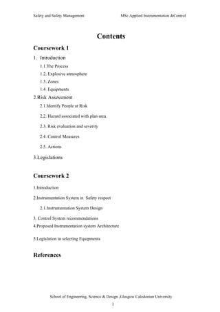
  • 16. Safety and Safety Management MSc Applied Instrumentation &Control Temperatur Earthing e meter Temperature Load cells meter T1 P4 Earthing Pressure meter T2 P1 Earthing P2 Mass Flow Meter1 F1 Air Figure 1: Proposed measurement system Firstly for tempreture,mass flow and pressure measurements we need to identify the areas of the plant where these measurements are required. Since the air cylinder has compressed gas hence excessive pressure may cause to leakage of air and become the source of oxidant.Also the gas line should be monitor for pressure so that it must not increase the maximum pressure limit of gas pipe .Hence pressure should be monitor for air cylinder continuously. To measure the pressure at cylinder outlet we are using pressure meter P1 as shown in figure 1.Also the outlet of nozzle bank connected to the pipeline should also be monitor for pressure using P2 pressure meters as shown in figure 1.P2 is used for measuring pressure for transferring the powder to receiving vessel. The pressure at P2 should not increase to 15 barg; School of Engineering, Science & Design ,Glasgow Caledonian University 16
  • 17. Safety and Safety Management MSc Applied Instrumentation &Control which is 1.5 times the MEP of powder which is 10 barg because the dust pipeline maximum explosion pressure is 1.5 to 2 times the MEP of powder. If it will increase above to this limit then an alarm will be switch on and if it becomes equal to 2 times than the air supply will be closed.As we know that to transfer powder to the receiving vessel we need certain pressure of air below which the powder does not transfer to the receiving vessel. Also required pressure would be different for different size of powder particles for example thick particles need more pressure to transfer from blow tank to receiving vessel. P4 meter can be used to monitor the pressure of pipeline contains dust as shown in figure 1. The temperature of air must also be monitor to make sure that its temperature must not increase maximum temperature limits and become the ignition source for the powder.T2 can be used to monitor temperature for air as shown in figure 1. To control the fire and explosion inside the pipeline it is required to continuously measure the temperature of mixture of air and powder inside the pipeline otherwise it will provide the ignition source for the powder and may become explode for example smouldering may produce frictional heat and can provide ignition source or collision of particles at the bends may cause to rise the temperature and become ignition source.So to monitor and control the temperature of pipeline we proposed T1 meter and transmitter which will continuously monitor the temperature and feedback the signal to the controller which switch on alarm when the temperature will be near to its limits and shutoff the air supply if system will deviate to these limits. There are two mass flow measurements are required.Firstly for mass flow measurement of air supply to the powder transferring pipeline F1 as shown in figure1 as it will measure the amount of air required to transfer powder from nozzle bank to the receiving vessel for example if we want to measure amount of air for 1 Kg of Pharmex we can do it by increasing the pressure from nozzle bank and measure the flow at which the powder will transfer to the receiving vessel. Also to measure the average mass flow of powder to the receiving vessel load cells are used as shown in figure 1. Moreover a PLC based system is proposed for complete automation of plant. School of Engineering, Science & Design ,Glasgow Caledonian University 17
  • 18. Safety and Safety Management MSc Applied Instrumentation &Control 2.1.Instrumentation System Design: Due to the high demand and advantages of digital transmission over analog transmission an instrumentation system using Profibus is proposed.Therefore all the devices i.e., sensors and transmitters using in the instrumentation system are Profibus based.Also only those devices have beed selected which are satisfying the ATEX certification for the required Zones and given material.Since we are dealing with Zone 20 in the plant hence we have onle used equipment 1 category devices for example in air measurements ATEX II 1 G devices are used and in dust measurement ATEX II 1 D devices are used in the given application. Below is the selection of some sensors and transmitters for instrumentation & measurements.Moreover some recommendations are proposed to replace the manual control by automatic control. 1. Pressure measurement The use of Endress+Hauser Cerabar S, PMP75 (endress.com) with metal sensor and Profibus PA protocol is proposed . These are high performance pressure sensors for extremely accurate and reliable measurements for gases and fluids with turndown ratio up to 100:1 and measuring range from 100mbar to 700 mbar.The selected sensor is ATEX certified from equipment 1 to equipment 3 category for gases or dust. As the plant operated in zone 20 hence we have selected ATEX II 1 G for air pressure measurement (P1,P2 and P3) and ATEX II 1 D for the dust (P4) . Figure 2: Cerabar S, PMP75 Pressure Transmitter ATEX II 1 GD School of Engineering, Science & Design ,Glasgow Caledonian University 18
  • 19. Safety and Safety Management MSc Applied Instrumentation &Control 2. Temperature sensor [5] We are required to measure temperature at the mixture of air and powder pipeline which is in zone 20.Hence we are required temperature transmitter with certification of ATEX II 1 D.For the given application we propose the Field mounted Temperature Transmitter ABB TF212-Ex (abb.com) with Profibus PA output.Input ranges from RTD,Thermocouples ,resistance and voltages. Field transmitters are applied where the highest demands are made on safety, robust ness and comfort .It is available in ATEX II 1/2 G/D for flame proof and dust explosion proof with intrinsically and non intrinsically safe type. It has extended long term stability and linear output signal with extended self diagnostics having 1 or two input channels. This dual-sensor input capability allows the transmitter to accept simultaneous input from two independent sensors. This dual-sensor configuration can be used for measuring differential temperatures, averaging temperature or redundant temperature measurement. Figure 3:ABB TF212-Ex Temperature transmitter ATEX II 1 D School of Engineering, Science & Design ,Glasgow Caledonian University 19
  • 20. Safety and Safety Management MSc Applied Instrumentation &Control 3. Air Mass Flow measurement The coriolis meter is preferred for mass flow measurements in Zones 0,1,20,21 according to ATEX [3]. If a moving mass is subjected to an oscillation perpendicular to its direction of movement, Coriolis forces occur depending on the mass flow. A Coriolis mass flowmeter has oscillating measuring tubes to precisely achieve this effect. The sensing element is a vibrating tube, through which the fluid flows. Figure 4:Coriolis Flow Measuring Principle The use of Endress + Hauser Promass 80 F (endress.com) universal mass flow transmitter having Profibus output is proposed.The selected sensor is ATEX certified for all zones and for gases and dust as well.Since we are measuring the mass flow of air in zone 20 hence we have selected EX II 1 G for the given application respectively in the places of F1 in the figure 1. Some characteristics for the transmitter are • The direct mass measurement • Is independent of conductivity, density, pressure or temperature of the fluid. • High accuracy for liquids and gases • No moving parts School of Engineering, Science & Design ,Glasgow Caledonian University 20
  • 21. Safety and Safety Management MSc Applied Instrumentation &Control Figure 5: Mass Flow meter ATEX II 1 GD Measuring Mass Flow rate of Powder: In order to measure mass flow rate of powder from blow tank to receiving vessel we used two load cells measuring weight of powder. It works by measuring the weight of powder and sends the signal to the PLC which measures the avarage mass flow rate by dividing the weight of powder by unit time in the control program and taking average. The Load cell can be equipment 3 because the load cell are attached to outside the receiving vessel as shown in the figure below and the zone outside the plant is 22. Load Cell Load Cell 2 Figure:Load Cells for measuring Mass flow rate Load cells should be calibrated and Atex certified. School of Engineering, Science & Design ,Glasgow Caledonian University 21
  • 22. Safety and Safety Management MSc Applied Instrumentation &Control Measuring Temperature of Gas: To make sure that the air going to the blow tank from compressor is not hot we can use a temperature transmitter of equipment 3 category as the air supplying part is in zone 22. 3. Control system Recommendations: 3.1.Automatic control of powder mass flow rate through Nozzle bank : It is proposed to replace the manual control of air pressure through nozzle bank by feedback control system.It can be achieved by replacing manual valve with analog solenoid valve control by the PLC. It works as follows -taking the user defined input of mass flow rate between minimum and maximum limit from the input panel -Taking feedback signal of mass flow rate of powder through load cells. -and then finally setting the solenoid valves until the desired mass flow rate will not achieved. For automatic control of nozzle bank we require Equipment 3 category of solenoid valves as we are in zone 22 in nozzle bank side i.e.,ATEX II 3 G . 3.2.Controlling compressor air supply : To control compressor air pressure it is proposed to use analog solenoid valve.It works as follows: -it takes signal from PLC. -The feedback signal can be blow tank pressue,pipeline pressure. The valve should be category 3 if the compressor is in the same room or could be any if in the separate room. 3.3.Automatic filling of powder in the blow tank: It is recommended to use automatic filling of powder in the blow tank. To achieve this a level sensor can be used to monitor level of powder inside blow tank. School of Engineering, Science & Design ,Glasgow Caledonian University 22
  • 23. Safety and Safety Management MSc Applied Instrumentation &Control The level sensor must be of equipment 1 category since blow tank is in zone 20. The system works as follows: -If level of powder is less than the minimum level then firstly the PLC stops the compressor supply and waits until the powder stored in the tank starts filling up to defined level and the PLC runs the compressor supply again. The supply of powder to the blow tank can be control by using a digital solenoid valve of equipment 1 category as it may be in zone 20.A proximity sensor of equipment 22 category can be used to send the position signal of solenoid valve to detect fault of solenoid valve. 3.4.Controlling Powder level in receiving vessel: The level of powder inside the receiving vessel can be control by measuring the weight of powder inside the receiving vessel to make sure that the powder will not exceeds from the maximum level i.e if the receiving vessel continue to accept filling the powder then if the powder exceeds from the desired level it may be dangerous or cause faults in the plant. To monitor level the load cells are calibrated with the level and give signals to the PLC and the PLC stops the air supply if the level will become to the maximum value by give stop signal to compressor outlet and shutoff compressor. 3.5.Programmable logic controller (PLC) : The heart of this control system is the PLC which receives signal from plant and sends control signals to the plant to control the plant.The PLC should be away from plant or if possible should be in other room.If in the same room as in which the plant is then the PLC should be places inside the cover to safe it from explosion. 3.6.Graphical User Interface (GUI): It is proposed to use the computer for graphical user interface .The Pc would be connected to the PLC and gather data from PLC.A GUI would be used to display data and alarm signals. School of Engineering, Science & Design ,Glasgow Caledonian University 23
  • 24. Safety and Safety Management MSc Applied Instrumentation &Control The computer should be either in the room other than plant or if in the same workplace then computer should be place inside the cover so that it will resist itself in case of the explosion. 3.7.Redundant system: In case of power failure a backup system is provided to power up the PLC and the computer. In case of PLC failure the plant must shut down. 3.8.Smoke & Fire Detectors: It is recommended to use fire and smoke detectors inside the room of category 3 in zone 22. An emergency shutdown system should be provided in case of fire and explosion. 4. Proposed Instrumentation System Architecture: It is recommended to use programmable logic controllers (PLC) based process control system for controlling the given pneumatic coveying system.Moreover it is proposed to use higher commuinication network like Ethernet or TP/IP for network access or even WEB.The block diagram of the implemented system may be as follows. School of Engineering, Science & Design ,Glasgow Caledonian University 24
  • 25. Safety and Safety Management MSc Applied Instrumentation &Control Figure 6:Proposed Instrumentation system Architecture 5. Legislations in selecting the Equipments: Equipment and devices are selected in agreement with regulation 7 of DSEAR [1] and ATEX as explained in the coursework 1. 5.1. Equipment Groups and categories [7] : There are two equipment groups defined in the EPS Regulations. Equipment Group I is equipment intended for use in underground parts of mines, and to those parts of surface installations of mines, liable to be endangered by firedamp and/or combustible dust. Equipment Group II is equipment intended for use in places, other than those specified for Equipment Group I, liable to be endangered by explosive atmospheres. Under ATEX 95 equipment is categorised as below: Mining equipment – School of Engineering, Science & Design ,Glasgow Caledonian University 25
  • 26. Safety and Safety Management MSc Applied Instrumentation &Control • Group I, Category M1 – very high level of protection, equipment may continue to operate in the presence of explosive atmosphere • Group I, Category M2 – high level of protection, equipment to be de-energised in presence of explosive atmosphere. Non-mining equipment - • Group II, Category 1 – equipment suitable for Zones 0, 20 • Group II, Category 2 – equipment suitable for Zones 1, 21 • Group II, Category 3 – equipment suitable for Zones 2, 22 REFERENCES [1] http://www.hse.gov.uk/fireandexplosion/dsear.htm [2] http://europa.eu.int/comm/enterprise/atex/guide/guidesec_en.pdf [3] http://www.hse.gov.uk/fireandexplosion/atex.htm [4] http://www.endress.com/corporate [5] http://www.abb.com/product/seitp330/c1256ccb004e516cc1256ab0004422dd.aspx [6] http://www.infoscotland.com/firelaw/files/RA_5.pdf [7] http://www.hse.gov.uk/electricity/atex/definitions.htm School of Engineering, Science & Design ,Glasgow Caledonian University 26