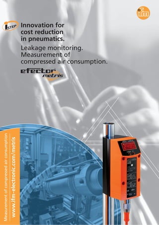
1. Innovation for
cost reduction
in pneumatics.
Leakage monitoring.
Measurement of
compressed air consumption.
Measurementofcompressedairconsumption
www.ifm-electronic.com/metris
R
2. MODE/ENTER SET
Decentralised monitoring, measurement
and display of compressed air consumption.
Many sources,
including the cam-
paign ”efficient
compressed air“*
clearly indicate the
growing interest
in the optimised
use of the energy
carrier compressed
air. This is a sub-
stantial saving
potential for
operating costs.
efector metris
helps to explore
this potential.
Measurement of
compressed air consumption
Optimised consumption
of compressed air
Allocation
of consumed quantities
The integral
4-digit LED display
plus the status
LEDs allow infor-
mation to be avail-
able at the point
of monitoring.
Whether peak
consumption,
present or accu-
mulated consump-
tion: Set switch or
alarm levels can be
accessed and
programmed via
pushbutton.
All settings can be
protected using
the electronic lock
function.
8 Nm3/h
12 Nm3/h
5.5 Nm3/h
* See
www.druckluft-effizient.de
3. 480
6,096
16,176
63,360
144
1,488
3,984
15,840
1.0
12.7
33.7
132.0
0.3
3.1
8.3
33.0
1.8
20.8
58.5
235.2
1.2
11.1
30.9
123.8
1
3
5
10
Hole Ø
[mm]
Air
loss
at
6 bar
[l/s]
Air
loss
at
12 bar
[l/s]
Energy
loss
kWh
at
6 bar
Energy
loss
kWh
at
12 bar
Cost
at
6 bar
[EUR]
Cost
at
12 bar
[EUR]
The installation
of several measur-
ing points in the
compressed air
system clearly
shows where and
how much com-
pressed air is con-
sumed. Thus the
consumption can
be allocated to
production
processes or prod-
ucts for optimising
cost structure.
Decentralised
location of efector
metris in the sup-
ply pipe to the
individual
machine unit.
Location of
efector metris in
the supply pipe
prior to distribu-
tion to several
installations or
machine units.
Leakage monitoring
Two reliable indications of air leakage
are the increase in consumption of com-
pressed air with unchanged machine
load and the continuing consumption
of compressed air when the machine is
no longer in operation.
Leakage at a glance.
The compressed air meter´s integrated
pipe length ensures easy mounting
and high measurement accuracy.
Easy to mount
in the supply system.
R
Annual energy costs due to leakage:
kWh x 0.06 EUR x 8000 operating hours/a.;
Source: www.druckluft-effizient.de
4. MODE/ENTER SET
From now on: Accurate monitor-
ing of compressed air consump-
tion with efector metris.
The low purchase price makes it
possible: To measure compressed
air where it is used.
Even very small leaks are detect-
ed and can be repaired in good
time.
The quantities consumed can be
directly allocated to the relevant
production units.
In situ display of total or current
consumption.
Switching, pulse or analogue
outputs for further external
processing.
Determine maintenance intervals
depending on consumption.
Measurement free from pressure
loss due to a special design of
the measuring probes.
Response time in the millisecond
range.
Calorimetric
measuring principle
Integrated
display for
direct
indication of
consumption.
Even small leaks
can cause unneces-
sary electricity
costs of several
thousand Euro
per year.
The calorimetric
principle measures
the standard
volume flow
irrespective of
temperature and
pressure – quickly
and over a wide
measuring range.
Leakage detection, energy cost
reduction and environmental protection.
5. *SP = switch point, **ASP = analogue start point, ***AEP = analogue end point
Application
Electrical design
Connection
Compressed air in industrial use
DC PNP
4-wire
Technical data efector metris
Output 1
Output 2 (programmable)
Operating voltage [V]
Current rating [mA]
Short-circuit protection, pulsed
Reverse polarity/overload prot.
Analogue output
Pressure resistance [bar]
Medium temperature [°C]
Power on delay time
Response time [s]
Measuring error in the
measuring range
Repeatability
Function display
Switching status
Display
Connection
19...30 DC
2 x 250
•
•
4...20 mA (max. 500 Ω)
16
0...60 (max. 90 % relative air humidity)
0.5 s
< 0.1
± (3 % measured value + 0.3 % final value of the measuring range)
± 1 % of the measured value
2 x yellow
4-digit alphanumeric display
Operating temperature [°C] 0...60
Protection IP 65 III
Material housing PBT-GF20; PC; Makrolon; stainless steel (304S15); Viton
Material sensor stainless steel (304S15); ceramics; PEEK; polyester
M 12 connector
2 x NC/NO programmable or 1 x NC/NO programmable
and 1 x analogue 4...20 mA
or 1 x NC/NO programmable and 1 x pulse output (1 pulse = 1 l or 1 m3)
Measuring range
[Nl/min / Nm3 / h]
Setting range
SP* [Nl/min / Nm3 / h]
ASP** [Nl/min / Nm3 / h]
AEP*** [Nl/min / Nm3 / h]
Pipe connection
Order no.
Sockets
Description
Order
no.
2 m PUR, M 12 straight, without LED E10906
5 m PUR, M 12 straight, without LED E10907
76,8
45
LED
display
programming
buttons
R
90
300
16,1
21,3
M12x1
100
111,5
Example: SD6000
4...1,250 /
0.25...75
12.5...3,750 /
0.75...225
6...1,250 / 0.4...75
0...938 / 0...56.3
313...1,250 / 18.8...75
19...3,750 / 1.1...225
0...2,812 / 0...169
937...3,750 / 56...225
DN15 DN25
SD6000 SD8000
0.039...11.67 x 103 /
2.3...700
0.0...11.67 x 103 / 4...700
0.0...8.75 x 103 / 0...525
2.92...11.67x103/175...700
DN50
SD2000
22.2...8,000 /
1.3...400
30...6,670 / 2...400
0...5,130 / 0...307.5
1,710...6,670 / 102...400
DN40
SD9000
6. Over 70 locations worldwide –
at a glance at www.ifm-electronic.com
ifmarticleno.7511082·Wereservetherighttomaketechnicalalterationswithoutpriornotice.·PrintedinGermanyonnon-chlorinebleachedpaper.01/05
ifm electronic gmbh
Teichstraße 4
D-45127 Essen
Tel. 02 01 / 2 42 20
Fax 02 01 / 2 42 22 00
e-mail:
info@ifm-electronic.com
http://www.ifm-electronic.com
visit our website
Position sensors
Proximity switches
Actuator sensors
Photoelectric sensors
Photoelectric systems
Incremental and
absolute encoders
Evaluation systems
Power supplies
Fluid sensors
and diagnostic systems
Inductive sensors for valves
Level sensors
Flow sensors
Pressure sensors
Vacuum sensors
Temperature sensors
Diagnostic systems
Networking
and control
Industrial communication
AS-Interface
Control systems
ifm electronic –