C44091316
•
1 j'aime•252 vues

Electronics & Communication Engineering, Computational mathematics, Image processing, Civil Engineering, Structural Engineering, Environmental Engineering, VLSI Testing & Low Power VLSI Design etc.

Recommandé
Recommandé
Contenu connexe
Tendances
Tendances (20)
En vedette
En vedette (20)
Similaire à C44091316
Similaire à C44091316 (20)
Dernier
Dernier (20)
C44091316
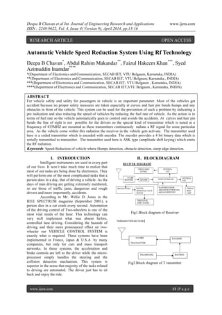
- 1. Deepa B Chavan et al Int. Journal of Engineering Research and Applications www.ijera.com ISSN : 2248-9622, Vol. 4, Issue 4( Version 9), April 2014, pp.13-16 www.ijera.com 13 | P a g e Automatic Vehicle Speed Reduction System Using Rf Technology Deepa B Chavan* , Abdul Rahim Makandar** , Faizul Hakeem Khan*** , Syed Azimuddin Inamdar**** *(Department of Electronics and Communication, SECAB IET, VTU Belgaum, Karnataka, INDIA) **(Department of Electronics and Communication, SECAB IET, VTU Belgaum, Karnataka , INDIA) ***(Department of Electronics and Communication, SECAB IET, VTU Belgaum , Karnataka, INDIA) ****(Department of Electronics and Communication, SECAB IET,VTU Belgaum , Karnataka, INDIA) ABSTRACT For vehicle safety and safety for passengers in vehicle is an important parameter. Most of the vehicles get accident because no proper safety measures are taken especially at curves and hair pin bends humps and any obstacles in front of the vehicle. This system can be used for the prevention of such a problem by indicating a pre indication and also reducing the speed of vehicles by reducing the fuel rate of vehicle. As the action is in terms of fuel rate so the vehicle automatically goes to control and avoids the accidents. At curves and hair pin bends the line of sight is not possible for the drivers so the special kind of transmitter which is tuned at a frequency of 433MHZ are mounted as these transmitters continuously radiate a RF signal for some particular area. As the vehicle come within this radiation the receiver in the vehicle gets activate. The transmitter used here is a coded transmitter which is encoded with encoder. The encoder provides a 4 bit binary data which is serially transmitted to transmitter. The transmitter used here is ASK type (amplitude shift keying) which emits the RF radiation. Keywords: Speed Reduction of vehicle where Humps detection, obstacle detection, steep edge detection. I. INTRODUCTION Intelligent instruments are used in every part of our lives. It won’t take much time to realize that most of our tasks are being done by electronics. They will perform one of the most complicated tasks that a person does in a day, that of driving a vehicle. As the days of man driving are getting extremely numbered, so are those of traffic jams, dangerous and rough drivers and more importantly, accidents. According to Mr. Willie D. Jones in the IEEE SPECTRUM magazine (September 2001), a person dies in a car crash every second. Automation of the driving control of Two-wheelers is one of the most vital needs of the hour. This technology can very well implement what was absent before, controlled lane driving. Considering the hazards of driving and their more pronounced effect on two- wheeler our VEHICLE CONTROL SYSTEM is exactly what is required. These systems have been implemented in France, Japan & U.S.A. by many companies, but only for cars and mass transport networks. In those systems, the acceleration and brake controls are left to the driver while the micro- processor simply handles the steering and the collision detection mechanism. This system is superior in the sense that majority of the tasks related to driving are automated. The driver just has to sit back and enjoy the ride. II. BLOCKDIAGRAM Fig1.Block diagram of Receiver Fig2.Block diagram of T ransmitter RESEARCH ARTICLE OPEN ACCESS
- 2. Deepa B Chavan et al Int. Journal of Engineering Research and Applications www.ijera.com ISSN : 2248-9622, Vol. 4, Issue 4( Version 9), April 2014, pp.13-16 www.ijera.com 14 | P a g e Fig3.Block diagram of Buzzer Section III. SYSTEM WORKING The arrangement at vehicle side is shown above a 433MHZ receiver which receives the RF signal when the transmitter frequency is interacting. The data available from receiver is in terms of serial this data has to be converted back in terms of parallel through a decoder which decodes the data and it is in the form of parallel. The decoded data is interfaced to microcontroller and the controller is so programmed that it now driving system drives the signal to a suitable level that which controls the action of electromechanical valve or pump. The valve regulates the fuel rate when the RF frequency is interacting with receiver. The fuel rate goes to low level which reduces the speed of vehicle so the accidents can avoided. For different curves the data differently encoded which is received by the RX and fuel rate can be adjusted differently. The same kind of method is implemented for the detection of humps and any obstacle on the roads with the help of IR LED and photo diode technique which acts as a proximity sensor when the IR signals transmitted from LED depending upon the distance of the obstacle or humps there is reflection of IR beam from that, material the circuit provides the signal to the microcontroller and with the same process of fuel reduction technique the vehicle fuel has been reduce and reduce the speed of the vehicle and prevents the accidents. The vehicle can be further avoided with accidents by alerting driver when the driver feels drowsiness during long driving or night driving. A three dimensional IR led and photo diode are arranged so that whenever an abstraction takes place between triggers the photodiode which generate a buzzer sound to alert the vehicle driver. The road steep edge detection can be done with the help of IR LED and photo diode technique, photo diode will be placed in the vehicle and IR led’s at the edge of the roads. If the edge is steep then link goes between IR led and photodiode which generate a buzzer sound to alert the vehicle driver. We are using here the solar panels which generate a electrical energy from natural resources like solar light. The energy generated from solar panel cannot be used directly, the energy has to be stored in the battery then it can be used as per our requirement. The solar panel is connected to the charge control unit in which the o/p DC voltage is flows in one direction for the purpose of charging the battery. It is also possible that the required amount of the voltage can be detected through this circuit and connects to the battery. The battery used here is either a lead acid type or maintenance free sealed lead acid battery or even a tubular battery can also be possible to use. The horn of the vehicle can be controlled through the controller action the microcontroller is so programmed that when at certain places or locations the horn is restricted the o/p of controller disable the horn and stops its working to prevents unnecessary noise generation near hospitals and school zones. When the vehicle passes from schools, hospitals etc controlling the vehicle horn are done. Within certain area across the schools, hospitals the transmitter will be keep, if the vehicle passes from that area the receiver kept in the vehicle receives the signal from that transmitter and that signal is fed to the controller and with the help of switching circuit the horn of the vehicle is controlled. Headlights of the vehicle are controlled with the help of LDR (light dependent resistor). When the head lights focus of the vehicle coming in front is more, then the LDR sensor in the vehicle senses that signal and the light beam of headlight goes low. As soon as that vehicle passes, the light beam of headlight goes high. IV. COMPONETS 4.1 RF Module (Radio Frequency): Radio Frequency, any frequency within the electromagnetic spectrum associated with radio wave propagation. When an RF current is supplied to an antenna, an electromagnetic field is created that then is able to propagate through space. Many wireless technologies are based on RF field propagation. Radio Frequency 10 KHz to 300 GHz frequency range that can be used for wireless communication Radio Frequency. Also used generally to refer to the radio signal generated by the system transmitter, or to energy present from other sources that may be picked up by a wireless receiver. There is various application of RF • Wireless mouse, keyboard. • Wireless data communication. • Alarm and security systems. • Home Automation, Remote control. • Automotive Telemetry. • Intelligent sports equipment. • Handheld terminals, Data loggers. • Industrial telemetry and tele-communications. • In-building environmental monitoring and control. • High-end security and fire alarms.
- 3. Deepa B Chavan et al Int. Journal of Engineering Research and Applications www.ijera.com ISSN : 2248-9622, Vol. 4, Issue 4( Version 9), April 2014, pp.13-16 www.ijera.com 15 | P a g e 4.2 RF Transmitter The TWS-434 extremely small, and are excellent for applications requiring short-range RF remote controls. The transmitter module is only 1/3 the size of a standard postage stamp, and can easily be placed inside a small plastic enclosure.TWS-434: The transmitter output is up to 8mW at 433.92MHz with a range of Approximately 400 foot (open area) outdoors. Indoors, the range is approximately 200 foot, and will go through most walls. The TWS-434 transmitter accepts both linear and digital inputs can operate from 1.5 to 12 Volts-DC, and makes building a miniature hand-held RF transmitter very Easy. The TWS-434 is approximately 1/3 the size of a standard postage stamp. 4.3 RF Receiver The receiver also operates at 433.92MHz, and has a sensitivity of 3uV. The RWS-434 receiver operates from 4.5 to 5.5 volts-DC, and has both linear and digital outputs. 4.4 RF Antenna The WC418 is made of 26 gauge carbon steel music wire that can be soldered to a PC board. This antenna has a plastic coated tip for safety and is 6.8 inches long, allowing.1 inch for insertion in a terminal or PC board. The following should help in achieving optimum antenna performance: • Proximity to objects such a users hand or body, or metal objects will cause an antenna to detune. For this reason the antenna shaft and tip should be positioned as far away from such objects as possible. • Optimum performance will be obtained from a 1/4 or 1/2 wave straight whip Mounted at a right angle to the ground plane. A 1/4 wave antenna for 418 MHz is 6.7 inches long. • In many antenna designs, particularly 1/4 wave whips, the ground plane acts as a counterpoise, forming in essence, a 1/2 wave dipole. Adequate ground plane area will give maximum performance. As a general rule the ground plane to be used as counterpoise should have a surface area equal to or greater than the overall length of the 1/4 wave radiating element (2.6 X 2.6 inches for a 6.7 inch long antenna).• Remove the antenna as far as possible from potential interference sources. Place adequate ground plane under all potential sources of noise. 4.5 MICROCONTROLLER The 89C51 is an 8-bit flash Microcontroller. It has 4 I/O ports and all ports are general I/O Ports. The port 3 is a serial port for connecting any serial devices and it is also used for interrupts. The fan out (output current) of the microcontroller is 10mA and if the connecting I/O devices require the current which is more than 10mA this may create overload to the microcontroller and can damage the microcontroller. So to avoid this, a buffer HCT245 is connected to the every ports of the microcontroller. The HCT245 is an 8-bit bi-directional buffer and is connected to the 8 pins of the ports. The pin 1 is enable pin connected to the Vcc through resistor. The pin 9 is the RESET pin of the microcontroller and is connected to the switch. Whenever a high pulse is applied to the RESET pin, the microcontroller jump to the address location 0000H and commence running from there. The capacitor connected to the RESET pin is charges and discharges through the Vcc which auto resets the microcontroller. Buffers also provide isolation between microcontroller and I/O devices which helps the microcontroller to operate in normal mode and the chances of program corruption can be avoided. The total power supply required the circuit is 5V and depending on the sensors, relays, motors the current consumption has been decided. If the I/O requirement is more than the fan out of buffer a transistorized relay switching need to connect. 4.6 Software requirement Keil Software is the leading vendor for 8/16- bit development tools (ranked at first Position in the 2004 Embedded Market Study of the Embedded Systems and EE Times Magazine). Keil Software is represented world-wide in more than 40 countries. Since the market introduction in 1988, the Keil C51 Compiler is the de facto industry standard and Supports more than 500 current 8051 device variants. Now, Keil Software offers development tools for ARM. Keil Software makes C compilers, macro assemblers, real-time kernels, debuggers, Simulators, integrated environments, and evaluation boards for the 8051, 251, ARM, and XC16x/C16x/ST10 microcontroller families. Keil Software is pleased to announce simulation support for the Atmel AT91 ARM family of microcontrollers. The Keil μVision Debugger simulates the complete ARM instruction- set as well as the on-chip peripherals for each device in the AT91 ARM/Thumb microcontroller family. The integrated simulator provides complete peripheral simulation. Other new features in the μVision Debugger include: An integrated Software Logic Analyzer that measures I/O signals as well as program Variables and helps developers create complex signal processing algorithms. An Execution Profiler that measures time spent in each function, source line, and Assembler instruction. Now developers can find exactly where programs spend the most Time."Using nothing more than the provided simulation support and debug scripts, developers can create a high-fidelity simulation of
- 4. Deepa B Chavan et al Int. Journal of Engineering Research and Applications www.ijera.com ISSN : 2248-9622, Vol. 4, Issue 4( Version 9), April 2014, pp.13-16 www.ijera.com 16 | P a g e their actual target hardware and environment. No extra Hardware or test equipment is required. The Logic Analyzer and Execution Profiler will help Developers when it comes time to develop and tune signaling algorithms." said Jon Ward, President of Keil Software USA, Inc. V. INTERNAL CIRCUITARY Fig4. Internal Circuitary VI. APPLICATIONS AND ADVANTAGES 1) Speed control through RF technique. 2) Speed control at humps. 3) Speed controls when any obstacle found. 4) U curves safety indications. 5) Low power transmitter is enough for operation. 6) Lot of accidents possible is avoided. 7) Suitable for all kinds of vehicle safety system. 8) Less man power is required 9) Steep edges are detected. 10) Driver alertness will be more. 11) High, low beam of headlights are controlled automatically. 12) Controlling the horn of the vehicles across schools, hospitals etc. 13) Because of using solar it will be cost effective VII. FUTURE WORK At present, we have excluded geared two- wheelers from the scope of this project because it complicates the control mechanism. In future the work can be applied to geared two-wheelers. VIII. CONCLUSION A prototype model of controller is built on the speed mixing capability. Signals from The sign board of various zones (school zone, highway zone, “U” turn zone etc) is Intelligently treated individually & generates input signals for driving actuators – car engine and additional DC motor. They, in turn, jointly control the speed of vehicle wheels. This design successfully utilizes a new idea of hybrid vehicle recently immerged in automotive industry. The system does not require a physical braking subsystem which will reduce the overall cost of a car. REFERENCES [1] Telaprolu,m.k, sarma,V.V.; ratankanth, E.K.;Rao, S.N.; Banda,v., vehicular Electronics and safety (ICVES), IEEE international conference pune (2009). [2] Gangadhar, S.; R N shetty Inst. Of Technol, An Intelligent road traffic control system, IEEE conference publication kahargpur (2010). [3] Berndt, Don, Real-Time Embedded Technology and Applications Symposium (RTAS), IEEE Education & Learning (2005). [4] Kassem, N. Microsoft Corp., Redmond, WA, USAKosba, A.E.; Youssef, M.;VRF- Based Vehicle Detection and Speed Estimation vehicular Technology Conference (VTC Spring), IEEE (2012). [5] Murthy, C.; Manimaran, G.; Resource Management in Real-Time Systems and Networks2001. [6] Nishiyama, Y. ISUZU Advanced Engineering Center LTD., Kanagawa, JapanKondoh, A.; Hirado, A.; Akiyama, H. The system and the function of position regulated speed control device, Vehicle Navigation and Information Systems Conference, 1996. VNIS '96 [7] Ankita Mishra, Jyoti Solanki, Harshala Bakshi, Priyanka Saxena,Pranav Paranjpe: Design of RF based speed control system for Vehicles International Journal of Advanced Research in Computer and Communication Engineering Vol. 1, Issue 8, October 2012