MICRO-POWER METER
•
0 j'aime•406 vues

IJERA (International journal of Engineering Research and Applications) is International online, ... peer reviewed journal. For more detail or submit your article, please visit www.ijera.com

Recommandé
Contenu connexe
Tendances
Tendances (20)
En vedette
En vedette (20)
Similaire à MICRO-POWER METER
Similaire à MICRO-POWER METER (20)
Dernier
Dernier (20)
MICRO-POWER METER
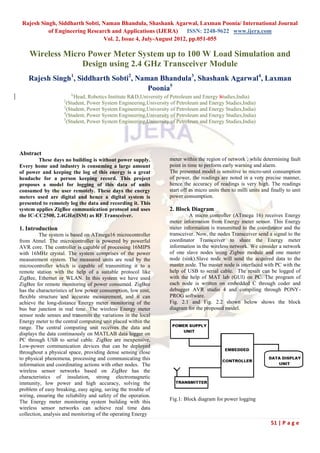
- 1. Rajesh Singh, Siddharth Sobti, Naman Bhandula, Shashank Agarwal, Laxman Poonia/ International Journal of Engineering Research and Applications (IJERA) ISSN: 2248-9622 www.ijera.com Vol. 2, Issue 4, July-August 2012, pp.051-055 Wireless Micro Power Meter System up to 100 W Load Simulation and Design using 2.4 GHz Transceiver Module Rajesh Singh1, Siddharth Sobti2, Naman Bhandula3, Shashank Agarwal4, Laxman Poonia5 1( Head, Robotics Institute R&D,University of Petroleum and Energy Studies,India) 2 (Student, Power System Engineering,University of Petroleum and Energy Studies,India) 3 (Student, Power System Engineering,University of Petroleum and Energy Studies,India) 4 (Student, Power System Engineering,University of Petroleum and Energy Studies,India) 5 (Student, Power System Engineering,University of Petroleum and Energy Studies,India) Abstract These days no building is without power supply. meter within the region of network , while determining fault Every home and industry is consuming a large amount point in time to perform early warning and alarm. of power and keeping the log of this energy is a great The presented model is sensitive to micro-unit consumption headache for a person keeping record. This project of power, the readings are noted in a very precise manner, proposes a model for logging of this data of units hence the accuracy of readings is very high. The readings consumed by the user remotely. These days the energy start off as micro units then to milli units and finally to unit meters used are digital and hence a digital system is power consumption. presented to remotely log the data and recording it. This system applies ZigBee communication protocol and uses 2. Block Diagram the IC-CC2500, 2.4GHz(ISM) as RF Transceiver. A micro controller (ATmega 16) receives Energy meter information from Energy meter sensor. This Energy 1. Introduction meter information is transmitted to the coordinator and the The system is based on ATmega16 microcontroller transceiver. Now, the nodes Transceiver send a signal to the from Atmel. The microcontroller is powered by powerful coordinator Transceiver to share the Energy meter AVR core. The controller is capable of processing 16MIPS information in the wireless network. We consider a network with 16MHz crystal. The system comprises of the power of one slave nodes using Zigbee module and one master measurement system. The measured units are read by the node (sink).Slave node will send the acquired data to the microcontroller which is capable of transmitting it to a master node. The master node is interfaced with PC with the remote station with the help of a suitable protocol like help of USB to serial cable. The result can be logged of ZigBee, Ethernet or WLAN. In this system we have used with the help of MAT lab (GUI) on PC. The program of ZigBee for remote monitoring of power consumed. ZigBee each node is written on embedded C through coder and has the characteristics of low power consumption, low cost, debugger AVR studio 4 and compiling through PONY- flexible structure and accurate measurement, and it can PROG software. achieve the long-distance Energy meter monitoring of the Fig. 2.1 and Fig. 2.2 shown below shows the block bus bar junction in real time. The wireless Energy meter diagram for the proposed model. sensor node senses and transmits the variations in the local Energy meter to the central computing unit placed within the range. The central computing unit receives the data and displays the data continuously on MATLAB data logger on PC through USB to serial cable. ZigBee are inexpensive, Low-power communication devices that can be deployed throughout a physical space, providing dense sensing close to physical phenomena, processing and communicating this information and coordinating actions with other nodes. The wireless sensor networks based on ZigBee has the characteristics of insulation, strong electromagnetic immunity, low power and high accuracy, solving the problem of easy breaking, easy aging, saving the trouble of wiring, ensuring the reliability and safety of the operation. Fig.1: Block diagram for power logging The Energy meter monitoring system building with this wireless sensor networks can achieve real time data collection, analysis and monitoring of the operating Energy 51 | P a g e
- 2. Rajesh Singh, Siddharth Sobti, Naman Bhandula, Shashank Agarwal, Laxman Poonia/ International Journal of Engineering Research and Applications (IJERA) ISSN: 2248-9622 www.ijera.com Vol. 2, Issue 4, July-August 2012, pp.051-055 interface. It has 32 programmable I/O lines and 40 pin PDIP. It is capable of executing one instruction per cycle. 3.2. MAX232 This is level converter IC from MAXIM which is used to make logic compatibility between TTL and RS232 logic. The IC converts the 5V logic into a 8V negative logic. This converter is located between the almega16 microcontroller and the zigbee module, the microcontroller uses TTL logic whereas the zigbee module uses RS logic. The main purpose of this converter is to convert the TTL logic to RS logic. 3.3. POWER SUPPLY UNIT This unit is basically designed to power up the node 1 and node 2. This provides 5 V, 500mA output to drive the nodes. Here, the AC voltage at 220V is stepped down to 20V using a 220/20V step down transformer. This AC voltage at 20V is fed to rectifier that converts it to DC voltage and is then filtered using 40 Farad shunt capacitor. The filtered DC Fig.2: Block diagram for central data logging system voltage is then regulated using a 7805 regulator, and is then supplied to the the microcontroller at 5V, 500 mA. 3. Hardware Development The power measuring unit measures the power from main line. This data is fed to microcontroller. 3.4. LCD Microcontroller fetches the data and transmits it over the network. The following is the list for the components used This is most widely used display device for embedded in the proposed model: systems. The LCD unit receives character codes (8 bits per ATmega16/32 character) from a microprocessor or microcomputer, latches MAX232 the codes to its display data RAM (80-byte DD RAM for Power supply units storing 80 characters), transforms each character code into a 5 ´ 7 dot-matrix character pattern, and displays the Data logging systems characters on its LCD screen. ZigBee modules LCD Display Fig.4 LCD 16x2 Fig.3: Power suppy interfacing with ATMEGA16 with LCD 3.1. Atmega16 It is a microcontroller from Atmel which is powered by the AVR core. It is an 8-bit,low powered microcontroller with 16 kilobytes in-system self programmable flash. This core is capable of running 16MIPS with a 16MHz crystal. It has an advanced RISC architecture with 32 X 8 general purpose working registers. The microcontroller features programmable serial USART and master/slave SPI serial 52 | P a g e
- 3. Rajesh Singh, Siddharth Sobti, Naman Bhandula, Shashank Agarwal, Laxman Poonia/ International Journal of Engineering Research and Applications (IJERA) ISSN: 2248-9622 www.ijera.com Vol. 2, Issue 4, July-August 2012, pp.051-055 Fig.7 Zigbee interfacing with DB9 Fig.5 LCD interfacing with ATMEGA16 3.5. ZigBee Modules This is the radio frequency transceiver module, which can facilitate the OEM designers to design their remote control applications in the quickest way. The circuit is designed with SMD components and the module size is small enough to be able to be fitted in almost any application. These modules are based on IC CC2500 by chipcom. It works at frequency of 2.4GHz, bandwidth of 250 kbps at LAN 802.15.4 protocol. The device works in half duplex mode. Zigbee modules are low power consuming devices, i.e. they can even work on battery power for long durations. These modules are one time expenditure devices, they do not require constant maintenance. These devices have no moving parts and are rugged in construction hence can tolerate rough usage. Fig.8 Simulation model of proposed model using Protesus trial version 4. Software Development The firmware for the model is developed using C programming language. The binary code is generated with the help of WinAVR compiler based on GCC port by GNU. The IDE used is AVR Studio. The data logging system may use any of software that is capable of logging data from a serial port. It may be a user created software or a standard software like HyperTerminal. Fig.6 Zigbee view Microcontroller has been programmed to test the hardware as well to achieve the goal of WSN application,which involved the following steps 53 | P a g e
- 4. Rajesh Singh, Siddharth Sobti, Naman Bhandula, Shashank Agarwal, Laxman Poonia/ International Journal of Engineering Research and Applications (IJERA) ISSN: 2248-9622 www.ijera.com Vol. 2, Issue 4, July-August 2012, pp.051-055 Fig.9 Steps for software development 4.1. Coding / Debugging Fig.10 AVR ISP programmer Coding / debugging in a high-level language (such as C, or 4.4. Evaluation Java) or assembler. A compiler for a high level language If the system performs all the required tasks and behaves as helps to reduce production time. To program the expected the software development phase is over. If not, the microcontrollers the WinAVR [2] was used. Although inline whole procedure will have to be repeated again. One of the assembly was possible, the programming was done strictly difficulties of programming microcontrollers is the limited in the C language. The source code has been commented to amount of resources the programmer has to deal with. In facilitate any occasional future improvement and PCs resources such as RAM and processing speed are maintenance. WinAVR is a suite of executable, open source basically limitless when compared to microcontrollers. In software development tools for the Atmel AVR series of contrast to a PC, the code on microcontrollers should be as RISC microprocessors hosted on the Windows platform. It low on resources as possible. includes the GNU GCC compiler for C and C++. WinAVR We have used our fully buffered, interrupt driven contains all the tools for developing on the AVR. This USART library for usart related job. The library comes in includes AVR-gcc (compiler), AVR-gdb (debugger) etc. two files. Test Source Code has been written in C Language to test the USART.c microcontroller. USART.h 4.2. Compiling Main_energymT.c The compilation of the C program converts it into machine Main_energymR.c language file (.hex). This is the only language the microcontroller will understand, because it contains the original program code converted into a hexadecimal format. During this step there were some warnings about eventual 5. Set up of the system errors in the program. 4.3. Burning Machine language (hex) file of compile program burned into the microcontroller’s program memory is achieved with a dedicated programmer, which attaches to a PC’s peripheral. PC’s serial port has been used for the purpose. In the present work the Ponyprog programmer has been used to burn the machine language file into the microcontroller’s program memory. Ponyprog is serial device programmer software with a user-friendly GUI framework available for Windows95/98/ME/NT/2000/XP and Intel Linux. Its purpose is reading and writing every serial device. It supports I²C Bus, Micro wire, SPI eeprom, and the Atmel AVR and Microchip PIC microcontroller. The microcontrollers were programmed in approximately two seconds with a high speed-programming mode. The program memory, which is of Flash type, has, just like the EEPROM, a limited lifespan. On the AVR microcontroller family it may be reprogrammed up to a thousand times without any risk of data corruption. Fig.11 Master Node Atmega16Programmer (ISP) which is used to burn the The master node shown in Fig.11 consists of the program into AVR microcontrollers is shown in Fig. 10. transmiting end of the customized meter reading hardware which contains a 100w bulb, a power supply unit, the 54 | P a g e
- 5. Rajesh Singh, Siddharth Sobti, Naman Bhandula, Shashank Agarwal, Laxman Poonia/ International Journal of Engineering Research and Applications (IJERA) ISSN: 2248-9622 www.ijera.com Vol. 2, Issue 4, July-August 2012, pp.051-055 atmega16 controller, and the zigbee module as the main [4] Extreme Electronics: components. http://www.extremeelectronics.co.in [5] A.Flammini, D.Marioli, E.Sisinni, A.Taroni, A real- time wireless sensor Network for temperature monitoring, IEEE Transactions on Industrial Electronics 1-4244-0755-9/07 2007 [6] Das, V.V., Wireless communication system for energy meter reading , ACEEE, Trivandrum, India [7] Bharath, P.Ananth, N.Vijetha, S. Prakash, K.V.J., Wireless automated digital energy meter, JSS Acad. of Tech. Educ., Bangalore [8] Xiaofan Jiang, Dutta P. ,Culler D. , Stoica I, Micro Power Meter for Energy Monitoring of Wireless Sensor Networks at Scale, Univ. of California, Berkeley [9] Kistler R., Bieri M., Wettstein R., Klapproth A. , CEESAR, Tunneling Smart Energy protocols over ZigBee, iHomeLab, Lucerne Univ. of Appl. Sci. & Arts, Horw, Switzerland Fig.12 Slave Node The slave node shown in Fig.12 consists of receiving end of the customized meter reading hardware which contains the power supply unit, the atmega16 controller, the LCD display unit, and the zigbee module as its main components. 6. Future Scopes The information logged by the proposed system can be transmitted over the internet. It may be used there to log the data into the used account and online dispatching of the electricity bills. Unification of all metering devices to one central coordinating node can be achieved. In the future these metering devices can be used in many other fields such as gas metering, water usage in domestic and industrial use, companies can benefit from these close range metering devices and save costs and minimize errors in metering. 7. Conclusion This system, comparing with traditional manual inspection and large scale wiring, the accuracy of data acquisition and the real-time of transmission is improved significantly, and its construction is flexible, measurement is precise, operation is simple and energy is saved for entire monitoring system. The major savings are in the form of expenses to monitor every single metering device accompanied by savings in manual labour and negligible error in readings procured by personnel. It also eliminates the chances of manual error in meter reading. References [1] F.L.Lewis, Wireless Sensor Networks-Chapter 4, Smart environments:Technologies, Protocols, and Applications Journal. [2] Mike Horton and John Suh, A Vision for Wireless Sensor Networks, IEEE transactions on Industrial Electronics 0-7803-8846-1/05, 2005. [3] Atmel Documentation: http://www.atmel.com 55 | P a g e