International Journal of Engineering Research and Development (IJERD)
•
1 j'aime•408 vues

International Journal of Engineering Research and Development is an international premier peer reviewed open access engineering and technology journal promoting the discovery, innovation, advancement and dissemination of basic and transitional knowledge in engineering, technology and related disciplines.

Recommandé
Contenu connexe
Tendances
Tendances (20)
En vedette
En vedette (9)
Similaire à International Journal of Engineering Research and Development (IJERD)
Similaire à International Journal of Engineering Research and Development (IJERD) (20)
Plus de IJERD Editor
Plus de IJERD Editor (20)
Dernier
Dernier (20)
International Journal of Engineering Research and Development (IJERD)
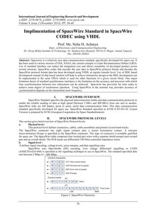
- 1. International Journal of Engineering Research and Development e-ISSN: 2278-067X, p-ISSN: 2278-800X, www.ijerd.com Volume 9, Issue 2 (November 2013), PP. 36-40 Implimentation of SpaceWire Standard in SpaceWire CODEC using VHDL Prof. Ms. Neha D. Acharya Dept., of Electronics and Communication Engineering, Dr. Jivraj Mehta Institute of Technology, Nr. Sankara Eye Hospital, NH No.8, Mogar, Anand, Gujarat, Pin: 388340–INDIA Abstract:- Spacewire is a relatively new data communication standard, specifically developed for space use. It has been used in various mission of ESA, NASA; the current example is Lunar Reconnaissance Orbiter (LRO). Use of standard interface can reduce the integration cost and allows reusability of developed product across several missions. SpaceWire codec that encodes the user data in SpaceWire protocol format and decodes the SpaceWire protocol format data has been developed using VHDL at register transfer level. Use of HDL based development instead of chip based solution will help to achieve miniaturize design as the HDL development can be implemented in the same FPGA which is used for other functions of a given circuit block. One major limitation factor of standard asynchronous interfaces is the limitation on the accuracy and precision with which time synchronization between two subsystems can be achieved. Spacewire has provision for time codes to achieve some degree of isochronous operation. Using SpaceWire in the nominal way provides accuracy of synchronization depends on the transmitted clock frequency. I. SPACEWIRE OVERVIEW SpaceWire Standard specifies the physical interconnection media and data communication protocols to enable the reliable sending of data at high speed (between 2 Mb/s and 400 Mb/s) from one unit to another. SpaceWire links are full duplex, point to point, serial data communication links. This data communication standard specifically developed for space use. SpaceWire Standard specified as ECSS E-ST-50-12C (Latest Version) is prepared by ECSS (European Cooperation for Space Standardization) II. SPACEWIRE PROTOCOL LEVELS This section gives brief overview of SpaceWire Protocol levels. a. Physical level : This protocol level defines connectors, cables, cable assemblies and printed circuit board tracks. The SpaceWire connector has eight signal contacts plus a screen termination contact. A nine-pin micro-miniature D-type is specified as the SpaceWire connector. This type of connector is available qualified for space use. The SpaceWire cable comprises four twisted pair wires with a separate shield around each twisted pair and an overall shield. The PCB tracks are differential 100 Ohm controlled impedance tracks b. Signal level : It defines signal encoding, voltage levels, noise margins, and data signalling rates. SpaceWire uses Data-Strobe (DS) encoding. Low voltage differential signalling or LVDS (ANSI/TIA/EIA-644) is specified as the signalling technique to use in SpaceWire. The standard specified data rate between 2 Mbps to > 400 Mbps Control characters P 1 0 0 FCT Flow control token P 1 0 1 EOP Normal end of packet P 1 1 0 EEP Error end of packet P 1 1 1 ESC Escape Control codes P 1 1 (P) 1 0 1 0 0 0 T0 T1 T2 T3 T4 T5 T6 T7 Time-Code NULL (P) P 1 1 1 1 LSB MSB Figure-1: SpaceWire Characters 36
- 2. Implimentation of SpaceWire Standard in SpaceWire CODEC using VHDL c. Character level : It defines the data and control characters used to manage the flow of data across a link. There are two types of characters and two control codes and are shown in Fig-1. The parity bit covers the previous eight bits of a data character or two bits of a control character, the current parity bit and the current datacontrol flag. It is set to produce odd parity so that the total number of 1’s in the field covered is an odd number. d. Exchange level : It defines the protocol for link initialization, flow control, link error detection and link error recovery. During initialization, NULL and FCTs are used for establishing the connection Initialization. Once the connection is established and host system is ready to receive data charters, it requests the link transmitter to send a flow control token (FCT). The FCT is received at the other end of the link enabling the transmitter at that end to send up to eight more N-Chars. Link disconnection is detected when following reception of a data bit no new data bit is received within a link disconnect timeout window (850 ns).Parity errors occurring within a data or control character are detected when the next character is sent, since the parity bit for a data or control character is contained in the next character. Packet level : Defines encapsulation of data information in packets, to be send over the link. The format of a packet is illustrated in Figure-2. e. Figure-2: Packet format The “destination address” is a list of zero or more data characters that represent the destination identity. The “cargo” is the data to transfer from source to destination. The “end of packet marker” is used to indicate the end of a packet. Two end of packet markers are defined a. EOP normal End of Packet marker - indicates end of packet; b. EEP error End of Packet marker - indicates that the packet is terminated prematurely due to a link error. Since there is no start of packet marker, the first data character following an end of packet marker (either EOP or EEP) is regarded as the start of the next packet. f. Network level : The network level defines what a SpaceWire network is, describes the components that make up, explains how packets are transferred across it, and details the manner in which it recovers from errors. III. SPACEWIRE CODEC DEVELOPMENT The Codec has been implemented using pipelining inbuilt so that maximum speed performance can be achieved. Single clock edge has been used in most of the places to achieve more timing margin. a. SpaceWire Link Interface: It is responsible for implementing signal, character and exchange and packet level of protocols. Both Single data Rate and Double Data Rate (DDR) options for transmitted data have been developed. For DDR option, target device (e.g. Xilinx, Actel FPGA) specific DDR module is to be used. Figure-3: Block Diagram of SpaceWire Codec b. Host data interface (Application Data Interface): It is responsible for handling the data transactions between SpW Link Interface and host application (typically a sensor output or mass memory or data handling system). The Host data interface is specific to a target device but has been written at RTL level and has been designed to suite the requirement of different target devices. c. Time Distribution Interface: It is responsible for distributing/ maintaining the basic time information specified in standard. d. FIFO: 37
- 3. Implimentation of SpaceWire Standard in SpaceWire CODEC using VHDL To smooth out the asynchronous transactions between host and SpW Link I/F and to implement the minimum receiver buffer space required by SpW standard . FIFO memory has been used for this purpose. The FIFOs are also target device specific. For devices which do not have FIFO, external FIFO can be used. IV. SPACEWIRE LINK INTERFACE Link Interface is the main functional block of Codec. The SpaceWire standard does not specify any specific implementation. One possible implementation of the SpW link interface has been given in the standard for illustration purpose. CLOCK TICK_IN TIME_IN CONTROL-FLAGS_IN TX CLOCK TX_WRITE TX_DATA/CONTROL-FLAG TX_READY Dout Sout TRANSMITTER RESET Enable_Tx Send_NULLs Send_FCTs Send_N-Chars Send_Time-Codes After 12,8 s After 6,4 s gotFCT got Time-Code STATE MACHINE gotN-Char gotNULL gotBit CreditError Rx_Err Enable_Rx CLOCK RESET LINK START LINK DISABLE AUTOSTART RESET Din Sin TIMER RECEIVER BUFFER_READY RX_DATA/CONTROL-FLAG BUFFER_WRITE CONTROL-FLAGS_OUT TIME_OUT TICK_OUT RX_CLOCK RX CLOCK RECOVERY Figure-4: Block diagram of SpaceWire Link The Transmitter is responsible for sending the use data (N-Char, EOP, EEP), Time-code, Flow Control Token (FCT) and NULL. Rx Clock recovery recovers the receiver clock from the data and strobe signals. Receiver decodes the received serial bit stream and provides the decoded information to State machine for link maintenance and to Receiver buffer (FIFO in our case).The state machine is responsible for link –initialization and handling the errors. The state machine is shown in figure-5. Figure-5: SpaceWire State Machine 38
- 4. Implimentation of SpaceWire Standard in SpaceWire CODEC using VHDL Timer is used to generate 12.8us and 6.4us time-outs for state machine and 850 ns timeout for disconnect detection. TX Clock generator block generates clock for the transmitter operation. V. IMPLEMENTATION ASPECTS The Codec Implemented at SEDA is aimed at using minimum number of clock resources as in FPGA as the numbers of clock resources are very low. The CODEC uses following two clocks a. Sys_clk It is system clock. It is multipurpose clock and used for following functions 1. State machine for link initialization 2. Transmitter clock generation The System clock can be set between any values from 10 MHz to 200 MHz. A Generic is used to define the clock division factor to derive 10 MHz initialization clock from system clock. The Codec has the provision to set 8 speed of transmitter clock. b. RX Clock It is clock recovered by “Rx Clock Recovery” circuit block of figure-4. The maximum receiver clock frequency that can be accepted by codec is less than the system clock frequency. VI. INTEROPERABILITY TEST The interoperability test is carried out with SpaceWire Codec from Star Dundee. During initial development phase Alter FPGA based hardware was used. Due to speed limitation caused by the devices on this board, Xilinx FPGA based hardware can develop. The star Dundee is spinout of University of Dundee that has developed SpaceWire Codec for ESA. The instruments from Star Dundee are the most authentic third part development tools available today. The practical performance can demonstrate using for Xilinx Vertex-2 Series FPGA. The document also contains the static timing analysis results for Actel AX series FPGA and prototype results with Altera FPGA based development system. Instruments required for the test results are, a. Spacewire Codec Simulator USB-Brick from Star-Dundee is used for this purpose. It is a routing switch connects together the two SpaceWire interfaces, USB 2.0 interface and a configuration port. Each Link Interface can be used as standalone Codec. The configuration port is used to control the operation of the SpaceWire-USB Brick, so it can be controlled from the USB 2.0 port or remotely via either SpaceWire interface. SpaceWire link speeds, pattern of data operating modes, etc, can be set through the configuration port and status and error information can be read through validation software. b. SpaceWire Link Analyzer The Link Analyser provides a rich set of test functionality in a single instrument specifically designed to support hardware and software engineers developing SpaceWire systems. It comprises a SpaceWire interface pod and software running on a host PC. The interface pod is connected to the host PC using a USB 2.0. cable. It has following facility 1. Link level trace: Monitoring, tracing and recording traffic at the link level. Used to confirm link startup, flow-control, data transfer, and error recovery. · 2. Packet level trace: Monitoring, tracing and recording of SpaceWire packets. Used to monitor the flow of packets across a SpaceWire link, the response of a system to packet errors, and the control of SpaceWire systems using control packets. 3. Fault injection: The SpaceWire Link Analyzer allows disconnect and parity to be injected in the monitored link. These faults can be used to validate the system level, operation in the event of various failures – an important issue for flight equipment. VII. a. SPACEWIRE CODEC SIMULATE RESULT ON MODELSIM WINDOW One end as TX and one end as RX (Both End at 200 Mbps) 39
- 5. Implimentation of SpaceWire Standard in SpaceWire CODEC using VHDL VIII. FUTURE SCOPES The SpaceWire CODEC IP can be used as a standalone module or connected to our SpaceWire Switch Core to form a complete SpaceWire Routing Switch (Router). Router switches connecting several links that routes packets from one link to another in SpaceWire network for space application. SpaceWire network is use for onboard spacecraft, its nodes like Sensors, Memory units, Processing subsystems, Down-link telemetry subsystem, etc, IX. [1]. [2]. [3]. [4]. [5]. [6]. REFERENCES ECSS E-ST-50-12C (Latest Version)- SpaceWire: Links, nodes, routers and networks – by ECSS, 31July2008 SpaceWire Codec VHDL User Manual - by University of Dundee Spacewire: STAR-Dundee Product Overview - by University of Dundee www.aeroflex.com/spacewire “SpaceWire Homepage,” www.estec.esa.nl/tech/spacewire/standards www.ccsds.org 40