Network switches, functions & role in networks
•Télécharger en tant que DOCX, PDF•
5 j'aime•22,602 vues

Network switches, functions & role in networks

Recommandé
Contenu connexe
Tendances
Tendances (20)
En vedette
En vedette (20)
Similaire à Network switches, functions & role in networks
Similaire à Network switches, functions & role in networks (20)
Plus de IT Tech
Plus de IT Tech (20)
Dernier
Dernier (20)
Network switches, functions & role in networks
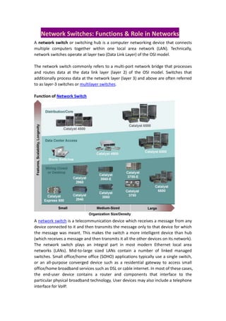
- 1. Network Switches: Functions & Role in Networks A network switch or switching hub is a computer networking device that connects multiple computers together within one local area network (LAN). Technically, network switches operate at layer two (Data Link Layer) of the OSI model. The network switch commonly refers to a multi-port network bridge that processes and routes data at the data link layer (layer 2) of the OSI model. Switches that additionally process data at the network layer (layer 3) and above are often referred to as layer-3 switches or multilayer switches. Function of Network Switch A network switch is a telecommunication device which receives a message from any device connected to it and then transmits the message only to that device for which the message was meant. This makes the switch a more intelligent device than hub (which receives a message and then transmits it all the other devices on its network). The network switch plays an integral part in most modern Ethernet local area networks (LANs). Mid-to-large sized LANs contain a number of linked managed switches. Small office/home office (SOHO) applications typically use a single switch, or an all-purpose converged device such as a residential gateway to access small office/home broadband services such as DSL or cable internet. In most of these cases, the end-user device contains a router and components that interface to the particular physical broadband technology. User devices may also include a telephone interface for VoIP.
- 2. An Ethernet switch operates at the data link layer of the OSI model to create a separate collision domain for each switch port. With 4 computers (e.g., A, B, C, and D) on 4 switch ports, A and B can transfer data back and forth, while C and D also do so simultaneously, and the two conversations will not interfere with one another. In the case of a hub, they would all share the bandwidth and run in half duplex, resulting in collisions, which would then necessitate retransmissions. Using a switch is called microsegmentation. This allows computers to have dedicated bandwidth on a point-to-point connection to the network and to therefore run in full duplex without collisions. Role of Switches in Networks Switches may operate at one or more layers of the OSI model, including data link and network. A device that operates simultaneously at more than one of these layers is known as a multilayer switch. In switches intended for commercial use, built-in or modular interfaces make it possible to connect different types of networks, including Ethernet, Fibre Channel, ATM, ITU-T G.hn and 802.11. This connectivity can be at any of the layers mentioned. While layer-2 functionality is adequate for bandwidth-shifting within one technology, interconnecting technologies such as Ethernet and token ring is easier at layer 3. Devices that interconnect at layer 3 are traditionally called routers, so layer-3 switches can also be regarded as (relatively primitive) routers. In some service provider and other environments where there is a need for a great deal of analysis of network performance and security, switches may be connected
- 3. between WAN routers as places for analytic modules. Some vendors provide firewallnetwork intrusion detection,[4] and performance analysis modules that can plug into switch ports. Some of these functions may be on combined modules. In other cases, the switch is used to create a mirror image of data that can go to an external device. Since most switch port mirroring provides only one mirrored stream, network hubs can be useful for fanning out data to several read-only analyzers, such as intrusion detection systems and packet sniffers. Layer-specific Functionality While switches may learn about topologies at many layers, and forward at one or more layers, they do tend to have common features. Other than for high-performance applications, modern commercial switches use primarily Ethernet interfaces. At any layer, a modern switch may implement power over Ethernet (PoE), which avoids the need for attached devices, such as a VoIP phone or wireless access point, to have a separate power supply. Since switches can have redundant power circuits connected to uninterruptible power supplies, the connected device can continue operating even when regular office power fails. Layer 1 Hubs vs. higher-layer switches A network hub, or repeater, is a simple network device. Hubs do not manage any of the traffic that comes through them. Any packet entering a port is broadcast out or "repeated" on every other port, except for the port of entry. Since every packet is repeated on every other port, packet collisions affect the entire network, limiting its capacity. There are specialized applications where a hub can be useful, such as copying traffic to multiple network sensors. High end switches have a feature which does the same thing called port mirroring. By the early 2000s, there was little price difference between a hub and a low-end switch. Layer 2 A network bridge, operating at the data link layer, may interconnect a small number of devices in a home or the office. This is a trivial case of bridging, in which the bridge learns the MAC address of each connected device. Single bridges also can provide extremely high performance in specialized applications such as storage area networks. Classic bridges may also interconnect using a spanning tree protocol that disables
- 4. links so that the resulting local area network is a tree without loops. In contrast to routers, spanning tree bridges must have topologies with only one active path between two points. The older IEEE 802.1D spanning tree protocol could be quite slow, with forwarding stopping for 30 seconds while the spanning tree would reconverge. A Rapid Spanning Tree Protocol was introduced as IEEE 802.1w, but the newest edition of IEEE 802.1D adopts the 802.1w extensions as the base standard. The IETF is specifying the TRILL protocol, which is the application of link-state routing technology to the layer-2 bridging problem. Devices which implement TRILL, called RBridges, combine the best features of both routers and bridges. Whilelayer 2 switchremains more of a marketing term than a technical term,[citation needed] the products that were introduced as "switches" tended to use microsegmentation and Full duplex to prevent collisions among devices connected to Ethernet. By using an internal forwarding plane much faster than any interface, they give the impression of simultaneous paths among multiple devices. Once a bridge learns the topology through a spanning tree protocol, it forwards data link layer frames using a layer 2 forwarding method. There are four forwarding methods a bridge can use, of which the second through fourth method were performance-increasing methods when used on "switch" products with the same input and output port bandwidths: Store and forward: The switch buffers and verifies each frame before forwarding it. Cut through: The switch reads only up to the frame's hardware address before starting to forward it. Cut-through switches have to fall back to store and forward if the outgoing port is busy at the time the packet arrives. There is no error checking with this method. Fragment free: A method that attempts to retain the benefits of both store and forward and cut through. Fragment free checks the first 64 bytes of the frame, where
- 5. addressing information is stored. According to Ethernet specifications, collisions should be detected during the first 64 bytes of the frame, so frames that are in error because of a collision will not be forwarded. This way the frame will always reach its intended destination. Error checking of the actual data in the packet is left for the end device. Adaptive switching: A method of automatically selecting between the other three modes. While there are specialized applications, such as storage area networks, where the input and output interfaces are the same bandwidth, this is not always the case in general LAN applications. In LANs, a switch used for end user access typically concentrates lower bandwidth and uplinks into a higher bandwidth. Layer 3 Within the confines of the Ethernet physical layer, a layer-3 switch can perform some or all of the functions normally performed by a router. The most common layer-3 capability is awareness of IP multicast through IGMP snooping. With this awareness, a layer-3 switch can increase efficiency by delivering the traffic of a multicast group only to ports where the attached device has signaled that it wants to listen to that group. Layer 4 While the exact meaning of the term layer-4 switch is vendor-dependent, it almost always starts with a capability for network address translation, but then adds some type of load distribution based on TCP sessions. The device may include a stateful firewall, a VPN concentrator, or be an IPSec security gateway. Layer 7 Layer-7 switches may distribute loads based on Uniform Resource Locator URL or by some installation-specific technique to recognize application-level transactions. A layer-7 switch may include a web cache and participate in a content delivery network. Types of switches Form factor Desktop, not mounted in an enclosure, typically intended to be used in a home or office environment outside of a wiring closet Rack mounted - A switch that mounts in an equipment rack Chassis - with swappable module cards DIN rail mounted - normally seen in industrial environments or panels Configuration options
- 6. Unmanaged switches — these switches have no configuration interface or options. They are plugandplay. They are typically the least expensive switches, found in home, SOHO, or small businesses. They can be desktop or rack mounted. Managed switches — these switches have one or more methods to modify the operation of the switch. Common management methods include: a command-line interface (CLI) accessed via serial console, telnet or Secure Shell, an embedded Simple Network Management Protocol (SNMP) agent allowing management from a remote console or management station, or a web interface for management from a web browser. Examples of configuration changes that one can do from a managed switch include: enable features such as Spanning Tree Protocol, set port bandwidth, create or modify Virtual LANs (VLANs), etc. Two sub-classes of managed switches are marketed today: Smart (or intelligent) switches — these are managed switches with a limited set of management features. Likewise "web-managed" switches are switches which fall in a market niche between unmanaged and managed. For a price much lower than a fully managed switch they provide a web interface (and usually no CLI access) and allow configuration of basic settings, such as VLANs, port-bandwidth and duplex. Enterprise Managed (or fully managed) switches — these have a full set of management features, including CLI, SNMP agent, and web interface. They may have additional features to manipulate configurations, such as the ability to display, modify, backup and restore configurations. Compared with smart switches, enterprise switches have more features that can be customized or optimized, and are generally more expensive than smart switches. Enterprise switches are typically found in networks with larger number of switches and connections, where centralized management is a significant savings in administrative time and effort. A stackable switch is a version of enterprise-managed switch. Traffic Monitoring on a Switched Network Unless port mirroring or other methods such as RMON, SMON or sFlow are implemented in a switch,[10] it is difficult to monitor traffic that is bridged using a switch because only the sending and receiving ports can see the traffic. These monitoring features are rarely present on consumer-grade switches. Two popular methods that are specifically designed to allow a network analyst to monitor traffic are: Port mirroring — the switch sends a copy of network packets to a monitoring network connection. SMON — "Switch Monitoring" is described by RFC 2613 and is a protocol for controlling facilities such as port mirroring. Another method to monitor may be to connect a layer-1 hub between the monitored
- 7. device and its switch port. This will induce minor delay, but will provide multiple interfaces that can be used to monitor the individual switch port. Typical Switch Management Features HP Procurve rack-mounted switches mounted in a standard Telco Rack 19-inch rack with network cables Turn particular port range on or off Link bandwidth and duplex settings Priority settings for ports IP Management by IP Clustering. MAC filtering and other types of "port security" features which prevent MAC flooding Use of Spanning Tree Protocol SNMP monitoring of device and link health Port mirroring (also known as: port monitoring, spanning port, SPAN port, roving analysis port or link mode port) Link aggregation (also known as bonding, trunking or teaming) VLAN settings 802.1X network access control IGMP snooping Link aggregation allows the use of multiple ports for the same connection achieving higher data transfer rates. Creating VLANs can serve security and performance goals by reducing the size of the broadcast domain. More Reading at http://en.wikipedia.org/wiki/Network_switch