1. Dec. 15, 1970 B, H, swANsoN ETAL 3,546,803
TARGET FIREARM WITH BLOW BACK BREECH BOLT AND
SAFETY LATCH THEREFOR
Filed Aug. '7, 1968 2 Sheets-Sheet 1
I9 3224 FIG. 1
2'8 FIG. 3
49 F4 7922 35.43 ‘9
INVENTORS.
BERNARD H. SWANSON
Jig/HIV T1 WALKER
A T TORNE Y5
2. Dec. 15, 1970 B, H_ SWANSQN ETAL 3,546,803TARGET FIREARM WITH BLOW BACK BREECH BOLT AND
Filed Aug. '7, 1968
SAFETY LATCH THEREFOR
2 Sheets-Sheet 2
3
70/0
73“
<31.,6‘v/
z
3
AR
641
INVENTORS.
s WANSON
vrlll
m
BERNARD H.
JOHN '1: WALKER
4/ ,
c?z/mo/éwwgajw
A T TOR/V5 Y5
3. United States Patent 0
1
3,546,803
TARGET FIREARM WITH BLOW BACK BREECH
BOLT AND SAFETY LATCH THEREFOR
Bernard H. Swanson, 903 Queens Lane, Anoka, Minn.
55302, and John T. Walker, 2205 Long Lake Road,
St. Paul, Minn. 55112
Filed Aug. 7, 1968, Ser. No. 750,953
Int. Cl. F41c 3/00, 5/00, 11/02
US. CI. 42-16 8 Claims
ABSTRACT OF THE DISCLOSURE
A single shot target ?rearm including a frame mount
ing a barrel which de?nes a chamber at its rear end, and
a tubular receiver portion carrying a recoil spring op
erated breech bolt movable between a forward chamber
closing position and a pair of rearwardly spaced load
ing and cocked positions. A ?ring pin is ?xed on the
breech bolt, a trigger actuated sear is operative to hold
the breech bolt in cocked position, and a safety latch
member engages the breech bolt and holds the same in
the loading position.
An important object of this invention is the provision
of a target ?rearm which utilizes a minimum number of
parts, which may be quickly and easily assembled and
reassembled, and which may be manufactured at a low
cost.
Another object of this invention is the provision of a ~
target ?rearm which when once ?red, may ‘be reloaded
by merely inserting a fresh cartridge, and without the
necessity for manually opening the cartridge receiving
chamber.
Another object of this invention is the provision of an
automatically operated safety latch ‘for positively prevent
ing accidental ?ring by trigger pull during the loading
operation.
To the above ends, we provide a ?rearm comprising
a rigid one-piece frame de?ning a cartridge receiving
opening, barrel mounting means ‘forwardly of the open
ing, and a tubular receiver portion rearwardly of the
opening. A recoil spring operated breech bolt, having a
?ring pin ?xed to its front end, is axially movable in the
receiver portion between a forward ?ring position abut~
ting the rear end of a barrel mounted in the frame, and
a pair of spaced loading and cocked positions rearwardly
of the ?ring position. A safety latch and a trigger actuated
sear are operative to hold the breech ‘bolt in its loading
and cocked positions respectively, release of the safety ’
latch permitting the recoil spring to move the breech bolt
forwardly into cocked position in engagement with the
sear. A single pair of screws anchors the ‘frame to a one
piece stock including grip and fore-end portions, the
arrangement being such, that removal of the pair of
screws and a single cross pin from the tubular receiver
portion enables the ?rearm to be disassembled in a mat—
ter of a few seconds, reassembly of the parts being easily 7
and quickly accomplished.
DESCRIPTION OF THE DRAWINGS
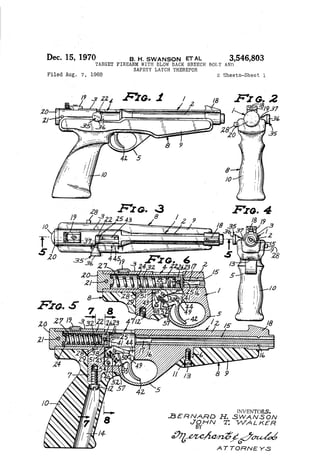
FIG. 1 is a view in side elevation of a target pistol
produced in accordance with this invention;
FIG. 2 is a view in rear elevation;
FIG. 3 is a view in top plan;
FIG. 4 is a view in front elevation;
FIG. 5 is a view in longitudinal section, taken sub
stantially on the ‘line 5—-5 of FIG. 3;
FIG. 6 is a view corresponding to a portion of FIG.
5, but showing a different position of some of the parts;
FIGS. 7 and 8 are enlarged fragmentary transverse sec
10
20
70
3,546,803
Patented Dec. 15, 1970‘ice
2
tions taken on the lines 7—-7 and 8—8 respectively of
FIG. 5;
FIGS. 9 and 10 are views in perspective of the trigger
and sear respectively of this invention.
FIG. 11 is a view in perspective of the breech bolt of
this invention;
FIGS. 12 and 13 are views in side and end elevations
respectively of a cover plate;
FIG. 14 is a view in side elevation of a modi?ed ‘form
of the frame and barrel; and
FIG. 15 is a view in longitudinal section of the frame
and barrel of FIG. 14.
DETAILED DESCRIPTION
The present invention relates to target ri?es, as well as
pistols and, for the purpose of disclosure, 9. target pistol
is shown in the drawings. In the embodiment of the in
vention illustrated in FIGS. l—l3, a unitary frame ele
ment 1 includes a front barrel mounting portion 2 and a
rear tubular receiver portion 3 cooperating with the bar
rel mounting portion 2 to de?ne an opening 4 therebe~
tween. The frame element 1 further de?nes a trigger
guard 5 and front and rear mounting lugs 6 and 7 re
spectively. A one-piece stock 8‘ comprises a fore-end por
tion 9 and a grip portion 10 that is rigidly secured to the
frame element 1 by machine screws 11 and 12 screw
threaded into the bosses 6 and 7 respectively, through
openings 13 and 14 in the fore-end and grip portions 9
and 10 respectively.
Preferably, the frame element 1 is molded or die cast
of a zinc based alloy or similar material, the barrel
mounting portion 2 being molded around a ri?ed barrel
15, the ‘barrel 15 de?ning a pair of longitudinally spaced
annular grooves 16 that receive the frame material, so
that the barrel 15 is securely anchored in place. The
rear end portion of the barrel 15 terminates at the front
end of the opening 4, and is formed to provide a counter
bored cartridge receiving chamber portion 17. The frame
element 1 is further formed to provide a front sight 18,
the receiver portion 3 having mounted thereon a rear
sight 19 that is preferably adjustable for both elevation
and windage. The rear sight 19 is of the conventional
type usually found on target pistols. The rear end of the
receiver portion '3 is provided with a stop plug 20, the
receiver portion 3 and stop plug 20 being cross-drilled to
slidably receive an anchoring pin 21 for releasably hold
ing the stop plug 20 in place.
An elongated cylindrical breech bolt 22 is axially
slidably mounted within the tubular receiver 3, and has
a closed from end 23 and an open rear end 24, the
breech bolt 22 being movable between a forward posi
tion in abutting relationship with the rear end of the
barrel 15 to close the chamber 17, as shown by full
lines in FIG. 6, and a pair of axially spaced rearward
positions as shown by full and dotted lines in FIG. 5.
A ?ring pin 25 is ?xed to and projects forwardly from
the closed front end 23, and projects into the counter
bored portion of the chamber 17 when the breech bolt
22 is in its forward ?ring position of FIG. 6. The breech
bolt 22 is axially aligned with the barrel 15, and the
?ring pin 25, which is preferably integrally formed with
the breech bolt 22, is displaced from the axis of the
‘breech bolt 22 for use with rim ?re cartridges. With a
?rearm using center ?re cartridges, the ?ring pin 25 is
disposed on the common axis of the breech bolt 22 and
barrel 15. A retainer plug 26 is disposed within the
breech bolt 22, adjacent the closed end 23 thereof, and
recoil spring 27 is interposed between the stop plug 20
and retainer plug 26, to yieldingly urge the breech bolt
22 toward its ‘fully advanced or ?ring position against the
rear end of the barrel 15.
4. 3,546,808a
a
The breech bolt 22 is releasably held in its rearward
most or loading position, shown by full lines in FIG.
5, by a safety latch ‘member in the nature of a cross
sectionally rectangular bar 28 that is axially slidably
mounted in aligned transverse passages 29 and 30 in the
receiver portion ‘3 and stock 8 respectively, see par
ticularly FIG. 7. As there shown, the passage 30 has a
closed end in the stock 8, a coil compression spring 31
being disposed in the closed end of the passage 30 and
yieldingly urging the latch member or bar axially out
wardly of the passages 29 and 30. The latch member 28 is
formed intermediate its ends with an upwardly opening
notch 32, one end of which de?nes a lug portion 33 that
is receivable in a recess 34 in the sidewall of the breech
bolt 22. It will be noted that the aligned passages 29‘ and
30 are so disposed relative to the breech bolt 22 that a
portion of the breech bolt 22 moves transversely through
the notch 32, and that the spring 31 urges the lug 33
into the recess 34 when the recess 34 is in register with
the passage 29 at the rearmost position of the breech
bolt 22. The breech bolt 22 is released for recoil spring
imparted forward movement by ‘manually exerting axial
pressure on the outer exposed end of the latch member
28 against bias of the spring 31.
A breech bolt handle 35 comprises a knob portion 36
having a reduced neck portion 37, an axial stem portion
38 of less diameter than that of the neck portion 37, and
a head portion 39 having a diameter substantially equal
to that of the neck portion 37. The head portion 39 and
adjacent end of the stem portion 37 are received in ‘’
aligned transverse openings 40 in the breech block 22,
the stem portion 38 being received in a forwardly open
ing slot or groove 41 in the retainer plug 26. The handle
35 is used to initially move the breech bolt 22 rearwardly
to its rearmost or loading position against bias of the
recoil spring 27. Thereafter, the ?ring of a cartridge
causes the breech bolt 22 to be automatically moved to
its rearmost or loading position shown ‘by full lines in
FIG. 5, as will be hereinafter described.
A trigger 42 and a cooperating sear 43 are disposed
in the lower portion 44 of the opening 4, said lower
portion 44 being partially closed by a cover element 45.
The cover element ‘45 is provided with a pair of laterally
inwardly projecting bosses 46 and 47, the former of
which has its free end seated in a recess 48 in the frame
element 1, and the latter of which cooperates with a
boss 49 that projects transversely of the frame element
1 in axial alignment with the boss 47 to pivotally mount
the trigger 42. The sear 43 is pivotally mounted on a
transverse stud or boss 50 integrally formed with the
frame element 1, and has an abutment portion 51 that
is adapted to engage the front end 23 of the breech bolt
22 to releasably hold the breech bolt 22 in a cocked po
sition slightly forwardly of its loading position, as in
dicated by dotted lines in FIG. 5. The trigger 42 and sear
43 are yieldingly urged toward positions shown in FIG.
5, wherein the abutment portion 51 is disposed in the
path of travel of the breech bolt 22, by a coil compres
sion spring 52 having its opposite ends mounted on re
taining ?ngers or the like 53 and 54 on the trigger and
sear respectively. The trigger 42 is formed to provide
a cam portion 55 that engages a cooperating surface por
tion 56 on the sear 43, to move the sear in a direction to
release the breech ‘bolt 22, when the trigger 42 is pulled,
for recoil spring imparted movement of the breech bolt
22 to its ?ring position of FIG. 6. The trigger 42 and
sear 43 are held in place in the opening portion 44 by
the cover 45, the cover 45 being releasably held in place
by the stock 8, as shown in FIG. 8. A tail portion 57 of
the trigger 42 engages the frame element 1 at the bottom
of the opening 4 to limit pivotal movement of the trigger
42 in a forward or counterclockwise direction with respect
to FIGS. 5 and 6, pivotal movement of the sear 43 in a
clockwise direction with respect to FIGS. 5 and 6 being
10
20
4
limited by engagement with the trigger 42 adjacent the
cam portion 55 thereof, as shown in FIG. 5.
In operation, assuming that the above-described ?re
arm is unloaded, the user grasps the knob portion 36
and pulls the same rearwardly until the recess 34 of the
breech bolt 22 moves into register with the passage 29
in the frame 1, at which time the safety latch member
28 is spring pressed into locking engagement with the
breech bolt 22 in its loading position. During rearward
movement of the breech bolt 22, the same moves rear
wardly of the abutment portion 51 of the sear 43, per
mitting the spring 52 to move the sear 43 and trigger
42 to their breech bolt holding positions of FIG. 5. A
cartridge, not shown, is then inserted into the cham
ber 17, after which the latch member 28 is manually
pressed laterally inwardly to release the breech bolt 22
which ‘moves forwardly, under bias of the recoil spring
27, into its cocked position wherein the front end 23
thereof engages the abutment portion 51 of the sear
43. The pistol is then aimed and ?red in the usual man
ner by pulling the trigger 42, releasing the breech bolt
22 rearwardly to move the sear 43 to a breech bolt re
lease position shown in FIG. 6 for spring imparted for
ward movement into engagement with the rear end of the
barrel 15, whereupon the ?xed ?ring pin 25 strikes the cap
or primer portion of the cartridge with su?icient force to
discharge the same. As is well known to those familiar
with ?rearms, discharge of the cartridge primer or cap
ignites the powder charge in the cartridge. The expan
sion of gases of combustion in the cartridge not only
propels the bullet thereof forwardly through the barrel
15, but also exerts a recoil force rearwardly against the
cartridge shell and breech bolt 22 to blow the shell rear
wardly of the chamber 17 and move the breech bolt 22
rearwardly against bias of the recoil spring 27, to a point
where the latch member 28 automatically locks the breech
bolt 22 in its loading position, the combustion gases escap
ing upwardly through the opening 4 tending to carry the
empty shell outwardly through said opening 4. The pistol
is then automatically ready to be reloaded. Should the
empty shell fail to be carried away by the gases and re
main within the frame element 1 rearwardly of the barrel,
it may be removed by merely inverting the pistol, per
mitting the shell to drop therefrom by gravity. It is im
portant to note that, when the breech bolt 22 is held
in its loading position by the safety latch member 28,
the pistol cannot be accidentally discharged by pulling
on the trigger 42, inasmuch as the sear 43 does not en
gage the breech bolt 22 in its loading position. After each
?ring, the safety latch member 28 must be pressed in
wardly to permit the breech bolt 22 to advance to its
cocked position.
An important feature of this invention resides in the
simplicity of its construction and in the ease with which
the same may be disassembled for cleaning and oiling,
and reassembled for use. To disassemble the pistol, the
anchoring pin 21 is ?rst withdrawn from the stop plug
20 and receiver portion 3, permitting the stop plug 20
and recoil spring 27 to drop rearwardly outwardly from
the receiver portion 3 and breech bolt 22 when the pistol
is tilted rearwardly downwardly. The retained plug 26‘,
which is loosely received in the breech bolt 22 will also
drop therefrom and out of engagement with the handle
stem portion 38, permitting the handle 35 to be with
drawn from the breech bolt 22. Then, when the safety
latch member 28 is pressed inwardly to disengage the
lug 33 from the recess 34, the breech bolt 22 may be
slidably moved rearwardly out of the receiver portion
3. The latch member 28 may then be manually with
drawn from the aligned passages 29 and 30. With re
moval of the safety latch member 28, the stock 8 may be
disassembled from the frame 1 by removing the screws
11 and 12, after which the cover 45 may be lifted out
of engagement with the frame element 1 and the trigger
42 and sear 43 drawn axially out of engagement with
5. 3,546,803
their respective bosses 49 and 50. The pistol is reas
sembled in the reverse order. Thus, it will be seen that
a screw driver and a punch or nail are all that are re
quired for complete disassembly and reassembly of the
pistol.
The modi?ed form of the invention illustrated in
FIGS. 14 and 15 comprises a frame element 58 that is
quite similar to the frame element 1, but which is adapted
to removably mount a barrel 59. In this form of the
invention, the frame element 58 is provided with a screw
threaded opening 60 for reception of the screw threaded
rear end portion 61 of the barrel 59, the frame element
58 further including a forwardly projecting rib 62 dis
posed in overlying spaced relation to the barrel 59 to pro
vide ventilation therebetween. At its front end, the rib
62 is formed to provide a front sight 63 and a barrel
supporting ring 64. With this arrangement, the barrel 59
may be easily removed from the frame element 58 pro
viding for interchangeability with barrels of different
lengths and calibers. The rear end portion of the frame
element 58, including the mounting lugs and trigger guard
is identical to that of the frame element 1, and parts
thereof corresponding to similar parts of the frame ele
ment 1 are identi?ed by the same reference numerals,
prime marks added.
A target pistol or ri?e made in accordance with this
invention may be produced at extremely low cost, by
utilizing die castings, stamped and turned parts, and by
making the stock 8 of molded synthetic plastic material.
A target pistol produced in accordance with this inven
tion has been found to be extremely accurate and durable
in its operation.
What is claimed is:
1. A target ?rearm comprising:
(a) a unitary frame element including a barrel mount
ing portion and a tubular receiver portion rearwardly
of the barrel mounting portion, said frame element
de?ning a cartridge and ?ring mechanism receiving
opening intermediate said receiver portion and barrel
mounting portion,
(b) a tubular barrel mounted in said barrel mounting
portion and de?ning a cartridge receiving chamber
at its rear end adjacent said frame element opening,
(0) an elongated breech bolt mounted for axial sliding
movements in said receiver portion and having a
front end movable forwardly into and rearwardly
away from abutting engagement with said rear end
of the barrel to alternately open and close said
chamber,
(d) a ?ring pin ?xed to and projecting forwardly of
said front end of the breech bolt,
(e) yielding means urging said breech bolt toward said
engagement thereof with the barrel,
(f) a cover element for a portion of said opening
mounted on said frame element,
(s) a trigger,
(h) a trigger operated sear engaging said breech bolt
to releasably hold said breech bolt in a partially re
tracted cocked position rearwardly spaced from said
barrel,
(i) means mounting said sear and trigger in said open
ing for pivotal movements between breech bolt hold
ing and release positions relative to said frame
element and breech bolt,
(j) and spring means urging said sear and trigger
toward said breech bolt holding positions thereof.
2. The target ?rearm de?ned in claim 1, in which said
20
30
40
45
50
55
60
65
6
spring means comprises a single coil compression spring
interposed between cooperating portions of said scar and
trigger, said sear having an abutment portion engaging
the front end of said breech bolt, said sear and trigger
having cooperating cam surface portions operative to im
part breech bolt releasing movement to the sear respon
sive to ?ring movement of the trigger against yielding
bias of the compression spring therebetween.
3. The target ?rearm de?ned in claim 1, characterized
by a one-piece stock means including grip and fore-end
portions having seating engagement with said receiver and
barrel mounting portions respectively, and a pair of
mounting screws anchoring said grip and fore-end por
tions to the receiver and barrel mounting portions respec
tively, said pair of mounting screws being the sole means
for anchoring the stock means to said frame.
4. The target ?rearm de?ned in claim 1, characterized
by a safety latch member mounted in said frame element
for movements toward and away from latching engage
ment with said breech bolt for automatically and releas
ably holding said breech bolt in a fully retracted loading
position rearwardly of said cocked position thereof.
5. The target ?rearm de?ned in claim 4, in which said
safety latch member includes a breech bolt engaging lug
portion Within said frame element and a manually engage
able portion projecting outwardly of said frame element,
characterized by yielding means urging said safety latch
member in a direction to move said lug portion toward
latching engagement with said bolt.
6. The target ?rearm de?ned in claim 1 in which said
breech bolt comprises a tubular member having a closed
front end and an open rear end, characterized by a plug
element removably mounted in the rear end of said tubu
lar receiver portion, said ?rst mentioned yielding means
comprising a recoil spring extending within said breech
bolt and having one end engaging said plug element.
7. The target ?rearm de?ned in claim 6, in which
said ?ring pin is integrally formed with said breech bolt
and projects forwardly thereof.
8. The target ?rearm de?ned in claim 6 characterized
by a cooking handle projecting transversely outwardly of
said frame element opening and comprising a knob por
tion and a stern portion having an enlarged head on its
end opposite said handle portion, said breech bolt having
a transverse opening therethrough rearwardly of the
closed end thereof for reception of said head, and in fur
ther combination with a retainer element interposed be
tween said recoil spring and the closed end of the breech
bolt, said retainer element having a forwardly opening
notch for reception of the stem portion of said cocking
handle, whereby to hold the cocking handle against move
ment transversely of said breech bolt.
References Cited
UNITED STATES PATENTS
1,405,765 2/1922 Diehm _____________ __ 42—16
2,406,493 8/1946 Dunn ________________ 42—69
2,848,831 8/1958 McLaughlin ________ __ 42—~—16
2,882,634 4/1959 Smith ________________ 42—16
2,940,202 6/1960 Harper _____________.. 42—16
BENJAMIN A. BORCHELT, Primary Examiner
C. T. JORDAN, Assistant Examiner
U.S. CI. X.R.
42—69