Biswanath Byam Samiti Open Quiz 2022 by Qui9 Grand Finale
Iluminacion
1. Visual Realism
Shading and Illumination
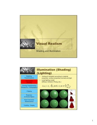
Illumination (Shading)
(Lighting)
Modeling • Vertices lit (shaded) according to material
Transformations properties, surface properties (normal) and light
Illumination • Local lighting model
(Shading) (Diffuse, Ambient, Phong, etc.)
Viewing Transformation
(Perspective / Orthographic)
(
L(ωr ) = k a + k d (n ⋅ l) + k s (v ⋅ r ) q ) 4π d
Φs
2
Clipping
Projection
(to Screen Space)
Scan Conversion
(Rasterization)
Visibility / Display
1
3. Lighting vs. Shading
• lighting
– simulating the interaction of light with surface
• shading
– deciding pixel color
– continuum of realism: when do we do lighting
calculation?
Modeling Light
Sources
• IL(x,y,z,θ,φ,λ) ...
– describes the intensity of energy,
– leaving a light source, …
– arriving at location(x,y,z), ...
(x,y,z)
– from direction (θ,φ), ...
– with wavelength λ
Light
3
4. Empirical Models
• Ideally measure irradiant energy for “all”
situations
– Too much storage
– Difficult in practice
λ
Light Sources
• directional/parallel lights
• point at infinity: (x,y,z,0)T
• point lights
• finite position: (x,y,z,1)T
• spotlights
• position, direction, angle
• ambient lights
4
5. Ambient Light Sources
• Objects not directly lit are typically still visible
– e.g., the ceiling in this room, undersides of desks
• This is the result of indirect illumination from emitters,
bouncing off intermediate surfaces
• Too expensive to calculate (in real time), so we use a
hack called an ambient light source
– No spatial or directional characteristics; illuminates all
surfaces equally
– Amount reflected depends on surface properties
Ambient Light Sources
• For each sampled wavelength (R, G, B),
the ambient light reflected from a surface
depends on
– The surface properties, kambient
– The intensity, Iambient, of the ambient light
source (constant for all points on all surfaces )
• Ireflected = kambient Iambient
5
6. Ambient Light Sources
• scene lit only with an ambient light source
Light Position
Not Important
Viewer Position
Not Important
Surface Angle
Not Important
Ambient Term
• Represents reflection of all indirect
illumination
This is a total hack (avoids complexity of global illumination)!
6
7. Directional Light
Sources
• For a directional light source we make
simplifying assumptions
– Direction is constant for all surfaces in the scene
– All rays of light from the source are parallel
• As if the source were infinitely far away
from the surfaces in the scene
• A good approximation to sunlight
• The direction from a surface to the light source
is important in lighting the surface
Directional Light
Sources
• scene lit with directional and ambient light
Light Position
Not Important
Surface Angle
Important
Viewer Position
Not Important
7
8. Point Light Sources
• A point light source emits light equally in
all directions from a single point
• The direction to the light from a point on a
surface thus differs for different points:
– So we need to calculate a l
normalized vector to the light
source for every point we light:
p
Point Light Sources
• scene lit with ambient and point light source
Light Position
Important
Viewer Position
Important
Surface Angle
Important
8
9. Other Light Sources
• Spotlights are point sources whose
intensity falls off directionally.
– Requires color, point
direction, falloff
parameters
– Supported by OpenGL
Other Light Sources
• Area light sources define a 2-D emissive
surface (usually a disc or polygon)
– Good example: fluorescent light panels
– Capable of generating soft shadows (why? )
9
10. Light Transport Assumptions II
• color approximated by discrete wavelengths
– quantized approx of dispersion (rainbows)
– quantized approx of fluorescence (cycling vests)
• no propagation media (surfaces in vacuum)
– no atmospheric scattering (fog, clouds)
• some tricks to simulate explicitly
– no refraction (mirages)
Light Transport Assumptions III
• light travels in straight line
– no gravity lenses
• superposition (lights can be added)
– no nonlinear reflection models
• nonlinearity handled separately
10
11. Illumination
• transport of energy from light sources to
surfaces & points
– includes direct and indirect illumination
Images by Henrik Wann Jensen
Components of Illumination
• two components: light sources and surface properties
• light sources (or emitters)
– spectrum of emittance (i.e., color of the light)
– geometric attributes
• position
• direction
• shape
– directional attenuation
– polarization
11
12. Components of
Illumination
• surface properties
– reflectance spectrum (i.e., color of the surface)
– subsurface reflectance
– geometric attributes
• position
• orientation
• micro-structure
Modeling Surface
Reflectance
• Rs(θ,φ,γ,ψ,λ) ...
– describes the amount of incident energy,
– arriving from direction (θ,φ), ...
– leaving in direction (γ,ψ), … λ
– with wavelength λ
(θ,φ)
(ψ,λ)
Surface
12
13. Empirical Models
• Ideally measure radiant energy for “all”
combinations of incident angles
– Too much storage
– Difficult in practice λ
(θ,φ)
(ψ,λ)
Surface
Types of Reflection
• specular (a.k.a. mirror or regular)
reflection causes light to propagate
without scattering.
• diffuse reflection sends light in all
directions with equal energy.
• mixed reflection is a weighted
combination of specular and diffuse.
13
14. Types of Reflection
• retro-reflection occurs when incident
energy reflects in directions close to the
incident direction, for a wide range of
incident directions.
• gloss is the property of a material surface
that involves mixed reflection and is
responsible for the mirror like appearance
of rough surfaces.
Reflectance Distribution
Model
• most surfaces exhibit complex reflectances
– vary with incident and reflected directions.
– model with combination
+ + =
specular + glossy + diffuse =
reflectance distribution
14
15. Surface Roughness
• at a microscopic scale,
all real surfaces are
rough
• cast shadows on
themselves shadow shadow
• “mask” reflected light:
Masked Light
Surface Roughness
• notice another effect of roughness:
– each “microfacet” is treated as a perfect mirror.
– incident light reflected in different directions by
different facets.
– end result is mixed reflectance.
• smoother surfaces are more specular or glossy.
• random distribution of facet normals results in diffuse
reflectance.
15
16. Physics of Reflection
• ideal diffuse reflection
– very rough surface at the microscopic level
• real-world example: chalk
– microscopic variations mean incoming ray of light
equally likely to be reflected in any direction over
the hemisphere
– what does the reflected intensity depend on?
Lambert’s Cosine Law
• ideal diffuse surface reflection
the energy reflected by a small portion of a surface from a light
source in a given direction is proportional to the cosine of the
angle between that direction and the surface normal
• reflected intensity
– independent of viewing direction
– depends on surface orientation with respect to
light
• often called Lambertian surfaces
16
17. Lambert’s Law
intuitively: cross-sectional area of
the “beam” intersecting an element
of surface area is smaller for greater
angles with the normal.
Diffuse Reflection
• How much light is reflected?
– Depends on angle of incident light
θ dL
dL = dA cos Θ
dA
Surface
17
18. Computing Diffuse Reflection
• angle between surface normal and incoming
light is angle of incidence: k : d
l n diffuse component
”surface color”
θ
Idiffuse = kd Ilight cos θ
• in practice use vector arithmetic
Idiffuse = kd Ilight (n • l)
Diffuse Lighting Examples
• Lambertian sphere from several lighting
angles:
• need only consider angles from 0° to 90°
• why?
– demo: Brown exploratory on reflection
18
19. Specular Reflection
• shiny surfaces exhibit specular reflection
– polished metal diffuse
diffuse
– glossy car finish
plus
specular
• specular highlight
– bright spot from light shining on a specular surface
• view dependent
– highlight position is function of the viewer’s position
Physics of Reflection
• at the microscopic level a specular
reflecting surface is very smooth
• thus rays of light are likely to bounce off
the microgeometry in a mirror-like fashion
• the smoother the surface, the closer it
becomes to a perfect mirror
19
20. Optics of Reflection
• reflection follows Snell’s Law:
– incoming ray and reflected ray lie in a plane
with the surface normal
– angle the reflected ray forms with surface
normal equals angle formed by incoming ray
and surface normal
θ(l)ight = θ(r)eflection
Non-Ideal Specular Reflectance
•Snell’s law applies to perfect mirror-like surfaces, but
aside from mirrors (and chrome) few surfaces exhibit
perfect specularity
• how can we capture the “softer”
reflections of surface that are glossy
rather than mirror-like?
• one option: model the microgeometry of the surface
and explicitly bounce rays off of it
• or…
20
21. Empirical
Approximation
• we expect most reflected light to travel in
direction predicted by Snell’s Law
• but because of microscopic surface variations,
some light may be reflected in a direction slightly
off the ideal reflected ray
• as angle from ideal reflected ray increases, we
expect less light to be reflected
Empirical
Approximation
• angular falloff
• how might we model this falloff?
21
22. Phong Lighting
• most common lighting model in computer graphics
• (Phong Bui-Tuong, 1975)
nshiny
Ispecular =k s Ilight ( cos φ )
• The nshiny term is a purely v
empirical constant that
varies the rate of falloff
• Though this model has no
physical basis, it works
(sort of) in practice
Phong Lighting: The nshiny Term
• Phong reflectance term drops off with divergence of
viewing angle from ideal reflected ray
Viewing angle – reflected angle
• what does this term control, visually?
22
23. Phong Examples
varying l
varying nshiny
Calculating Phong
Lighting
• The cos term of Phong lighting can be
computed using vector arithmetic:
Ispecular = ksIlight (v ⋅ r ) shiny
n
v
– v: unit vector towards viewer
– r: ideal reflectance direction
– ks: specular component
• highlight color
• how to efficiently calculate r ?
23
24. Calculating The R Vector
P = N cos θ = projection of L onto N
P+S=R L
P
N cos θ + S = R
S = P – L = N cos θ - L S N S
N cos θ + (N cos θ – L) = R P
L
2 ( N cos θ ) – L = R θ R
cos θ = N · L P=N(N·L)
2 ( N (N · L)) – L = R 2P=R+L
2P–L=R
N and R are unit length! 2 (N ( N · L )) - L = R
Combining Everything
• Simple analytic model:
– diffuse reflection +
– specular reflection +
– emission +
– “ambient”
Surface
24
25. Combining Everything
• Simple analytic model:
– diffuse reflection +
– specular reflection +
– emission +
– “ambient”
Surface
The Final Combined
Equation
• Single light source:
N
Viewer R θ θ L
α
V
I = I E + K A I AL + K D ( N • L) I L + K S (V • R ) n I L
25
26. Final Combined
Equation
• Multiple light sources:
N
Viewer L1
L2
V
I = I E + K A I AL + ∑i ( K D ( N • Li ) I i + K S (V • Ri ) n I i )
The Phong Lighting
Model
• combine ambient, diffuse, specular components
I = I E + K A I AL + ∑i ( K D ( N • Li ) I i + K S (V • Ri ) n I i )
• commonly called Phong lighting
– once per light
– once per color component
26
27. Phong Lighting: Intensity Plots
Lighting Review
• lighting models
– ambient
• normals don’t matter
– Lambert/diffuse
• angle between surface normal and light
– Phong/specular
• surface normal, light, and viewpoint
27
28. Blinn-Phong Model
• variation with better physical interpretation
• Jim Blinn, 1977
– h: halfway vector
– highlight occurs when h near n
nshiny
I out (x) = ks ⋅ (h ⋅ n) ⋅ I in (x); with h = (l + v ) / 2
h n
v
l
Light Source Falloff
• non-quadratic falloff
– many systems allow for other falloffs
– allows for faking effect of area light sources
– OpenGL / graphics hardware
• Io: intensity of light source
• x: object point
• r: distance of light from x
1
I in (x) = ⋅ I0
ar 2 + br + c
28
29. Anisotropy
• so far we’ve been considering isotropic
materials.
– reflection and refraction invariant with respect
to rotation of the surface about the surface
normal vector.
– for many materials, reflectance and
transmission are dependent on this azimuth
angle: anisotropic reflectance/transmission.
– examples?
Activity
What are the differences?
29
30. 1 2
3
Lighting vs. Shading
• lighting: process of computing the
luminous intensity (i.e., outgoing light) at a
particular 3-D point, usually on a surface
• shading: the process of assigning colors
to pixels
(why the distinction?)
30
31. Applying Illumination
• we now have an illumination model for a point
on a surface
• if surface defined as mesh of polygonal facets,
which points should we use?
– fairly expensive calculation
– several possible answers, each with different
implications for visual quality of result
Applying Illumination
• polygonal/triangular models
– each facet has a constant surface normal
– if light is directional, diffuse reflectance is
constant across the facet.
– why?
31
32. Flat Shading
• simplest approach calculates illumination at a
single point for each polygon
• obviously inaccurate for smooth surfaces
Flat Shading
Approximations
• if an object really is
faceted, is this accurate?
• no!
– for point sources, the
direction to light varies
across the facet
– for specular reflectance,
direction to eye varies
across the facet
32
33. Improving Flat Shading
• what if evaluate Phong lighting model at
each pixel of the polygon?
– better, but result still clearly faceted
• for smoother-looking surfaces
we introduce vertex normals at each
vertex
– usually different from facet normal
– used only for shading
– think of as a better approximation of the real
surface that the polygons approximate
Vertex Normals
• vertex normals may be
– provided with the model
– computed from first principles
– approximated by
averaging the normals
of the facets that
share the vertex
33
34. Gouraud Shading
• most common approach, and what OpenGL does
– perform Phong lighting at the vertices
– linearly interpolate the resulting colors over faces
• along edges
• along scanlines
edge: mix of c1, c2 C1
does this eliminate the facets?
C3
C2
interior: mix of c1, c2, c3
edge: mix of c1, c3
Gouraud Shading
Artifacts
• often appears dull, chalky
• lacks accurate specular component
– if included, will be averaged over entire
polygon
C1
C3
C2 Can’t shade that effect!
34
35. Gouraud Shading
Artifacts
• Mach bands
– eye enhances discontinuity in first derivative
– very disturbing, especially for highlights
Gouraud Shading
Artifacts
• Mach bands
C1
C4
C3
C2
Discontinuity in rate
of color change
occurs here
35
36. Gouraud Shading Artifacts
• Gouraud shading can miss specular highlights in specular objects
because it interpolates vertex colors instead of vertex normals
– here Na and Nb would cause no appreciable specular
component, whereas Nc would. Shading by interpolating
between Ia and Ib , therefore misses the highlight that
evaluating I at c would catch
• Interpolating the normal
comes closer to what the
actual normal of the
surface being polygonally
approximated would be
Flat vs. Gouraud
Shading
glShadeModel(GL_FLAT) glShadeModel(GL_SMOOTH)
Flat - Determine that each face has a single normal, and
color the entire face a single value, based on that
normal.
Gouraud – Determine the color at each vertex, using the
normal at that vertex, and interpolate linearly for the
pixels between the vertex locations.
36
37. Phong Shading
• linearly interpolating surface normal
across the facet, applying Phong lighting
model at every pixel
– same input as Gouraud shading
– pro: much smoother results
– con: considerably more expensive
• not the same as Phong lighting
– common confusion
– Phong lighting: empirical model to calculate
illumination at a point on a surface
Phong Shading
• linearly interpolate the vertex normals
– compute lighting equations at each pixel
– can use specular component
( ) ( )
#lights
∑ I i ⎛ k d N ⋅ Li + k s V ⋅ Ri
ˆ ˆ ˆ ˆ ⎞
nshiny
I total = k a I ambient + ⎜ ⎟
N1 i =1 ⎝ ⎠
remember: normals used in
diffuse and specular terms
N4
N3
discontinuity in normal’s rate of
change harder to detect
N2
37
38. Phong Shading
Difficulties
• computationally expensive
– per-pixel vector normalization and lighting
computation!
– floating point operations required
• lighting after perspective projection
– messes up the angles between vectors
– have to keep eye-space vectors around
• no direct support in hardware
– but can be simulated with texture mapping
Shading Artifacts: Silhouettes
• polygonal silhouettes remain
Gouraud Phong
38
39. Shading Artifacts: Orientation
• interpolation dependent on polygon orientation
A
Rotate -90o
B
and color
i same point C
B D A
i
D
C
Interpolate between Interpolate between
AB and AD CD and AD
Shading Artifacts: Shared Vertices
vertex B shared by two rectangles
on the right, but not by the one on
D C H the left
first portion of the scanline
B G is interpolated between DE and AC
second portion of the scanline
is interpolated between BC and GH
E F
A
a large discontinuity could arise
39
40. Shading Models
Summary
• flat shading
– compute Phong lighting once for entire polygon
• Gouraud shading
– compute Phong lighting at the vertices and
interpolate lighting values across polygon
• Phong shading
– compute averaged vertex normals
– interpolate normals across polygon and perform
Phong lighting across polygon
Shutterbug: Flat
Shading
40
![Photorealistic
Illumination
[electricimage.com]
electricimage.com]
Photorealistic
Illumination
[electricimage.com]
electricimage.com]
2](data:image/gif;base64,R0lGODlhAQABAIAAAAAAAP///yH5BAEAAAAALAAAAAABAAEAAAIBRAA7)