A practical guide to free energy devices pages 23 32 - patrick j. kelly
•
2 j'aime•7,260 vues

This document discusses permanent magnet motors and generators. It begins by explaining how permanent magnets work and debunking the idea that they cannot do work. It then summarizes several designs for permanent magnet motors and generators, including ones that use rotating magnetic shields to produce power without resistance. Key designs discussed include those by John Bedini, Wang Shum Ho, John Ecklin, and Howard Johnson. The document emphasizes that permanent magnets can power generators indefinitely without external fuel.

Recommandé
Contenu connexe
Tendances
Tendances (20)
Similaire à A practical guide to free energy devices pages 23 32 - patrick j. kelly
Similaire à A practical guide to free energy devices pages 23 32 - patrick j. kelly (20)
Plus de Mrinal Pal
Plus de Mrinal Pal (19)
Dernier
Dernier (9)
A practical guide to free energy devices pages 23 32 - patrick j. kelly
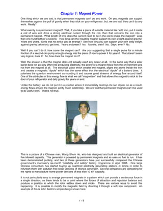
- 1. Chapter 1: Magnet Power One thing which we are told, is that permanent magnets can’t do any work. Oh yes, magnets can support themselves against the pull of gravity when they stick on your refrigerator, but, we are told, they can’t do any work. Really? What exactly is a permanent magnet? Well, if you take a piece of suitable material like ‘soft’ iron, put it inside a coil of wire and drive a strong electrical current through the coil, then that converts the iron into a permanent magnet. What length of time does the current need to be in the coil to make the magnet? Less than one hundredth of a second. How long can the resulting magnet support its own weight against gravity? Years and years. Does that not strike you as strange? See how long you can support your own body weight against gravity before you get tired. Years and years? No. Months, then? No. Days, even? No. Well if you can’t do it, how come the magnet can? Are you suggesting that a single pulse for a minute fraction of a second can pump enough energy into the piece of iron to power it for years? That doesn’t seem very logical, does it? So, how does the magnet do it? Well, the answer is that the magnet does not actually exert any power at all. In the same way that a solar panel does not put any effort into producing electricity, the power of a magnet flows from the environment and not from the magnet at all. The electrical pulse which creates the magnet, aligns the atoms inside the iron and creates a magnetic “dipole” which has the same effect that the electrical “dipole” of a battery does. It polarises the quantum environment surrounding it and causes great streams of energy flow around itself. One of the attributes of this energy flow is what we call “magnetism” and that allows the magnet to stick to the door of your refrigerator and defy gravity for years on end. Unlike the battery, we do not put it in a position where it immediately destroys its own dipole, so as a result, energy flows around the magnet, pretty much indefinitely. We are told that permanent magnets can’t be used to do useful work. That is not true. This is a picture of a Chinese man, Wang Shum Ho, who has designed and built an electrical generator of five kilowatt capacity. This generator is powered by permanent magnets and so uses no fuel to run. It has been demonstrated publicly, and two of these generators have just successfully completed the Chinese government’s mandatory six-month “reliability and safety” testing programme in April 2008. One large Chinese consortium has started buying up coal-fired electricity generating stations in China in order to refurbish them with pollution-free large versions of Wang’s generator. Several companies are competing for the rights to manufacture home-power versions of less than 10 kW capacity. It is not particularly easy to arrange permanent magnets in a pattern which can provide a continuous force in a single direction, as there tends to be a point where the forces of attraction and repulsion balance and produce a position in which the rotor settles down and sticks. There are various ways to avoid this happening. It is possible to modify the magnetic field by diverting it through a soft iron component. An example of this is John Bedini’s simple design shown here: 1-9
- 2. In John’s design, the magnetic field of the stator magnet is altered by the iron yoke and this smothers the repulsion which would normally occur between the North pole of the stator magnet and the North pole of each rotor magnet as it gets close to the stator magnet. This arrangement allows the rotor magnets to receive a push as they pass by the stator magnet, producing a repeating thrust to keep the rotor rotating. To increase the power, there does not appear to be any reason why there should not be two stators as shown here: 1 - 10
- 3. There does not appear to be any reason why several of these rotor/stator assemblies should not be attached to a single shaft to increase the power applied to the shaft and allow an increased level of useful work to be performed by the device. There are many other designs of permanent magnet motor, but before showing some of them, it is probably worth discussing what useful work can be performed by the rotating shaft of a permanent magnet motor. With a home-built permanent magnet motor, where cheap components have been used and the quality of workmanship may not be all that great (though that is most definitely not the case with some home construction), the shaft power may not be very high. Generating electrical power is a common goal, and that can be achieved by causing permanent magnets to pass by coils of wire. The closer to the wire coils, the greater the power generated in those coils. Unfortunately, doing this creates magnetic drag and that drag increases with the amount of electrical current being drawn from the coils. There are ways to reduce this drag on the shaft rotation. One way is to use an Ecklin-Brown style of electrical generator, where the shaft rotation does not move magnets past coils, but instead, moves a magnetic screen which alternatively blocks and restores a magnetic path through the generating coils. A commercially available material called “mu-metal” is particularly good as magnetic shield material and a piece shaped like a plus sign is used in the Ecklin-Brown generator. John W. Ecklin was granted US Patent Number 3,879,622 on 29th March 1974. The patent is for a magnet/electric motor generator which produces an output greater than the input necessary to run it. There are two styles of operation. The main illustration for the first is: Here, the (clever) idea is to use a small low-power motor to rotate a magnetic shield to mask the pull of two magnets. This causes a fluctuating magnet field which is used to rotate a generator drive. In the diagram above, the motor at point ‘A’ rotates the shaft and shielding strips at point ‘B”. These rectangular mu-metal strips form a very conductive path for the magnetic lines of force when they are lined up with the ends of the magnets and they effectively shut off the magnet pull in the area of point ‘C’. At point ‘C’, the spring-loaded traveller is pulled to the left when the right-hand magnet is shielded and the left hand magnet is not shielded. When the motor shaft rotates further, the traveller is pulled to the right when the left- hand magnet is shielded and the right hand magnet is not shielded. This oscillation is passed by mechanical linkage to point ‘D’ where it is used to rotate a shaft used to power a generator. As the effort needed to rotate the magnetic shield is relatively low, it is claimed that the output exceeds the input and so can be used to power the motor which rotates the magnetic shield. The second method for exploiting the idea is shown in the patent as: 1 - 11
- 4. Here, the same shielding idea is utilised to produce a reciprocating movement which is then converted to two rotary motions to drive two generators. The pair of magnets ‘A’ are placed in a housing and pressed towards each other by two springs. When the springs are fully extended, they are just clear of the magnetic shield ‘B’. When a small electric motor (not shown in the diagram) moves the magnetic shield out of the way, the two magnets are strongly repelled from each other as their North poles are close together. This compresses the springs and through the linkages at ‘C’ they turn two shafts to generate output power. A modification of this idea is the Ecklin-Brown Generator. In this arrangement, the movable magnetic shielding arrangement provides a direct electrical output rather than a mechanical movement: Here, the same motor and rotating magnetic shield arrangement is used, but the magnetic lines of force are blocked from flowing through a central I-piece. This I-piece is made of laminated iron slivers and has a pickup coil or coils wound around it. The device operates as follows: In the position shown on the left, the magnetic lines of force flow downwards through the pickup coils. When the motor shaft has rotated a further ninety degrees, the situation on the right occurs and there, the magnetic lines of force flow upwards through the pickup coils. This is shown by the blue arrows in the diagram. This reversal of magnetic flux takes place four times for every rotation of the motor shaft. While the Ecklin-Brown design assumes that an electric motor is used to rotate the mu-metal shield, there does not seem to be any reason why the rotation should not be done with a permanent magnet motor. 1 - 12
- 5. Another effective power take-off system is that used by the “Phi Transformer” (“Phi” is pronounced “Fi”). In this design, the magnetic drag is reduced by containing the magnetic flux in a laminated iron ring or “toroid”. Again, the design expects an electric motor to be used to spin the rotor, but there does not seem to be any great reason why a permanent magnet motor should not be used instead. Toroidal shapes are clearly important in many devices which pull in additional energy from the environment, even to the extent that Bob Boyce warns against the high-frequency sequential pulsing of coils wound on a toroid yoke, producing a rotating magnetic field as unpredictable surge events can generate some 10,000 amps of additional current which will burn out the circuit components and can very well trigger a radiant energy build up which can create a lightning strike. Bob himself has been hit by just such a lightning strike and he is lucky to have survived. Lesser systems such as the toroid transformer used in Bob’s electrolyser system are safe even though they generate a power gain. So the many toroidal system designs are definitely worth examining. One of these is the “Phi-Transformer” which looks like a somewhat similar arrangement to the MEG described in Chapter 3. However, it operates in quite a different way: Here, lines of magnetic flux coming from a permanent magnet are channelled through a laminated yoke which is effectively a circular mains transformer core. The difference is in the fact that instead of electronically driving a coil to alter the flux coming from the permanent magnet, in this system the magnet is rotated by a small motor. The performance of this device is impressive. The power required to rotate the magnet is not unduly affected by the current drawn from the coils. The flux is channelled through the laminated iron core and in tests an output of 1200 watts for an input of 140 watts has been achieved, and that is a COP of 8.5 which is very respectable, especially for such a simple device. At http://jnaudin.free.fr/html/dsqromg2.htm a generator design by Dave Squires is shown, dated 1999. All attempts to contact Dave Squires have been unsuccessful, so it is not known if the information there is from tests on a device which has actually been built or if it is just a theoretical design, though it is likely that it was not built at that time. The design is almost identical to the Phi Transformer. A central core is produced by casting the shape shown below, using an amorphous iron powder / epoxy mix. However, as the operating frequency is low at only 50 Hz or 60 Hz, there does not seem to be any reason why normal transformer laminations should not be used, in which case six sets of shims shaped like this: which would make the winding of the coils very much easier as standard bobbins could be slotted into place as the core yoke is being assembled. 1 - 13
- 6. However, the complete core is shaped like this with coils placed in the slots: The thinking behind this arrangement is that the “back-EMF” magnetic flux which normally causes Lenz Law opposition to the free rotation of the magnets around the toroid, is diverted around behind the coil and turned so that instead of hindering the rotation, it actually assists it: The speed of rotation is quoted as being 1,000 rpm for 50 Hz and 1,200 rpm for 60 Hz. The coil windings are suggested as being 180 turns of AWG 14 (16 SWG) for 120 volts AC, at a supposed current of 100 amps, which is seems unrealistic as the maximum current for that size of wire is quoted as being 5.9 amps. The magnets are 2 inches long, 1 inch deep neodymium set into a circular rotor of 12 inch diameter. There can, of course, be more than one rotor on a single shaft, and the number of turns would be doubled for 240 volts AC output. The yoke on which the coils are wound is effectively a series of toroids, though admittedly, not exactly circular is shape. An alternative shape which might be considered would be as shown below where the section carrying the magnetic flux for any one coil is more isolated from the other toroids. It is not clear if making the section which passes through the coil, straight rather than curved, so I will leave that detail to people who are expert in magnetics. 1 - 14
- 7. Returning to permanent magnet motors themselves, one of the top names in this field is Howard Johnson. Howard built, demonstrated and gained US patent 4,151,431 on 24th April 1979, from a highly sceptical patent office for, his design of a permanent magnet motor. He used powerful but very expensive Cobalt/Samarium magnets to increase the power output and demonstrated the motor principles for the Spring 1980 edition of Science and Mechanics magazine. His motor configuration is shown here: The point that he makes is that the magnetic flux of his motor is always unbalanced, thus producing a continuous rotational drive. The rotor magnets are joined in stepped pairs, connected by a non-magnetic yoke. The stator magnets are placed on a mu-metal apron cylinder. Mu-metal is very highly conductive to magnetic flux (and is expensive). The patent states that the armature magnet is 3.125” (79.4 mm) long and the stator magnets are 1” (25.4 mm) wide, 0.25” (6 mm) deep and 4” (100 mm) long. It also states that the rotor magnet pairs are not set at 120 degrees apart but are staggered slightly to smooth out the magnetic forces on the rotor. It also states that the air gap between the magnets of the rotor and the stator are a compromise in that the greater the gap, the smoother the running but the lower the power. So, a gap is chosen to give the greatest power at an acceptable level of vibration. Howard considers permanent magnets to be room-temperature superconductors. Presumably, he sees magnetic material as having electron spin directions in random directions so that their net magnetic field is near zero until the electron spins are aligned by the magnetising process which then creates an overall net permanent magnetic field, maintained by the superconductive electrical flow. The magnet arrangement is shown here, with the inter-magnet gaps assessed from the drawing in Howard’s patent: 1 - 15
- 8. Howard made measurements of the magnetic field strengths and these are shown in the following table: 1 - 16
- 9. the magazine article can be seen at http://newebmasters.com/freeenergy/sm-pg48.html. An artist’s impression of the completed motor-generator set-up with a cut-away section is shown here: 1 - 17
- 10. The Carousel Permanent Magnet Motor/Generator: US Patent 5,625,241 presents the specific details of a simple electrical generator powered by permanent magnets alone. This generator can also be used as a motor. The construction is not particularly complicated: It uses an arrangement where permanent magnets are associated with every second coil set around the rotor. Operation is self-powered and the magnet arrangement is clearly defined: 1 - 18