
Recommandé
Contenu connexe
Tendances
Tendances (19)
Similaire à Sm01b
Similaire à Sm01b (20)
Plus de T M
Dernier
Dernier (20)
Sm01b
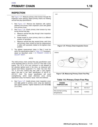
- 1. HOME PRIMARY CHAIN 1.10 INSPECTION 12047 See Figure 1-27. Measure primary chain tension through the inspection cover opening. Adjust primary chains not meeting vertical free play specifications. 1. See Figure 1-27. Remove two fasteners with captive washers and primary chain inspection cover with gasket from primary cover. 2. See Figure 1-28. Check primary chain tension by mea- suring vertical free play. a. Measure vertical free play through chain inspection cover opening. b. Rotate engine to move primary chain to a different position on sprockets. c. Measure vertical free play several times, each time with primary chain moved so that the measurement is taken with sprockets rotated to the tightest chain Figure 1-27. Primary Chain Inspection Cover position. 3. The tightest measurement taken in Step 2 must be within the specifications listed in Table 1-9. If necessary, b0085a6x adjust as described under 1.10 PRIMARY CHAIN in ADJUST- MENT. NOTE The initial primary chain vertical free play specification used at the assembly plant is 1/4-1/2 in. (6.4-12.7 mm) with a cold engine. The 1/4 in. (6.4 mm) minimum is only allowed at the absolute tightest point in the drive, as measured with special- ized factory equipment. If a chain has less than 1/4 in. (6.4 mm) vertical free play (with a cold engine), adjust free play to the “field” specification of 3/8-1/2 in. (9.5-12.7 mm). The looser specification will avoid Figure 1-28. Measuring Primary Chain Free Play overtightening, which might otherwise occur during adjustment using “non-factory” equip- ment and methods. Table 1-9. Primary Chain Free Play 4. See Figure 1-27. Install primary chain inspection cover and new gasket to primary cover using two fasteners ENGINE in. mm with captive washers. Tighten fasteners to 84-108 in-lbs TEMPERATURE (10-12 Nm). Cold 3/8-1/2 9.5-12.7 Hot (normal running 1/4-3/8 6.4-9.5 temperature) 2006 Buell Lightning: Maintenance 3 1-31
- 2. ADJUSTMENT 8403 NOTE 1 If vertical free play cannot be set within the limits specified, 2 then primary chain and/or chain adjuster are worn beyond adjustment limits. Replace parts as necessary. See 6.5 PRI- MARY CHAIN. 1. See Figure 1-29. Loosen locknut (1). 2. Turn adjusting fastener (2): a. Clockwise (inward) to reduce free play. b. Counterclockwise (outward) to increase free play. 3. Tighten locknut (1) to 20-25 ft-lbs (27-34 Nm). 1. Locknut 2. Adjusting Fastener Figure 1-29. Chain Tension Adjusting Fastener
- 3. HOME SUSPENSION DAMPING ADJUSTMENTS 1.11 GENERAL 1WARNING Do not exceed the motorcycle Gross Vehicle Weight 1WARNING Rat- ing (GVWR). Exceeding the GVWR can affect stability and handling, which could result in death or serious Before evaluating and adjusting suspension settings, injury. (00016a) check the motorcycle’s tires. Be sure tires are properly inflated, balanced and have adequate tread. Inspect your ● GVWR is the sum of the weight of the motorcycle, tires regularly and see a Buell dealer for replacements. acces- sories, and the maximum weight of the rider, Riding with excessively worn, unbalanced or under- passenger and cargo that can be safely carried. inflated tires can adversely affect stability and handling, which could result in death or serious injury. (00114a) ● The GVWR is shown on the information plate, located on the frame steering head. Make all suspension adjustments in one or two click incre- ments. Adjusting more than one or two clicks at a time may cause you to skip the best adjustment. Test ride after each Ride Quality Enhancement adjustment. When an adjustment makes no difference, return to the previous adjustment and try a different approach. The stock settings are designed to offer sufficient chassis control, but some may choose to enhance ride comfort over If both preload adjustments are correct, and you have the rougher road conditions or for long rides. Adjusting the com- rebound and compression damping set at the factory recom- pression setting will reduce both high and low speed damp- mended points, the motorcycle should handle and ride prop- ing. erly. If you wish to fine tune these settings they can be changed according to the following procedures. 1. Adjust suspension for rider weight. Refer to Table 1-10. and Table 1-11. NOTE Evaluating and changing the rebound and compression 2. Increase ride quality by reducing front and rear compres- damping is a very subjective process. Many variables affect sion damping by turning adjuster counterclockwise 1/4-1 motorcycle handling under different circumstances. turn. Approach all changes carefully and consult Table 1-10. 3. If additional ride quality is desired, reduce front preload by turning adjuster counterclockwise until an additional FINE TUNING SUSPENSION: line is visible and also reduce rear preload 1 position. BUELL MODELS 4. If maximum ride quality is desired, decrease front and rear rebound damping by turning adjusters counterclock- The settings are the best balance of handling, ride, and sta- wise by 1/4-1/2 turn. bility. Suspension can be changed to accommodate rider preferences for ride quality and handling for road conditions Enchanced Steering Quickness and load changes. the suspension requires decreasing the amount of preload. NOTES Increasing the load carried requires adding more preload. ● Do not continue to repeat the steps involved with the fol- lowing settings beyond those which are listed. ● Adjust suspension to the recommendation if possible, but never force adjusters beyond the mechanical stops. 1WARNING Do not operate motorcycle with loose, worn or damaged steering or suspension systems. Contact a Buell dealer for repairs. Loose, worn or damaged steering or suspen- sion components can adversely affect stability and han- dling, which could result in death or serious injury. (00113a) Changes in Load Changes in the load carried requires changes in the preload setting(s). Carrying less weight than was used for setting up
- 4. HOME The response to steering input (quickness) may be enhanced by adjusting the vehicles front/rear ride height. This adjust- ment effectively decreases the vehicles rake angle. This is achieved by adjusting the preload to increase front sag and reduce rear sag. 1. Adjust suspension for rider weight. Refer to Table 1-10. and Table 1-11. 2. Reduce steering effort by increasing the rear preload one position. 3. If more enhanced steering and cornering control is desired, reduce front preload by turning adjuster counter- clockwise until an additional line is visible. 4. If additional enhanced steering and cornering control is desired, increase rear compression damping by turning adjuster clockwise by 1/4-1/2 turn. 5. If maximum enhanced steering and cornering control is desired, increase front rebound damping by turning adjuster clockwise 1/4 turn.
- 5. Chassis Control/Handling Enhancement Cold Weather Riding Less Than 65° F (18° C) To provide more road surface feedback on smoother road conditions, increase compression and rebound settings. The viscosity of the suspension fluid increases as the temper- ature decreases. As the fluid viscosity increases so 1. Adjust suspension for rider weight. Refer to Table does the damping. It is recommended to compensate for the varying fluid viscosity by readjusting the damping adjuster 1-10. and Table 1-11. positions when operating outside the normal ambient 2. Increase chassis/handling control by increasing front and temperature range of 65-95° F (18-35° C). rear compression damping by turning adjuster clockwise 1. Adjust suspension for rider weight. Refer to Table by 1/2-1 1/2 turns. 1-10. and Table 1-11. 2. Reduce front and rear compression damping and 3. If maximum chassis control/handling control is desired, rebound damping by turning adjuster counterclockwise increase front and rear rebound damping by turning 1/4-1/2 turn. adjuster clockwise by 1/4-1/2 turn. Table 1-10. Recommended Suspension Settings for Rider Weight (XB9SX, XB12S) RIDER AND CARGO FRONT FORK REAR SHOCK WEIGHT PRELOAD PRELOAD LB. KG # OF *COMPRESSION *REBOUND *COMPRESSION *REBOUND POSITION LINES Less than 130 59 7 2 1.75 1 2.50 2 130-150 59-68 6.5 1.75 1.75 2 2.25 1.75 150-170 68-77 6 1.50 1.625 3 2 1.50 170-190 77-86 5.5 1.50 1.50 4 1.75 1.50 190-210 86-95 5 1.25 1.50 5 1.50 1.25 210-230 95-104 4.5 1.25 1.50 6 1.25 1 230-GVWR 104-GVWR 4 1 1.25 7 1.25 1 * Note all compression and rebound settings are number of turns out from maximum. Table 1-11. Recommended Suspension Settings for Rider Weight (XB12Scg) RIDER AND CARGO FRONT FORK REAR SHOCK WEIGHT PRELOAD PRELOAD LB. KG # OF *COMPRESSION *REBOUND *COMPRESSION *REBOUND POSITION LINES Less than 150 68 6 1.75 1.75 1 3 2 150-170 68-77 5.5 1.75 1.5 2 2.5 1.25 170-190 77-86 5 1.50 1.5 3 2.25 1.25 190-210 86-95 4.5 1.50 1.25 4 2 1 210-230 95-104 4 1.25 1.25 5 1.75 1 230-250 104-113 3.5 1.25 1 6 1.5 0.75 250-GVWR 113-GVWR 3 1 1 7 1.25 0.75 * Note all compression and rebound settings are number of turns out from maximum. 2006 Buell Lightning: Maintenance 1-35
- 6. Table 1-12. Recommended Suspension Settings for Rider Weight (XB12Ss) RIDER AND CARGO FRONT FORK REAR SHOCK WEIGHT PRELOAD PRELOAD LB. KG # OF *COMPRESSION *REBOUND *COMPRESSION *REBOUND POSITION LINES Less than Less than 140 7 2 1.75 1 2.5 2 63 140-170 63-77 7 1.75 1.75 2 2.25 1.75 170-200 77-91 7 1.75 1.75 3 2 1.5 200-230 91-104 7 1.75 1.625 4 1.75 1.5 230-260 104-118 6.50 1.50 1.50 5 1.50 1.25 260-290 118-132 6.50 1.50 1.50 6 1.25 1 290-GVWR 132-GVWR 6 1.25 1.5 7 1.125 1 * Note all compression and rebound settings are number of turns out from maximum. SUSPENSION ADJUSTMENTS 1WARNING Both forks should display the same number of alignment lines. Forks that are not properly aligned can lead to loss of control, which could result in death or serious injury. (00124a) NOTE All “turn settings” in Table 1-10. and Table 1-11. are “turns out from maximum”. That is, first gently turn adjustment screws fully clockwise (until they stop), then turn adjustment screws counterclockwise the amount specified. The recommended rebound and compression damping set- tings for various road and riding conditions are given in Table 1-10. and Table 1-11. Setting Front Fork Preload 1. Check number of lines (3) to be showing for your load condition. Refer to Table 1-10. and Table 1-11. 2. See Figure 1-30. Adjust preload by turning the adjuster nut (2) with a wrench. Setting Front Fork Rebound Damping 1. See Figure 1-30. Using a screwdriver, turn the slotted dial (1) clockwise until it stops. This is the maximum rebound damping setting. 2. Then turn the dial counterclockwise the recommended amount specified in Table 1-10. and Table 1-11. Setting Front Fork Compression Damping 1. See Figure 1-31. Using a screwdriver, turn the slotted dial clockwise until it stops. This is the maximum compression damping setting. 2. Then turn the dial counterclockwise the recommended amount specified in Table 1-10. and Table 1-11.
- 7. 9957 1 2 3 1. Rebound adjuster screw 2. Preload adjuster nut 3. Four lines visible (factory setting) Figure 1-30. Front Fork Preload And Rebound Adjuster 8361 Figure 1-31. Front Fork Compression Damping Adjuster 1
- 8. Setting Rear Shock Preload 8388 The factory setting is ramp number 2 position (ramp number 7 position being the tallest ramp and maximum preload). For recommended spring preload refer to Table 1-10. or Table 1- 11. 1. Remove seat. See 2.43 SEAT. 2. See Figure 1-32. Change the spring preload by turning the preload adjuster at the upper part of the shock with the SHOCK SPANNER WRENCH (HD-94700-52C) or the wrench included in the tool kit. b0954x1x a. Turn adjuster to setting specified in Table 1-10., Table 1-11. or Table 1-13. Rotate adjuster clockwise to increase preload. b. Rotate adjuster counterclockwise to decrease pre- load. 1WARNING A After installing seat, pull upward on front of seat to be sure it is in locked position. While riding, a loose seat can shift causing loss of control, which could result in Maximum preload adjustment (ramp number 7) death or serious injury. (00070a) Minimum preload adjustment (ramp number 1) 3. Install seat. See 2.43 Figure 1-32. Rear Shock Preload Adjuster SEAT. Setting Rear Shock Rebound Damping 8416 1. See Figure 1-33. Using a screwdriver, turn the slotted dial clockwise until it stops. This is the maximum rebound damping setting. 2. Then turn the dial counterclockwise the recommended amount specified in Table 1-10., Table 1-11. or Table 1- 13. Figure 1-33. Rear Shock Rebound Adjustment 1-36 2006 Buell Lightning: Maintenance
- 9. Setting Rear Shock Compression 10658a Damping 1. For all Lightning XB models except the Long XB12Ss, remove the seat. See 2.43 SEAT. 2. Using a screwdriver, turn the slotted dial clockwise until it stops. This is the maximum compression damping set- ting. NOTE ● See Figure 1-35. For the Lightning Long XB12Ss, the rear shock compression damping adjustor screw is accessible through the opening in the right side tail sec- tion. ● See Figure 1-34. For all other XB models, the rear shock Figure 1-34. Rear Shock Compression Damping Adjuster compression damping adjuster screw is found under the (XB9SX, XB12S, XB12Scg) seat. 3. Then turn the dial counterclockwise the recommended amount specified in Table 1-10., Table 1-11. or Table 12143 1- 13. 1WARNING A After installing seat, pull upward on front of seat to be sure it is in locked position. While riding, a loose seat can shift causing loss of control, which could result in death or serious injury. (00070a) 4. If removed, install seat. See 2.43 SEAT. Figure 1-35. Rear Shock Compression Damping Adjuster (XB12Ss)
- 10. STEERING HEAD BEARINGS 1.12 GENERAL 8421 The steering head bearings are sealed, angular contact bear- ings and do not require additional lubrication. Check steering head bearing resistance: ● At every 5000 mile (8000 km) service interval. ● When storing or removing the motorcycle for the season. INSPECTION NOTES ● Check that throttle cables do not bind when Figure 1-36. Measuring Steering Head Bearing measuring bearing resistance. Resistance ● Steering head bearings are sealed and do not require additional lubrication. DETERMINING PROPER ● Steering head bearing resistance is not adjustable. RESISTANCE Replace bearings that do not meet resistance specifica- tions. 1. Detach clutch cable at handlebar and ensure that throttle 1. Detach clutch cable at handlebar. See 1.8 CLUTCH. cables do not bind before measuring steering head bear- ing resistance. 2. Place a scissor jack under jacking point and raise front wheel off ground. For location of jacking point see 2.31 2. Remove steering stem pinch fastener at upper triple EXHAUST SYSTEM. clamp. 3. Loosen steering stem capnut and back off several turns. 1WARNING A 4. Remove lower triple clamp pinch fasteners, two per side. Steering must be smooth and free with no binding or interference. Do not operate motorcycle with loose, worn 5. Tighten steering stem capnut to 38-42 ft-lbs (52-57 Nm). or damaged steering or suspension systems. Contact a Buell dealer for repairs. Loose, worn or damaged steer- 6. Turn front wheel all the way to the ing or suspension components can adversely affect sta- right. bility and handling, which could result in death or serious injury. (00113a) 7. See Figure 1-36. Hook a spring scale into the hole in the front axle. With scale 90 degrees from fork leg, pull front 3. Check steering stem bearings for notches by turning wheel to center position. front wheel full right and then left. Repeat if necessary. 4. Next place wheel facing straight ahead and grabbing 8. The desired resistance is between 1-7 lbs (0.5-3.2 kg). both fork sides at the bottom move front-end forward and back to check for steering head play. NOTE 5. To inspect for correct steering head resistance turn front If the correct specification cannot be achieved, the steering wheel all the way to the right. head bearings must be replaced. See 2.18 STEERING HEAD BEARINGS. 6. See Figure 1-36. Hook a spring scale into the hole in the front axle. With scale 90 degrees from fork leg, pull front 9. Once correct steering head resistance has been verified, wheel to center position. apply LOCTITE 272 to steering stem pinch bolt, install a. The desired resistance to pull front wheel to center and tighten to 23-25 ft-lbs (31.1-33.8 Nm) XB9SX only. is between 1-7 lbs (0.5-3.2 kg). All other models 20-22 ft.-lbs (27-29.8 Nm). b. If steering head resistance measurement is not within specification, see DETERMINING PROPER 10. Apply LOCTITE 272 to lower triple clamp fasteners, RESISTANCE. install and tighten to 20-22 ft-lbs (27.1-29.8 Nm). 7. When adjustment is complete, attach clutch cable and 11. When adjustment is complete, attach clutch cable and adjust. See 1.8 CLUTCH. adjust. See 1.8 CLUTCH. 1-38 2006 Buell Lightning: Maintenance
- 11. 12. Remove scissor jack. 2006 Buell Lightning: Maintenance 1-39
- 12. k SPARK PLUGS 1.13 INSPECTION 4636 Check spark plugs: ● Replace every 10,000 mile (16,000 km) service interval. ● Use only Harley-Davidson 10R12A spark plugs. 1. Remove left side air scoop to access front cylinder spark plug. See 2.38 AIR SCOOPS. 2. Disconnect spark plug wire from front spark plug. 3. Using a 5/8 in. box end wrench and 5/8 in. spark plug socket, remove front spark plug. 4. Remove seat. See 2.43 SEAT. 5. Remove air cleaner assembly. See 2.37 INTAKE COVER ASSEMBLY/ 4.44 AIR CLEANER ASSEMBLY. 6. Disconnect spark plug wire from rear spark plug (use automotive spark plug boot remover/installer if required). 7. Using a 5/8 in. wobble socket and 12 in. extension, Figure 1-37. Typical Spark Plug Deposits remove rear spark plug. 8. See Figure 1-37. Compare your observations of the plug deposits with the descriptions provided below. a. A wet, black and shiny deposit on plug base, elec- trodes and ceramic insulator tip indicates an oil fouled plug. The condition may be caused by one or more of the following: worn pistons, worn piston rings, worn valves, worn valve guides, worn valve seals, a weak battery or a faulty ignition system. b. A dry, fluffy or sooty black deposit indicates an air- fuel mixture that is too rich and/or engine idling for excessive periods. c. A light brown, glassy deposit indicates an over- heated plug. This condition may be accompanied by cracks in the insulator or by erosion of the elec- trodes and is caused by an air-fuel mixture that is too lean, a hot-running engine, valves not seating or improper ignition timing. The glassy deposit on the spark plug is a conductor when hot and may cause high-speed misfiring. A plug with eroded electrodes, heavy deposits or a cracked insulator must be replaced. d. A plug with a white, yellow, tan or rusty brown pow- dery deposit indicates balanced combustion. Clean off spark plug deposits at regular intervals.
- 13. 1WARNING 1WARNING 8389 Compressed air can pierce the skin and flying debris from compressed air could cause serious eye injury. Wear safety glasses when working with compressed air. Never use your hand to check for air leaks or to deter- mine air flow rates. (00061a) 9. If the plugs require cleaning between tune-ups and replacement plugs are not available, proceed as follows: a. Degrease firing end of spark plug using ELECTRI- CAL CONTACT CLEANER. Dry plug with com- pressed air. b. Use a thin file to flatten spark plug electrodes. A spark plug with sharp edges on its electrodes Figure 1-38. Rear Spark Plug Access requires 25-40% less firing voltage than one with rounded edges. 10. If the plugs cannot be cleaned, replace with 10R12A spark plugs. 11. Check electrode gap with a wire-type feeler gauge. Gap should be 0.035 in. (0.9 mm). 12. Apply LOCTITE ANTI-SEIZE to threads of spark plugs. Install and tighten spark plugs to 12-18 ft-lbs (16- 24 Nm). NOTES ● Start threading rear spark plug with 3/8” fuel hose being careful not to cross thread spark plug. ● Start front spark plug with fingers. ● An extension may be needed to push on rear spark plug boot to ensure it is seated properly. 13. Connect spark plug wires. Verify that wires are securely connected to coil and spark plugs. See 7.4 SPARK PLUG CABLES. 14. Install left side air scoop. See 2.38 AIR SCOOPS. 15. Install air cleaner assembly. See 2.37 INTAKE COVER ASSEMBLY/4.44 AIR CLEANER ASSEMBLY. 1WARNING A After installing seat, pull upward on front of seat to be sure it is in locked position. While riding, a loose seat can shift causing loss of control, which could result in death or serious injury. (00070a) 16. Install seat. See 2.43 SEAT. 2006 Buell Lightning: Maintenance 1-41
- 14. HOME REMOVAL 12144 CAUTION Install air filter before running engine. Failure to do so can draw debris into the engine and could result in engine damage. (00207a) Check air cleaner filter element: ● Inspect at the 1000 mile (1600 km) service interval and at every 5000 mile (8000 km) service interval thereafter. ● Replace at every 20,000 mile (32,000 km) service interval. NOTES ● Inspect and replace air cleaner filter element more often if the motorcycle is run in a dusty environment. Figure 1-39. Air Intake Screen ● See Figure 1-39. Do not cover or restrict the air intake 12049 screen. Certain tank bags or accessories may cover or restrict the air intake screen. This may reduce power 6 2 1 and performance. 3 1. Remove seat. See 2.43 SEAT. 5 2. Remove four fasteners, nylon washers and intake cover assembly. See 2.37 INTAKE COVER ASSEMBLY. 4 3. See Figure 1-40. or Figure 1-42. Remove fuel vent tube (4) from vapor valve (6) at front of air cleaner cover and groove on top of air cleaner cover (1). 4. See Figure 1-43. Unlatch six latching tabs and remove air cleaner cover from baseplate. 1. Air cleaner cover 5. See Figure 1-44. Remove the filter element (1) from 2. Actuator (interactive exhaust) baseplate (2). Inspect and replace if necessary. 3. Fuel vent tube 4. Cable (interactive exhaust) 5. Harness (interactive exhaust) CAUTION 6. Vapor valve See Figure 1-44. Cover the velocity stack so nothing can Figure 1-40. Air cleaner cover, Fuel Vent Tube and Fuel drop into the motor. Vapor Valve (XB12 solid color models) CLEANING AND INSPECTION 1WARNING A Do not use gasoline or solvents to clean filter element. Flammable cleaning agents can cause an intake system fire, which could result in death or serious injury. (00101a) hoses (1) and intake air sensor (2) are captured in 1. Check filter element. Hold filter element up to strong light base- plate behind velocity stack (3). source. The element can be considered sufficiently clean if light is uniformly visible through the element. 2. Thoroughly clean baseplate and inside of air cleaner cover. 3. See Figure 1-45. Make sure two crankcase breather
- 15. HOME AIR CLEANER FILTER 1.14 Figure 1-41. Actuator Cover for XB12 Models with translucent body panel.
- 16. INSTALLATION 12134 3 1 1. See Figure 1-44. Place filter element (1) on baseplate (2). 2 2. See Figure 1-40. Position air cleaner cover (1) over baseplate. Make sure air filter remains correctly posi- tioned. 3. Install air cleaner cover by latching latch tabs to base- plate. 4. For XB12 models, verify that the actuator cable and har- ness are located in the grooves in the air cleaner cover. 1. Air cleaner cover 2. Fuel vent tube CAUTION 3. Vapor valve The vent tube is now a larger outer diameter than previ- ous and requires extra effort to install into the functional Figure 1-42. Air Cleaner Cover, Fuel Vent Tube and air cleaner assembly. Failure to properly install vent line Fuel will result in cosmetic damage to the inside of the trans- Vapor Valve (XB9SX “Translucid” model) lucent intake cover assembly. 5. Position fuel vent tube (3) in groove on top of air cleaner 12135 cover and connect to fuel vent valve (6). Secure vent tube to vent valve with new cable strap. NOTE If necessary, adjust interactive exhaust cable. See 1.16 INTERACTIVE EXHAUST CABLE (XB12 MODELS). 6. Install intake cover assembly with four fasteners and nylon washers. Tighten fasteners to 12-36 in-lbs (4- 4 Nm). Figure 1-43. Air Cleaner Cover Latches 1WARNING A After installing seat, pull upward on front of seat to be sure it is in locked position. While riding, a loose seat 11214 can shift causing loss of control, which could result in death or serious injury. (00070a) 7. Install seat. See 2.43 SEAT. 4 12145 1 3 2 3 3 2 1 1. Filter element 4. Velocity stack 2. Baseplate assembly 3. Air cleaner cover latch tabs 1-42 2006 Buell Lightning: Maintenance
- 17. 2. Intake air sensor 1. Breather hoses (2) 3. Velocity stack Figure 1-44. Installed Air Cleaner Filter Element Figure 1-45. Air Cleaner Base Plate Assembly 2006 Buell Lightning: Maintenance 1-43
- 18. HOME THROTTLE CABLE AND IDLE SPEED ADJUSTMENT 1.15 THROTTLE CABLE 6853 1WARNING A Throttle cables must not pull tight when handlebars are 5 turned fully to left or right fork stops. Be sure wires and throttle cables are clear of fork stops at steering head so 4 they will not be pinched when fork is turned against 2 stops. Steering must be smooth and free with no binding or interference. Anything interfering with steering sys- 1 tem operation may cause loss of vehicle control, which 3 could result in death or serious injury. 1. Rubber boot NOTE 2. Throttle control cable 3. Idle control cable If replacing the idle adjustment cable it will be necessary to 4. Cable adjuster apply anti-seize to the threads before installing to the throttle 5. Cable adjuster lock body assembly. Check throttle cable adjustment: Figure 1-46. Throttle Control Cables ● Before every ride. ● At every scheduled service interval. 11988 With engine running, turn handlebars through full range of travel. If engine speed changes during this maneuver, turn 1 engine OFF and adjust throttle cables as follows: 1. If removing the throttle cable, remove the air cleaner cover and baseplate. See 4.44 AIR CLEANER ASSEM- BLY. 2. Remove the left air scoop. See 2.38 AIR SCOOPS. 3. See Figure 1-46. Loosen cable adjuster lock (5) on each. 4. Turn adjusters (4) in direction which will shorten cable housings to minimum length. 2 5. Point front wheel straight ahead. Twist throttle control grip to fully open position; hold in position. 1. Idle cable routing 6. Turn adjuster on throttle control cable (2) until 2. Idle adjuster throttle cam stop touches stop plate. Tighten cable adjuster lock on throttle control cable adjuster; release Figure 1-47. Idle Adjuster throttle control grip. (scoop and frame removed for clarity) 7. Turn handlebars fully to right. Turn adjuster on idle con- trol cable (3) until end of cable housing just touches IDLE SPEED the cable guide. 8. Twist and release throttle control grip a few times. Throt- tle plate must return to idle position each time See Figure 1-47. Regular idle speed is 1050 - 1150 RPM. throttle grip is released. If this is not the case, turn Set idle speed using idle adjuster (2). Turn adjuster adjuster on idle control cable (shortening cable housing) clockwise to increase idle speed or counterclockwise to until throttle control functions properly. decrease idle speed. 9. Tighten cable adjuster lock on idle control cable. NOTE Recheck operation of throttle control. Run vehicle until engine temperature is 320 °F (160° C) then adjust idle speed to 1050 - 1150 RPM. 10. Recheck engine slow idle speed; adjust if required. 11. Install air scoop. See 2.38 AIR SCOOPS. 12. If removed, install baseplate, air cleaner, and intake cover assembly. See 4.44 AIR CLEANER ASSEMBLY.
- 19. INTERACTIVE EXHAUST CABLE (XB12 MODELS) 1.16 ADJUSTMENT NOTE For the next step in the procedure it will be necessary to obtain a permanent marker. 1. Remove four fasteners, nylon washers and intake cover assembly. See 2.37 INTAKE COVER ASSEMBLY. 5. Using a pair of pliers, fully open the exhaust valve in the NOTES muffler by pulling the cable core by the ferule that was ● The actuator cover used on models with disconnected from the cable wheel in the previous step Translucent body panels does not need to be removed until resistance is felt. Be careful not to damage the in order to adjust cable. cable core. 6. Mark the cable core with the marker all the way around ● When the ignition/light switch is turned off with the inter- where it comes out of the housing. active exhaust valve in motion, the valve will stop par- tially open which will cause an inaccurate adjustment. 7. Release the cable core and reattach the cable to the For a description of the inactive exhaust operation, cable wheel and bracket. see 8. Tighten jam nut. 7.6 INTERACTIVE EXHAUST SYSTEM (XB12 MOD- ELS). CAUTION 2. To close the valve in the muffler, cycle the actuator: Do not overtighten jam nut on interactive exhaust cable. a. Hold the throttle wide open. b. Turn the engine cut-off switch to RUN. c. Turn the ignition/light key switch 10512a ON. d. Watch the actuator cycle close/open/close. 10513 1 Figure 1-49. Checking For 1/8 in. (3.2 mm) Maximum Free Play In Either Direction For Proper Adjustment 9. See Figure 1-49. Adjust interactive exhaust cable as fol- 10512a lows: 3 a. See Figure 1-48. Move cable with your fingers from 4 side to side. There should be no more than 1/8 in. (3.2 mm) side play in cable in either direction with 1/ 2 4 in. (6.4 mm) maximum overall side play. b. Adjust cable as needed using cable adjuster (1). 1. Adjuster 2. Interactive exhaust cable 3. Jam nut 4. Cable wheel 2006 Buell Lightning: Maintenance 1 1-45
- 20. Figure 1-48. Interactive Exhaust Cable 3. See Figure 1-48. Loosen jam nut (3). 4. Remove cable (2) from bracket and cable wheel (4). 1-44 2006 Buell Lightning: Maintenance
- 21. 10514a l 1 2 1. Interactive exhaust cable 2. Frame lug Figure 1-50. Correct Cable Routing Behind Frame Lug 10. Cycle the actuator to verify cable and valve operation: 11. See Figure 1-50. Verify that the interactive exhaust a. Hold the throttle wide open. cable (1) is routed behind the frame lug (2) before b. Turn the engine cut-off switch to installing air intake cover. RUN. c. Turn the ignition/light key switch ON. CAUTION d. Watch the actuator cycle close/open/close. If cable is routed in front of the frame lug it will cause the muffler valve to stay open not allowing it to work prop- CAUTION erly. DO NOT start vehicle in this mode. 12. Install air intake cover. See 2.37 INTAKE COVER ASSEMBLY. NOTE In this mode the exhaust valve in the interactive muffler should cycle from the closed position to the wide open posi- tion and back to the closed. When the exhaust valve moves to the open position, you should see the mark on the cable core made previously. This ensures the system is working prop- erly. If you do not see the mark, verify previous cable adjust- ment.
- 22. HOME IGNITION TIMING 1.17 INSPECTION 10. If engine is coming up on the compression stroke for the REAR (incorrect) cylinder, the screen will be displaying Check ignition timing: after each removal of the cam position HIGH - 5 volts as timing mark is just coming into view at sensor. left edge of window and will switch to LOW - 0 volts at same point as the timing mark continues through the window. (If this is observed, turn flywheel forward one CHECKING STATIC revolution to bring engine to compression stroke for front TIMING cylinder.) NOTES 1CAUTION ● If timing mark check point is overshot, bump Always wear proper eye protection when drilling. Flying flywheel backwards till TDC mark is at left edge of debris may result in minor or moderate injury. inspection win- dow and repeat test bumping flywheel in forward (nor- mal) direction. CAUTION ● Never confirm timing while bumping flywheel backwards. Carefully drill hole, applying minimum pressure to drill This will give you an incorrect reading. out timer plate cover rivets. Applying too much pressure will damage cam position sensor and/or timer plate and 11. If timing is correct, install timing inspection plug and cover. tighten to 120-180 in-lbs (14-20 Nm). If timing is not cor- rect, see ADJUST TIMING in this section. NOTES ● It is not necessary to remove the spark plug to determine TDC compression stroke of the front cylinder in the fol- lowing procedure. 12146 ● Do not remove the timing inspection cover to check the static timing. If timing must be corrected, the inspection plate will then be removed. 1. Raise rear wheel using a lift or jacking point. Tie down motorcycle for additional support. 2. Remove timing inspection plug. 3. Place transmission in 5th gear. 4. Connect Digital Technician to data port on motorcycle and select the Static Timing procedure screen. 5. Turn on ignition and move handlebar stop switch to the run position. Listen for fuel pump cycling to confirm igni- tion is active. 6. Turn or gently bump the flywheel in a forward Figure 1-51. Timing Plug direction using the rear wheel. Position the flywheel TDC mark at the very left edge of the inspection hole. 7. If the engine is coming up on the compression stroke for the FRONT (correct) cylinder, the screen will be display- b1250x1x ing LOW - 0 volts with timing mark at left edge of window. 8. Gently bump flywheel forward in tiny increments. 9. See Figure 1-52. If the static timing is correct, the screen will switch to HIGH - 5 volts at the precise moment the timing mark exactly centers in the inspection window. 1-46 M 2006 Buell Lightning: Maintenance
- 23. HOME Figure 1-52. Correct Timing 2006 Buell Lightning: Maintenance 1-47
- 24. ADJUST TIMING b1247x1x 1. See Figure 1-53. Remove timing plate cover. T a. Drill rivets holding the timing plate cover. b. Using a hook, remove timing plate cover. c. Loosen timing plate fasteners. 2. See Figure 1-55. If timing is advanced (mark appears on left side of window) rotate timing plate counterclockwise. 3. Check timing. See CHECKING STATIC TIMING. 4. See Figure 1-56. If timing is retarded (mark appears on right side of window) rotate timing plate clockwise. 5. Tighten sensor plate fasteners to 15-30 in-lbs (1.7-3.4 Nm). 6. Recheck timing. Figure 1-55. Advanced Timing 12136 b1248x1x Figure 1-53. Timer Cover 8391 Figure 1-56. Retarded Timing Figure 1-54. Cam Position Sensor
- 25. HOME INSPECTION b0949x1x 1WARNING A 1WARNING Horizontal Line 29-31 in. Do not modify ignition/light switch wiring to circumvent (74-79 cm) the automatic-on headlight feature. High visibility is an important consideration for motorcycle riders. Failure to have headlight on at all times could cause an accident, resulting in death or serious injury. Check headlights for proper alignment: ● When the new owner takes delivery of the motorcycle. Position Motorcycle ● When there is a change in load (adding luggage, etc.). 25 ft (7.6 m) 1. In a location with low light, draw a horizontal line on a screen or wall that measures 29-31 in. (74-79 cm) above floor. 2. See Figure 1-57. Position motorcycle 25 ft (7.6 m) away from a screen or wall by measuring the distance from the Horizontal Line front axle to the screen/wall. 29-31 in. (74-79 cm) 3. Verify correct front and rear tire pressure. See 1.7 TIRES AND WHEELS. 4. Load vehicle with rider/passenger/cargo/accessories. Weight will compress vehicle suspension slightly. 5. Stand motorcycle upright with headlights aimed straight forward. 6. Check LOW beam (right lens) for alignment. a. See Figure 1-58. Turn ignition switch to IGN. Set handlebar headlamp switch to LOW beam position. b. Check that the correct pattern of light is a double rectangular pattern and is aligned with the horizontal line as shown in Figure 1-57. c. Adjust headlight alignment. See ADJUSTMENT which follows. 7. Check HIGH beam (left) for alignment. a. See Figure 1-58. Set handlebar headlamp switch to HIGH beam position. NOTE Low beam lamp will not stay illuminated when high beam is activated. b. Check that the correct pattern of light is a circular pattern and is centered on the horizontal line as shown in Figure 1-57. c. Adjust headlamp alignment. See ADJUSTMENT section. 2006 Buell Lightning: Maintenance 1-49
- 26. HOME HEADLIGHTS 1.18 Position Motorcycle 25 ft (7.6 m) Figure 1-57. Checking Headlight Alignment 9960 1 2 1. High beam 2. Low beam Figure 1-58. Headlamp Switch 1-48 M 2006 Buell Lightning: Maintenance
- 27. ADJUSTMENT 9949 Horizontal Alignment See Figure 1-59. Loosen fasteners on right and left side of headlight housing to adjust the horizontal alignment. Vertical Alignment See Figure 1-60. Loosen fastener on the bottom of headlight housing to adjust the vertical alignment. NOTE Only loosen headlamp alignment fasteners enough to adjust headlamp. Once headlights are aligned, tighten fasteners to 48-72 in-lbs (5-8 Nm). 9950 h Figure 1-59. Horizontal Headlamp Adjustment 9951
- 28. Figure 1-60. Vertical Headlamp Adjustment
- 29. HOME ADJUSTMENT 8390 NOTE If closed throttle TP degree reading is not between 5.1° - 6.2°, TPS should be re-calibrated. See ADJUSTMENT below. 1. Connect vehicle to Digital Technician. 2. Select calibrations screen/TPS Function. 3. Select Buell TPS zero tab. 4. Select TP volts on screen. 5. See Figure 1-61. Back off idle adjustment until TP volts stop decreasing and then continue to back out one full Figure 1-61. Idle Adjuster (behind left fork) turn. 6. Open and snap shut throttle control grip 2-3 times. NOTE This is to ensure that the throttle plate is completely closed before beginning recalibration. 7. With ignition and run switch in the on position with engine off and throttle in the closed position press the TPS zero button at the bottom of the screen. 8. Select TPS zero button and perform TPS zero. NOTE When calibration is complete, dialogue box will appear on Digital Tech screen with message display “Command Sent Successfully”. Press OK. 9. Turn idle adjustment cable screw clockwise until TPS degrees read 5.2-5.6 degrees. 10. Run vehicle until engine temperature is at 320 °F (160° C). 11. Set idle to 1050-1150 RPM. 2006 Buell Lightning: Maintenance 1 1-51
- 30. STORAGE 1.20 GENERAL REMOVAL FROM STORAGE 1WARNING 1WARNING 1WARNING Do not store motorcycle with gasoline in tank within the The clutch failing to disengage can cause loss of home or garage where open flames, pilot lights, sparks control, which could result in death or serious injury. or electric motors are present. Gasoline is extremely Prior to starting after extended periods of storage, place flammable and highly explosive, which could result in trans- mission in gear and push vehicle back and forth death or serious injury. (00003a) several times to assure proper clutch disengagement. (00075a) If the motorcycle will not be operated for several months, such as during the winter season, there are several things 1. Charge and install battery. See 1.4 BATTERY which should be done to protect parts against corrosion, to MAINTE- NANCE. preserve the battery and to prevent the buildup of gum and 2. Remove and inspect spark plugs. Replace if varnish in the fuel system. necessary. 1. Fill fuel tank and add a gasoline stabilizer. Use one of See 1.13 SPARK PLUGS. the commercially available gasoline stabilizers following 3. Inspect air filter element. Replace if necessary. See the manufacturer’s instructions. Run engine until treated 1.14 gasoline has had a chance to reach fuel injectors. AIR CLEANER FILTER. 2. Remove battery and charge as needed to maintain the 4. If fuel tank was drained, fill fuel tank with fresh gasoline. correct voltage. See 1.4 BATTERY MAINTENANCE. 5. Start the engine and run until it reaches normal operat- 3. Remove the spark plugs, inject a few squirts of engine ing temperature. Check fluids and refill to proper levels if oil into each cylinder and crank the engine 5-6 required. revolutions. Reinstall spark plugs. See 1.13 SPARK a. Check engine oil level. See 1.5 ENGINE LUBRICA- PLUGS. TION SYSTEM. 4. Adjust primary chain. See 1.10 PRIMARY CHAIN. b. Check transmission fluid level. See 1.8 CLUTCH. 5. Check tire inflation. See 1.7 TIRES AND WHEELS. If the 6. Perform all of the checks in the PRE-RIDING CHECK motorcycle will be stored for an extended period of time, LIST in the Owner’s Manual. securely support the motorcycle so that all weight is off the tires. 1WARNING Be sure that brake fluid or other lubricants do not con- tact brake pads or discs. Such contact can adversely affect braking ability, which could cause loss of control, resulting in death or serious injury. (00290a) 6. Wash and polish body panels, molded-in-color and chrome-plated surfaces. 7. If motorcycle is to be covered, use a material that will breathe, such as light canvas. Plastic materials that do not breathe promote the formation of condensation.
- 31. HOME TROUBLESHOOTING 1.21 GENERAL Starts Hard 1. Spark plugs in bad condition, have improper gap or are The following check list can be helpful in locating most oper- partially fouled. ating troubles. Refer to the appropriate sections in this Ser- vice Manual for detailed procedures. 2. Wires are crossed. 3. ATC in stuck open. 4. Spark plug cables in bad condition and shorting. ENGINE 5. Battery nearly discharged. 6. Loose wire connection at one of the battery terminals, at Starter Motor Does Not Operate or Does 19. No output from CMP sensor. See dealer. Not Turn Engine Over 20. Inoperative fuel pump. See dealer. 1. Engine stop switch in OFF position. 2. Ignition key switch not ON. 3. Discharged battery or loose or corroded connections. (Solenoid chatters.) 4. Starter control relay or solenoid not functioning. 5. Electric starter shaft pinion gear not engaging or over- running clutch slipping. 6. Clutch lever not pulled in. Vehicle in gear. 7. Starter interlock circuit malfunction. Engine Turns Over But Does Not Start NOTE See 4.11 ENGINE CRANKS BUT WILL NOT START for spe- cific tests. 1. Fuel tank empty. 2. Discharged battery, loose or broken battery terminal con- nections. 3. Fouled spark plugs. 4. Loose or shorting spark plug cables or connections. 5. Ignition timing badly out of adjustment. 6. Loose wire connection at coil or battery connection or plug between ignition sensor and module. See Section 4. 7. Ignition coil not functioning. 8. Ignition module not functioning. 9. Ignition sensor not functioning. 10. Sticking or damaged valve or valves. 11. Engine oil too heavy (winter operation). 12. Ignition circuit interlock malfunction. 13. No output from the ECM. See dealer. 14. Inadequate fuel pressure in fuel lines (possible leak). See dealer. 15. Clogged fuel filter. See dealer. 16. Clogged fuel injectors. See dealer. 17. Tripped bank angle sensor. Turn key to OFF, wait 15 sec- onds, and then back to IGN again to start bike. 18. TP Sensor/fast idle screw not set properly. See dealer. 2006 Buell Lightning: Maintenance 1-53
- 32. HOME coil or at plug between ignition sensor and module. 7. Throttle controls not adjusted correctly. 8. Ignition coil not functioning. 9. Engine oil too heavy (winter operation). 10. Ignition not timed properly. See dealer. 11. Vapor vent valve plugged or fuel line closed off restricting fuel flow. 12. Water or dirt in fuel system. 13. Air leak at intake manifold. 14. Valves sticking. 15. TP Sensor and/or fast idle screw not set properly. See dealer. 16. Oxygen, IAT or ET sensors damaged or malfunctioning. See dealer. Starts But Runs Irregularly or Misses NOTE See 4.15 MISFIRE for specific tests. 1. Spark plugs in bad condition or partially fouled. 2. Spark plug cables in bad condition and shorting. 3. Spark plug gap too close or too wide. 4. Ignition coil not functioning. 5. Ignition module not functioning. 6. Ignition sensor not functioning. 7. Battery nearly discharged. 8. Damaged wire or loose connection at battery terminals or coil. 9. Intermittent short circuit due to damaged wire insulation. 10. Water or dirt in fuel system and throttle body or filter. 11. Vapor vent valve plugged. 12. Throttle controls improperly adjusted. 13. Air leak at intake manifold or air filter. 14. Damaged intake or exhaust valve. 15. Weak or broken valve springs. 16. Incorrect valve timing. 17. Oxygen, IAT or ET sensors damaged or malfunctioning. See dealer. 18. TP Sensor not set properly. See dealer. 19. Fuel level too low. Add gasoline. 20. Inoperative fuel injector. See dealer. 21. Obstructed fuel tank vent valve or pinched vent tube. See dealer. 1-52 2006 Buell Lightning: Maintenance
- 33. Spark Plug Fouls Repeatedly 1. Incorrect spark plug. 2. Piston rings badly worn or broken. 3. Valve stem seals worn or damaged. 4. Valve guides badly worn. 5. Sensors damaged. 6. Air intake screen covered or restricted. Pre-Ignition or Detonation (Knocks or Pings) 1. Excessive carbon deposit on piston head or combustion chamber. 2. Incorrect heat range spark plug. 3. Spark plugs not firing. 4. Ignition timing advanced. 5. Fuel octane rating too low. 6. Intake manifold vacuum leak. Overheating 1. Insufficient oil supply or oil not circulating. 2. Clogged or damaged fins on oil cooler. 3. Cooling fan not operating properly. 4. Leaking valves. 5. Heavy carbon deposit. 6. Ignition timing retarded. Valve Train Noise 1. Hydraulic lifter not functioning properly. 2. Bent push rod. 3. Cam, cam gears or cam bushings worn. 4. Rocker arm binding on shaft. 5. Valve sticking in guide. Excessive Vibration 1. Engine tie-bars loose, broken or improperly spaced. 2. Isolator mounting fasteners loose. 3. Broken frame. 4. Primary chain badly worn or links tight as a result of insufficient lubrication. 5. Wheels not aligned and/or tires worn. 6. Internal engine problem. 7. Wheels not balanced correctly.
- 34. ENGINE LUBRICATION SYSTEM Oil Does Not Return To Oil Tank 1. Oil tank empty. 2. Return pump gears damaged. 3. Oil feed pump not functioning. 4. Restricted oil lines or fittings. Engine Uses Too Much Oil or Smokes Excessively 1. Piston rings badly worn or broken. 2. Valve stem seals worn or damaged. 3. Valve guides worn. Engine Leaks Oil From Cases, Push Rods, Hoses 1. Loose parts. 2. Imperfect seal at gaskets, push rod cover, washers, etc. To aid locating leaks, use BLACK LIGHT LEAK DETEC- TOR (Part No. HD-35457). 3. Restricted oil return line to tank. 4. Restricted breather passage(s) to air cleaner. ELECTRICAL SYSTEM Alternator Does Not Charge 1. Regulator-rectifier module not functioning. 2. Rectifier not grounded. 3. Engine ground wire loose or broken. 4. Loose or broken wires in charging circuit. 5. Stator not functioning. 6. Rotor not functioning. Alternator Charge Rate Is Below Normal 1. Regulator-rectifier module not functioning. 2. Stator not functioning. 3. Rotor not functioning. 4. Weak battery. 5. Loose connections. FUEL SYSTEM Poor Fuel Economy 1. Oxygen sensor damaged or malfunctioning (bike running rich). See dealer. 2. Air intake screen covered or restricted.
- 35. TRANSMISSION CHASSIS Shifts Hard Irregular/Inadequate Brake Action 1. Clutch dragging slightly. 1. Master cylinder low on fluid. 2. Shifter forks (inside transmission) damaged. 2. Brake line contains air bubbles or moisture. 3. Corners worn off shifter clutch dogs (inside transmis- 3. Master or wheel cylinder piston worn. sion). 4. Brake pads covered with grease or oil. Jumps Out of Gear 5. Brake pads badly worn to minimum lining thickness. 6. Brake rotor badly worn or warped. 1. Shifter engaging parts (inside transmission) badly worn and rounded. 7. Brake pads dragging or excessive braking (brake fades due to heat buildup). 2. Shifter forks bent. 8. Insufficient brake pedal or hand lever free play (brake 3. Damaged gears. drags). CLUTCH Handling Irregularities 1. Tires improperly inflated. See 1.7 TIRES AND WHEELS. Do not overinflate. Slips 2. Loose wheel axle. Tighten front axle to 39-41 ft-lbs (53- 1. Clutch controls improperly adjusted. 56 Nm). Tighten rear axle to 48-52 ft-lbs (65-70 Nm). 2. Worn friction plates. 3. Excessive wheel hub bearing play. 4. Rims and tires out-of-true side to side (lateral tire runout Drags or Does Not Release should not be more than 0.080 in. (2.03 mm)). 1. Clutch controls improperly adjusted. 5. Rims and tires out-of-round radially (tire runout should 2. Clutch plates excessively warped. not be more than 0.060 in. (1.5 mm)). 6. Irregular or peaked front tire tread wear. Chatters 7. Tire and wheel unbalanced or weights on wrong side of 1. Friction or steel plates worn, warped or dragging. wheel. (Front wheel weights must be on the brake rotor side.) 8. Steering head bearings improperly tightened or worn. See 1.12 STEERING HEAD BEARINGS. Check for proper torque and replace worn bearings. See 2.17 FORK CLAMPS, UPPER AND LOWER. 9. Shock absorber or front forks not functioning normally due to incorrect adjustment. See 1.11 SUSPENSION DAMPING ADJUSTMENTS. 10. Heavy front end loading. Non-standard equipment on the front end (such as heavy radio receivers, extra lighting equipment or luggage) tends to cause unstable handling. 2006 Buell Lightning: Maintenance 1-55
- 36. SUSPENSION Chattering, sliding or an uncomfortable feeling are suspen- sion-related. Handling and a swinging fork are geometry- When making adjustments, remember there are two medi- related, but often these unwanted characteristics can be ums in setting up a bike, geometry and suspension. Both solved by suspension adjustments. components work together because suspension is a part of The following tables list possible suspension and operating geometry. In order to solve handling problems, it is troubles and their probable causes. important to diagnose the problem’s true nature. Table 1-13. General Suspension Problems TROUBLESHOOTING CONDITION ADJUSTMENT SOLUTION Bike wallows through turns. Increase rebound damping. Feels loose or vague after bumps. Wheel tends to “pogo” after passing over a bump. This is noticeable by watching the bike continue to bounce as it travels over multiple bumps. Wheel responds to bump, but doesn’t return to ground quickly after bumps. This is Reduce rebound damping. more pronounced over a series of bumps and is often referred to as “packing down.” The bike bottoms out or dips while cornering. Increase compression damping. Bike has excessive brake dive. Harsh ride particularly over washboard surfaces. Reduce compression damping. Bumps kick through handlebars or seat. Suspension seems not to respond to bumps. This is evidenced by tire chattering (a movement with short stroke and high frequency) through corners or by jolting the rider over rough roads. Table 1-14. Rear Suspension Problems TROUBLESHOOTING CONDITION ADJUSTMENT SOLUTION “Pumping on the Rear” occurs when you are accelerating 1. The shock is too soft. Increase compression damping. If out of a corner. This problems occurs in two varieties. the adjuster is already set to the maximum, add more 1. The first type has a movement with a long stroke and a preload to the spring (one turn maximum). high frequency. 2. In this case the shock is too hard. Decrease compres- 2. The second version has a movement with a short stroke sion damping. and high frequency. Chattering during braking. Decrease the compression damping. If the problem persists, decrease rebound damping for a faster rebound rate. Less spring preload may also help. Lack of tire feedback. The suspension is too soft. Increase compression damping. Sliding during cornering. Sliding may occur going into the The suspension is too hard. Decrease compression damp- corner or accelerating out of the corner. ing. Table 1-15. Front Suspension Problems TROUBLESHOOTING CONDITION ADJUSTMENT SOLUTION Not absorbing bumps. A good suspension is a balance between damping and track condition. Finding this balance requires exploring all possible compression settings. Lack of tire feedback. Increase compression damping. Tire slides. Decrease compression damping.
- 37. NOTES 1-56 2006 Buell Lightning: Maintenance