SlideShare une entreprise Scribd logo
1  sur  14
Télécharger pour lire hors ligne
INSTITUTE OF PHYSICS PUBLISHING                                              PHYSICS IN MEDICINE AND BIOLOGY
Phys. Med. Biol. 49 (2004) 2015–2028                                              PII: S0031-9155(04)75549-9


The design, construction and performance of a
variable collimator for epithermal neutron capture
therapy beams
                 K J Riley1, P J Binns1, S J Ali2 and O K Harling2
                 1 Nuclear Reactor Laboratory, Massachusetts Institute of Technology,

                 138 Albany St. Cambridge, MA 02139, USA
                 2 Department of Nuclear Engineering, Massachusetts Institute of Technology,

                 138 Albany St. Cambridge, MA 02139, USA

                 Received 30 January 2004
                 Published 4 May 2004
                 Online at stacks.iop.org/PMB/49/2015
                 DOI: 10.1088/0031-9155/49/10/012

                 Abstract
                 A patient collimator for the fission converter based epithermal neutron beam
                 (FCB) at the Massachusetts Institute of Technology Research Reactor (MITR-
                 II) was built for clinical trials of boron neutron capture therapy (BNCT). A
                 design was optimized by Monte Carlo simulations of the entire beam line and
                 incorporates a modular construction for easy modifications in the future. The
                 device was formed in-house by casting a mixture of lead spheres (7.6 mm
                 diameter) in epoxy resin loaded with either 140 mg cm−3 of boron carbide or
                 210 mg cm−3 of lithium fluoride (95% enriched in 6Li). The cone shaped
                 collimator allows easy field placement anywhere on the patient and is equipped
                 with a laser indicator of central axis, beam’s eye view optics and circular
                 apertures of 80, 100, 120 and 160 mm diameter. Beam profiles and the
                 collateral dose in a half-body phantom were measured for the 160 mm field
                 using fission counters, activation foils as well as tissue equivalent (A-150) and
                 graphite walled ionization chambers. Leakage radiation through the collimator
                 contributes less than 10% to the total collateral dose up to 0.15 m beyond
                 the edge of the aperture and becomes relatively more prominent with lateral
                 displacement. The measured whole body dose equivalent of 24 ± 2 mSv per
                 Gy of therapeutic dose is comparable to doses received during conventional
                 therapy and is due principally (60–80%) to thermal neutron capture reactions
                 with boron. These findings, together with the dose distributions for the primary
                 beam, demonstrate the suitability of this patient collimator for BNCT.


1. Introduction

Modern radiotherapy uses high-energy photons having exponential depth dose distributions
and well-collimated beams with small penumbrae that are not significantly broadened in the
0031-9155/04/102015+14$30.00 © 2004 IOP Publishing Ltd Printed in the UK                               2015
2016                                                                                  K J Riley et al

patient. Applied advances in computing capability have improved the modality by exploiting
these characteristics through the placement of multiple, uniquely shaped fields that match the
tumour contours to ensure better dose conformity with the planning target volume (PTV) as
defined by the ICRU (1999). In boron neutron capture therapy (BNCT) dose conformity is
more complex since it is limited more by the preferential accumulation of boron in tumour
than the physical properties of the incident beam. The presence of boron modifies the depth
dose curve of the incident radiation with a superimposed peak dose at the location of relatively
high boron concentrations. Ideally, NCT requires a homogeneous distribution of thermal
neutrons in the PTV, which makes the diffusive nature of low-energy neutron interactions in
the patient advantageous. Thermal neutrons deposit little energy in tissue allowing the PTV
to be safely enlarged to encompass, in addition to the main tumour mass, microscopically
infiltrating tumour cells that have also absorbed boron. Precisely defining the size and shape
of the radiation flux incident upon the patient is less important for BNCT in limiting the dose
to critical normal structures near the target than the steep dose gradients that arise from the
selective uptake of boron.
     Clinical studies are proceeding in the USA to establish the maximum tolerable dose
that normal brain can withstand in undergoing BNCT (Chanana et al 1999, Busse et al 2003)
while at the same time attempting to mitigate effects of the virtually untreatable brain tumour
glioblastoma multiforme. These trials are designed to maximize tumour dose while gradually
escalating the absorbed dose to normal brain, which is prescribed as a volume average over
both hemispheres and is administered in two fractions of up to three fields. The simple
field arrangements applied in these trials are sufficient to study normal brain tolerance while
exercising the conceptual advantage of BNCT to selectively deliver dose within a single field.
     Reactor-based facilities for BNCT use fixed (usually horizontal) beam lines with a very
limited number of field sizes. Generally, a beam of epithermal neutrons is obtained from
the fission process through a series of trade-offs between intensity, purity and collimation.
Though there are advantages to a well-collimated beam, it is often impractical to attain a beam
that is nearly unidirectional as in photon therapy. Therefore, the air gap used between the
collimator and patient is typically much smaller in BNCT than in conventional radiotherapy
to help preserve beam intensity and limit exposure to other parts of the body. The positioning
restrictions inherently imposed by a fixed beam line and a small air gap influence the physical
form of the collimator which must shield the patient from undesired photons and fast neutrons
that inevitably accompany the epithermal neutrons, even in the purest of beams. This must be
achieved while ensuring that the primary beam provides a well-defined field with an acceptably
uniform intensity profile for radiotherapy.
     The fission converter based epithermal neutron facility (FCB) at the MIT Research Reactor
(MITR-II) was designed to meet the present and future needs of the Harvard–MIT research
program for clinical studies in BNCT (Harling et al 2002). The portion of the horizontal beam
line nearest the patient confines the radiation field to the PTV and shields tissues that lie outside
the primary field. Practical considerations in the design of the collimator, such as the ability
to change the size of the field and to conveniently position the patient for cranial irradiations,
are essential for the present needs. The physical design of the collimator should also allow for
easy patient positioning for other disease sites that are under investigation (Coderre et al 1997,
Pignol et al 1998) and incorporate features to assist with patient alignment such as a beam’s
eye view and a backpointing laser along the central axis of the beam. Lastly, it was considered
desirable to design a beam port that can be readily modified as needed for clinical research.
A flexible collimator design permits epithermal flux to be traded for other desirable beam
parameters (such as improved collimation or filtration) that may eventually prove useful. To
accommodate the high patient throughput that will be needed for these and other studies, the
The design, construction and performance of a variable collimator                                             2017


                  Figure 1. Plan view of the epithermal neutron beam line at the MIT fission converter facility.


approach at MIT was to adopt a modular design in which the patient collimator is assembled
from several removable components that are easily interchangeable from inside the medical
room.
     A patient collimator has been designed and constructed for use in the beam line of the
FCB (Ali 2001). The neutronic performance of the field-defining device was optimized using
an MCNP model of the entire fission converter beam line. Design studies identified lead
as a good material for the collimator walls, because it scatters many epithermal neutrons
towards the patient position that might otherwise be lost from the beam (Kiger et al 1999).
A lead collimator also provides good shielding to areas outside the PTV from photons that
are produced in the beam line. Lead, however, is an inefficient shield for epithermal neutrons
and must be used with lighter nuclei to reduce the kinetic energy of neutrons through elastic
scattering in combination with elements such as boron or lithium that absorb thermal neutrons.
After identifying the best composition for the wall materials, the geometry was optimized to
offer the greatest convenience in terms of patient positioning. Attention was given to ease of
manufacture throughout the design as the device was to be constructed in-house from readily
available materials without the need for special tools or machining. After construction, the
collimator was evaluated in situ through a series of measurements performed under clinically
relevant irradiation conditions to ensure that the collimator walls provide sufficient shielding
and that the resulting epithermal neutron beam is uniform and well defined.


2. Methods and materials

2.1. Epithermal neutron beam
The FCB delivers a high-intensity beam of epithermal neutrons to the patient from a source
of fission neutrons generated in the uranium fuel of the converter. The converter is driven
by thermal neutrons from the reflector region surrounding the core of the MITR-II, which
currently operates at a maximum of 5 MW. The present configuration of the FCB is
shown in figure 1 and yields an epithermal flux at the patient position of approximately
2018                                                                                 K J Riley et al

5 × 10⁹ n cm−2 s−1 (Riley et al 2003). The fission source in the converter is moderated
and filtered with aluminium, fluorine, cadmium and lead, resulting in a beam of epithermal
neutrons that is virtually free of unwanted contamination from photons as well as fast and
thermal neutrons. The filtered beam then enters a tapered portion of the horizontal beam line
extending 1.1 m with lead walls that reflect some of the source neutrons (that might otherwise
leave the beam) towards the patient and forms a beam collimator. The 40 cm long patient
collimator extends this circular cone beyond the shielded beam line into the medical room to
provide a beam that is spatially and directionally well defined.

2.2. Computational methods
The beam line of the MIT FCB was modelled in detail using the general purpose Monte
Carlo transport code MCNP (Kiger et al 1999, Riley 2001, Riley et al 2003). Fast neutron
and photon absorbed dose rates (Dfn and Dγ , respectively), epithermal (1 eV–10 keV) neutron
flux (φ epi) and the epithermal neutron current to flux ratio (J/φ epi) were calculated in-air at
the patient position for collimators of different compositions. A homogeneous mixture of
lead and epoxy was assumed for the collimator wall. Flux tallies were convolved with photon
and neutron kerma coefficients (ICRU 2000) to determine the absorbed dose to soft muscle
tissue. Absorbed dose rates at the end of the patient collimator with circular apertures ranging
in diameter from 80 to 160 mm were calculated as a function of radial displacement from
the central axis of the beam. The full width at half maximum (FWHM) of this cross plane
profile was defined as a figure of merit to compare the effectiveness of the different collimator
designs. Circular symmetry for the beam profile was assumed and dose rates were tallied in
concentric rings with increasing diameters of 20 mm, which were chosen to match the length
of the active volume of the detector used for measurements.
      To simulate the dose to the patient in areas outside the target volume, a neutron and photon
source was written to a 1.8 × 1.4 m2 plane coincident with the end of the patient collimator
and transported into a half-body phantom. Calculations used the phantom shown in figure 2
suspended free in-air that comprises of a water filled ellipsoid with major axes of 160, 170
and 200 mm that simulated the head while water filled cylinders of diameter 120 and 360 mm
simulated the neck and torso, respectively. The 160 mm axis of the ellipsoid was coincident
with the central axis of the beam and no air gap was left between the apex of the ellipsoid and
the end plane of the collimator. The neutron and photon absorbed dose rates were averaged
over the entire volume of the head and each of the 11 body segments shown in figure 2 to
obtain sufficient statistical precision in the dose tallies. The physical absorbed dose rates
tallied in the half-body phantom included the effects of leakage radiation from both the walls
of the collimator and the beam line shielding in addition to the radiation scattered from the
primary beam.

2.3. Construction method and materials
From the Monte Carlo calculations a conical collimator extending 0.40 m into the medical room
was designed that can readily provide the required circular apertures by attaching truncated
conical pieces to its base. A modular design was chosen so that the field-defining aperture
could be changed as needed to provide differently sized or shaped apertures by only needing
to manufacture an appropriately dimensioned addition to mate with the collimator base. More
importantly, this collimator is conveniently accessible from inside the medical room and can be
easily changed to give different fields for a particular treatment plan. The collimator can also
be more extensively modified if clinical experience dictates improvements in beam delivery.
The design, construction and performance of a variable collimator                                             2019


                  Figure 2. Schematic plan view of the conical patient collimator with the 160 mm diameter aperture
                  and the water filled half-body phantom used in MCNP calculations of the collateral dose to the
                  patient. The head is an ellipsoid with major axes of 160, 170 and 200 mm, while the neck and
                  torso comprises cylinders with diameters of 120 and 360 mm, respectively.


     The patient collimator mounts on a reinforced steel structure within the medical room wall
containing an integrated annulus of lead with four fission counters that monitor the neutron
fluence delivered to the patient. The collimator itself is fabricated on a steel plate with a
concentric circular cut-out and fixtures to hoist and mount the whole assembly (Ali 2001).
The steel plate was made to accept a wooden male mould and a rolled sheet of aluminium
as a female mould to form the conical inner and outer surfaces of the collimator. The mould
was filled with a mixture containing the desired proportions of neutron and photon shielding
material. The patient collimator comprises two main segments, which form the 160 mm
diameter aperture that is shown in figure 2. Smaller apertures are formed by either extending
the length of the collimator with additional conical pieces or by replacing the end cone with
one containing the desired aperture. The various pieces mount to each other by bolting into
threaded anchors cast into the collimator.
     The collimator walls are made of lead spheres cast in an epoxy resin loaded with either
boron carbide or lithium fluoride (95% enriched in 6Li) to obtain the desired shielding
properties. A mixture of 60% lead and 40% epoxy (which yielded the smallest combined
penumbra for photons and neutrons) is easily obtained as higher volume fractions of lead
can be realized by adding different sized spheres. Lead spheres (99.99% pure) of 7.6 mm in
diameter were arranged in the mould before adding epoxy uniformly loaded with boron carbide
(10B loading of 22 mg cm−3). The mould was filled in successive layers of approximately
50 mm thickness that were allowed to cure before filling the next to ensure that the epoxy
adequately filled the interstitial spaces.
2020                                                                               K J Riley et al

     Several test pieces with various volume fractions of lead and different amounts of boron
carbide or lithium fluoride were poured to ensure an absence of voids and that sufficient
structural integrity had been attained. Volume fractions of lead ranging from 50 to 70% had
enough strength to support the weight of the collimator. Sufficient neutron attenuation was
afforded by loadings of either 140 mg cm−3 boron carbide (19.9% 10B isotopic abundance,
grain size 20–120 µm) or 210 mg cm−3 lithium fluoride, which was enriched with 95% 6Li.


2.4. Measurement methods
Horizontal and vertical cross plane profiles of the neutron flux were measured across the
constructed collimator using a cylindrical fission counter with an active volume of length
20 mm and 5 mm in diameter (LND model 30571). The pulses from fission events were
of sufficient magnitude to allow discrimination against the photon background in the beam.
Though fission counters are most sensitive to thermal neutrons, the cadmium filter in the
beam line reduces the thermal flux to such comparatively low levels that 85% of the registered
events in the fission chamber are due to epithermal neutrons (Wilson 2001). A graphite
walled ionization chamber with an active volume of 0.1 ml flushed with 99.995% pure CO2 at
20 ml min−1 was used to obtain profiles of the photon absorbed dose rate. This chamber is
operated at a bias of +250 V and has virtually no response to neutrons (Riley et al 2003).
The fission counter and ionization chamber were separately scanned across the aperture and
through the beam using a computer controlled stepper motor remotely operated from outside
the medical room. The output of each measurement is normalized to a common beam intensity
using one of the four beam monitoring detectors located at the base of the collimator.
     Measurements of the total absorbed dose rate were performed in-air and in a half-body
phantom (ART Alderson/Rando Phantom—Radiation Support Devices, Long Beach, CA)
using methods described previously (Rogus et al 1994, Riley et al 2003). The phantom is
similar in size to the water phantom used for calculations and comprised 23 layers, each
25.4 mm thick that are constructed of plastic specially formulated to simulate radiation
transport through the human body. The phantom was positioned for a lateral irradiation
with the brain centred in the 160 mm field, without an air gap. Gold foils (25 mm2 and
0.05 mm thick) with and without cadmium covers (0.5 mm thick) were placed on the midline
of several slices to determine the thermal neutron flux that was used to calculate the absorbed
dose induced by thermal neutrons captured in 14N and 10B for different displacements from the
central axis of the beam. The graphite walled ionization chamber described earlier was used
together with a tissue equivalent (A-150) plastic walled chamber flushed with methane-based
tissue equivalent gas (64.4% CH4, 32.4% CO2 and 3.2% N2). Measurements with these two
chambers are used to separate the photon and neutron absorbed dose components in the mixed
field. The portion of the neutron absorbed dose due to 14N(n,p)14C events can be subtracted
using the activation foil results, to determine the fast neutron absorbed dose that arises from
scattering with hydrogen nuclei. During these measurements one slice of the phantom was
replaced with a dummy piece machined of nylon (type 6) to the same size and containing a
7.5 mm diameter hole into which the ionization chambers were inserted.
     The dose equivalent at each measurement location was determined by applying radiation
weighting factors of 10 and 1 for neutrons and photons respectively (ICRP 1990). The
nitrogen content of brain is taken as 2.2% by weight, while 3.5% is assumed for all other
tissues (ICRU 1989). The dose equivalent from neutron capture in boron is estimated using
a boron concentration of 15 µg g−1 for all tissues in the absence of detailed information
regarding the uptake of boron in organs other than the brain. A radiation weighting factor of
20 is applied for the densely ionizing products of the boron reaction (ICRP 1990). The dose
The design, construction and performance of a variable collimator                                              2021


                  Figure 3. FWHM of the spatial profile for the neutron and photon absorbed dose rates as a function
                  of the fractional percentage volume of epoxy in the collimator wall. The field aperture used in this
                  design study has a nominal diameter of 150 mm.


equivalent is reported per unit of weighted tumour dose, which uses weighting factors of 1.0
for photons and 3.2 for neutrons. Parameters representative of the capture compound currently
in use, boronated phenylalanine (BPA), were chosen with an assumed boron concentration in
tumour of 52.5 µg g−1, and an associated RBE of 3.8 (Coderre et al 1993).


3. Results

3.1. Design studies
To determine the optimum volume fraction of epoxy and lead, the spatial profiles of the
photon and neutron absorbed dose rates were tallied for various mixtures using a collimator
with a nominal diameter of 150 mm. The FWHM for each profile was determined from an
interpolation of a least-squares fit to the tallied profile. Figure 3 plots the FWHM versus
volume fraction of epoxy mixed with lead in the collimator. The uncertainties shown in
figure 3 are derived from the error associated with a linear fit to the data at the edge of the
beam profile between 20% and 80% of full beam intensity. Each collimator also included
22 mg cm−3 of 10B. The FWHMs for both the neutron and photon profiles appear to reach
a minimum for an epoxy volume fraction of 30–45% and are unaffected by variations in the
relative compositions in this range.
     Spatial profiles and beam characteristics were calculated for fields with diameters of 80
and 100 mm that were formed by extending the length of the collimator without changing the
taper angle. These profiles are compared to those obtained by keeping the collimator length
constant and changing the taper angle on the inner surface of the piece nearest the patient to
obtain the desired diameter. The results from these calculations with their associated statistical
uncertainties are summarized in table 1. The term ‘extended’ is used to describe that the taper
angle is kept constant and the length of the collimator is altered to produce the desired field
size, while ‘fixed’ is used when the collimator length is kept constant and the taper angle is
altered to achieve the same final aperture size as illustrated in figure 4. The two collimators of
fixed length provide the same nominal intensity within the predicted (1σ ) uncertainties, while
the epithermal flux at the patient position is reduced 30–40% for the longer collimators due
2022                                                                                                K J Riley et al


               Figure 4. Schematic illustrating the ‘extended’ and ‘fixed’ approaches to forming apertures
               smaller than 160 mm diameter.


               Table 1. Calculated beam characteristics for 80 and 100 mm diameter apertures formed using the
               two different approaches illustrated in figure 4. Extended collimators are made by lengthening the
               cone to achieve the desired aperture diameter. Fixed collimators use a different taper for the inner
               cone near the patient to achieve the desired aperture diameter without changing the length of the
               beam line.
               Diameter (mm)                80 (fixed)       80 (extended)     100 (fixed)      100 (extended)

                   (109
               φ epi      cm−2 s−1)
                          n                  5.4 ± 0.2       3.2 ± 0.1         5.1 ± 0.2       3.6 ± 0.1
               J/φ                          0.80 ± 0.02     0.85 ± 0.02       0.81 ± 0.02     0.84 ± 0.02
               Dfn/φ epi (10−13 Gy cm2)     0.93 ± 0.05     1.03 ± 0.05       0.95 ± 0.05     1.02 ± 0.05
               Dγ /φ epi (10−13 Gy cm2)      2.6 ± 0.2       2.9 ± 0.2         2.9 ± 0.2       3.0 ± 0.2
               Neutron FWHM (mm)             121 ± 3          91 ± 2           132 ± 3        120 ± 3
               Photon FWHM (mm)              125 ± 3          94 ± 2           131 ± 3        122 ± 3


to greater geometric attenuation of the beam. The taper angle used for the fixed collimators,
however, scatters more of the beam resulting in slightly poorer directionality (J/φ decreases
between 3.5% and 6%) and profiles that have penumbrae 10–32% wider than the extended
version. Beam purity measured by the specific fast neutron and photon dose rates (Dfn/φ and
Dγ /φ) is largely unaffected by the different designs.
     The effect of the photons produced in the 10B(n,α)7Li capture reaction was studied by
replacing the boron in the section of the collimator nearest the patient with a similar quantity
of lithium to provide equivalent neutron absorption. A reduction in the specific photon dose
rate from 2.8 ± 0.2 to 2.2 ± 0.2 × 10⁻¹³ Gy cm2 was calculated if 50 mg cm−3 of 6Li is used
instead of 22 mg cm−3 10B for a nominal field size of 150 mm. Further simulations indicated
that the same reduction could be achieved by using lithium in only a 38 mm thick layer along
the inner surface of the collimator, as shown in figure 2.
The design, construction and performance of a variable collimator                                             2023


                  Figure 5. Total (neutron and photon) physical absorbed dose rate measured and calculated under
                  simulated therapy conditions for a lateral irradiation in the 160 mm field. The leakage radiation
                  represented by in-air absorbed dose rates (measured and calculated) is shown for comparison. The
                  data do not include the dose deposited from capture events in boron and no dose weighting factors
                  are applied.


3.2. Completed collimator

The overall physical form of the collimator was chosen based on the desire to minimize leakage
radiation to portions of the body outside the target volume but with exterior dimensions that
allow the desired fields to be conveniently arranged with the fixed beam geometry. Shielding
considerations necessitated an outer diameter at the base of the collimator that is large enough
to shadow the outer diameter of the lead collimator further upstream in the beam line. The taper
angle of the outer cone was then chosen to provide ample clearance around the collimator for
positioning the patient while retaining sufficiently thick shielding in the walls of the collimator,
for the smallest field sizes.
     The collimator was constructed using 7.6 mm diameter lead spheres that yielded a 40%
volume fraction of epoxy, based on density measurements from the test pieces. A stepped
cylindrical access port that penetrates the wall of the cone near its base was formed by casting
an acrylic tube inside the mould.


3.3. Calculated and measured performance

The total physical absorbed dose rates from neutrons and photons measured in the ART
phantom and calculated in water for a lateral irradiation are shown in figure 5 as a function of
displacement from the centre of the 160 mm field. Calculations and measurements of the in-air
absorbed dose rate obtained with no phantom present are representative of leakage radiation
from the beam line and are included in figure 5 for comparison. At any point outside the main
beam, neutrons account for no more than 10% of the total absorbed dose from either leakage
or scattered radiation. To compare the relative magnitude of radiation leaking from the beam
line with that from the primary field, which is scattered within the patient, biological weighting
factors were not applied nor was the dose from capture events in boron included. The overall
estimated uncertainty for the measurements was 7% and the statistical uncertainties for the
calculations range from 2% in the field to a maximum of 10% for the points furthest from the
beam centreline. These are omitted from figure 5 for clarity.
2024                                                                                             K J Riley et al


               Figure 6. In-air measurements of photon and epithermal neutron intensities along the central axis
               of the beam normalized to unity at the patient position for the 160 mm diameter aperture.


     Good agreement between the measured and calculated quantities is observed in-phantom
even though the size of the detector is small (0.1 ml) compared to the large tally volumes
(0.5–5 l) that were required. Relative to values measured in-air on the central axis of the beam,
dose rates outside the collimator opening are reduced to approximately one-third and 10%
at displacements of 3 and 15 cm from the edge of the aperture, respectively. The calculated
in-air dose profile shows a much steeper gradient, falling to 10% at 35 mm outside the main
beam which is significantly lower than the corresponding measurements. This discrepancy is
believed to be due in part to the presence of albedo neutrons from the walls, ceiling and floor
of the medical room that are missing from the computational model.
     The relative intensities of the epithermal neutrons and photons along the central axis of
the beam from the base of the collimator to 0.2 m beyond the exit plane of the 160 mm
diameter aperture are shown in figure 6. Each profile is normalized to unity at the end of the
collimator at the patient position. The intensities of both the photons and epithermal neutrons
decrease rapidly along the collimator axis at a rate of approximately 0.7% mm−1 near the
patient position. Statistical uncertainties of 1 and 2% associated with the measurements
and calculations are smaller than the symbols in the figure. The measurements represent an
average over the 20 mm active length of the detector that was oriented along the beam axis and
The design, construction and performance of a variable collimator                                           2025

                  Table 2. The dose equivalent per RBE weighted tumour Gy measured along the midline of the half-
                  body phantom at different displacements from the central axis for the 160 mm diameter aperture.
                  Dose equivalent was determined with weighting factors of 1, 10 and 20 for photons, neutrons and
                  the high LET boron reaction products, respectively. A boron concentration of 15 µg g−1 was
                  assumed for normal tissue. Therapeutic dose is determined using RBEs of 1.0 for photons and
                  3.2 for neutrons. A boron concentration of 52.5 µg g−1 is assumed for tumour with an associated
                  RBE of 3.8.
                  Displacement                         Dose equivalent per
                  from central     Anatomical          RBE weighted tumour
                  axis (m)         region              dose (mSv Gy−1)
                  0.21             Upper lungs           66 ± 5
                  0.32             Centre of lungs       19 ± 1.3
                  0.45             Upper intestines     6.4 ± 0.4
                  1.15             Feet                 2.4 ± 0.2


positioned with an absolute uncertainty of 5 mm. The relative location of each measurement is,
however, accurate to within 1 mm. Reasonable agreement is observed between the predictions
and the measured profiles with the exception of the photon dose rates outside the field aperture
where the measurements show a steeper attenuation.
     The measured dose equivalent at four different locations along the midline of the half-
body phantom is summarized in table 2 and is expressed per RBE weighted Gy of tumour dose
delivered at the midline of the phantom during a simulated patient irradiation. The tabulated
results for the 160 mm field correlate the measurement positions with the anatomical features
in these locations. The estimated uncertainty of 7% for these measurements is due principally
to counting statistics of the gold foil activities used to determine the absorbed dose from
neutron capture in nitrogen and boron (Riley et al 2003). A whole body dose equivalent of
24 ± 2 mSv per Gy of RBE weighted tumour dose was determined from a volume-weighted
sum of the dose equivalents calculated in the neck and torso segments of the phantom.

3.4. Patient positioning
The required beam entry point for any treatment field can be conveniently aligned with the
central axis of the beam using a vertically mounted laser that is directed along the central axis
of the collimator. The mirrors for reflecting the laser are contained in a tube that fits into the
cylindrical access port in the collimator wall and includes optics that provide a beam’s eye
view for aligning the patient in the fixed beam which would otherwise be difficult with little
or no air gap. The laser and viewing system assembly are removed for an irradiation and
replaced with a plug that was constructed separately in a manner similar to the collimator.
When the plug is removed (and the laser installed), an interlock in the beam control system
prevents an irradiation from commencing. Fiducial marks on the back wall of the medical
room and on an insert for each aperture verify proper alignment of the laser with the geometric
centre of the beam line when it is replaced. A photograph of the completed collimator and the
laser/viewing optics are shown in figure 7.
     The length of the collimator for the 160 mm field extends 0.32 m from the wall of the
medical room and is 0.31 m wide at its end, gradually increasing to 0.66 m at the wall. This
geometry is well suited to brain irradiations since most patients are positioned supine on
the treatment couch perpendicular to the beam, which does not interfere with the collimator.
Smaller field sizes provide an even more favourable geometry as the collimator is lengthened
with a thinner wall at the field aperture. The centreline of the beam in the medical room is
0.42 m above the floor and is at a comfortable height for medical staff to conduct patient
2026                                                                                                 K J Riley et al


               Figure 7. Left: photograph of the collimator mounted inside the FCB medical room with the
               120 mm diameter aperture. Right: the laser and optical system are removed from the collimator
               following patient positioning prior to commencing irradiation. A cross laser is projected along the
               central axis of the beam when the laser and optics are installed for patient set-up that also allow a
               beam’s eye view along the central axis.


set-up. The height of the beam also allows the possibility of seating the patient in a low chair,
with the head reclined into the beam. Positioning for other potential tumour sites such as the
torso, limbs and pelvis is also straightforward with this patient collimator.

4. Discussion and summary

The design of the patient collimator for the FCB achieves a practical minimum in the increase
of the FWHM for both the photon and neutron absorbed dose profiles relative to the geometric
aperture size. Replacing a portion of the boron in the collimator with lithium proved effective
in reducing the photon contamination produced by neutron capture in the collimator. Smaller
apertures formed by adding sections to the end of the collimator have superior spatial profiles
but reduced beam intensity by up to 40% compared with those provided by leaving the
length of the collimator fixed and changing the taper of the inner surface. Even using the
80 mm diameter aperture with the lowest available intensity, irradiation times comparable to
conventional radiotherapy can be achieved with the FCB (<20 min) for a peak dose in brain
tissue of 12.5 (RBE) Gy, using BPA infused at 350 mg kg−1. An advantage of the additional
space afforded by extending the collimator to form smaller apertures is to provide greater
flexibility for patient positioning.
     The patient collimator was constructed from lead and epoxy with either boron carbide
or lithium fluoride (95% enriched in 6Li), which (with the exception of enriched lithium)
are inexpensive and readily available materials. The present configuration has a removable
end segment that can be easily redesigned and constructed to provide an aperture of any size
or shape. In addition, the present collimator can be moved forward several centimetres to
allow, for example, the inclusion of a lithium (enriched in 6Li) filter that is now planned. The
detectors that serve as beam monitors are positioned upstream of these variable components
to maintain continuity in the measured output for all therapy field configurations.
     The shape of the final collimator and the axial laser that indicates the central axis of
the beam and which can be viewed even when the beam aperture is covered makes patient
The design, construction and performance of a variable collimator                                             2027

positioning easier for any irradiation site. Beam intensity at the patient position steadily
reduces with increasing distance from the end of the collimator. The distance from the end of
the collimator to the beam entry point on the surface of the patient is reproducible to within
1 mm and contributes an uncertainty of less than 1% in the fluence delivered to the patient.
     The MCNP model of the fission converter beam line proved a valuable tool for performing
the parametric studies necessary to design the patient collimator. Satisfactory agreement is
obtained between the absorbed dose rates measured outside the beam aperture and those
calculated using MCNP. Similar agreement is observed for the relative epithermal neutron and
photon intensities along the central axis of the beam.
     Leakage radiation through the walls of the collimator or from the beam line itself is only a
small fraction of the dose received in regions outside the target volume. Within 0.15 m beyond
the geometric edge of the aperture, the absorbed dose from leakage radiation contributes less
than 10% of the total collateral dose to the patient. At displacements greater than 0.3 m from
the central axis of the beam where the total dose equivalent is relatively low, leakage radiation
becomes comparable to that from scatter within the patient. Further reduction of the beam
leakage component will not significantly decrease the collateral dose received during therapy
that mostly comes from scattering of the beam within the primary target volume.
     The highest dose equivalent measured was 66 mSv per therapy (RBE weighted) Gy at a
position of 0.21 m from the central axis which is considerably greater than the 10 mSv Gy−1
reported near the edge of a 10 × 10 cm2 field for photon therapy (ICRP 1985). However,
the average measured whole body dose of 24 mSv per (RBE) Gy to tumour is similar
to the 20 mSv Gy−1 for the largest fields in photon therapy (Nath et al 1984) and less than
the 37–70 mSv Gy−1 (Followill et al 1997) for advanced tomotherapy. In BPA-mediated
BNCT, boron interactions produce between 60% and 80% of the total dose equivalent at all
locations observed outside the field and occur principally with neutrons that are scattered
from the primary beam. The relatively high dose equivalent attributed to the capture products
released from boron makes these results very sensitive to the dose weighting factors and uptake
parameters assumed.
     The simple construction technique and inexpensive materials employed have proved
successful in building collimators that provide both desirable beam characteristics and effective
patient shielding for epithermal neutron beams. The patient collimator as described in its
initial configuration has already been used successfully for clinical brain irradiations at the
MIT fission converter beam. Versatility in the design and ease of construction readily facilitate
adaptation of this collimator to satisfy the needs of further clinical studies that are envisioned
for BNCT.


Acknowledgments

The authors acknowledge the input of Dr Paul Busse, Jody Kaplan RN BSN, Dr Stead Kiger
and Dr Robert Zamenhof in the design of the collimator. This work was supported by the US
Department of Energy under contract number DEFG02-96ER62193.


References

Ali J 2001 The design optimization and construction of a patient collimator for the fission converter beam SM Thesis
      (Cambridge, MA: Massachusetts Institute of Technology)
Busse P M et al 2003 A critical examination of the results from the Harvard–MIT NCT program phase I clinical trial
      of neutron capture therapy for intracranial disease J. Neurooncol. 62 111–21
2028                                                                                                  K J Riley et al

Chanana A D et al 1999 Boron neutron capture therapy for glioblastoma multiforme: interim results from the phase
     I/II dose-escalation studies Neurosurgery 44 1182–93
Coderre J A, Capala J, Makar M and Diaz A Z 1997 Application of BNCT to other types of tumors Advances in
     Neutron Capture Therapy vol II, ed J C B Larsson and R Weinreich (Elsevier: Amsterdam) pp 649–53
Coderre J A, Makar M S, Micca P L, Nawrocky M M, Liu H B, Joel D D, Slatkin D N and Amols H I 1993
     Derivations of relative biological effectiveness for the high-LET radiations produced during boron neutron
     capture irradiations of the 9L rat gliosarcoma in-vitro and in-vivo Int. J. Radiat. Oncol. Biol. Phys. 27 1121–9
Followill D, Geis P and Boyer A 1997 Estimates of whole body dose equivalent produced by beam intensity modulated
     conformal therapy Int. J. Radiat. Oncol. Biol. Phys. 38 667–72
ICRP 1985 Protection of the Patient in Radiation Therapy ICRP Publication 44 (Oxford: Pergamon)
ICRP 1990 Recommendations of the International Commission on Radiological Protection ICRP Publication 60
     (Oxford: Pergamon)
ICRU 1989 Tissue Substitutes in Radiation Dosimetry and Measurement ICRU Report 44 (Bethesda, MA: ICRU)
ICRU 1999 Prescribing, Recording and Reporting Photon Beam Therapy (Supplement to ICRU Report 50) ICRU
     Report 62 (Bethesda, MD: ICRU)
ICRU 2000 Nuclear Data for Neutron and Proton Radiotherapy and for Radiation Protection ICRU Report 63
     (Bethesda, MD: ICRU)
Kiger W S III, Sakamoto S and Harling O K 1999 Neutronic design of a fission converter-based epithermal neutron
     beam for neutron capture therapy Nucl. Sci. Eng. 131 1–22
Harling O K and Riley K J 2002 A critical assessment of BNCT beams from fission reactors Research and Development
     in Neutron Capture Therapy ed W Sauerwein, R Moss and A Wittig (Monduzzi: Bologna) pp 159–62
Harling O K et al 2002 The fission converter-based epithermal neutron irradiation facility at the Massachusetts
     Institute of Technology Reactor Nucl. Sci. Eng. 140 223–40
Nath R, Epp E R, Laughlin J S, Swanson W P and Bond V P 1984 Neutrons from high-energy x-ray medical
     accelerators: an estimate of risk to the radiotherapy patient Med. Phys. 11 231–41
Pignol J P, Oudard H, Chauvel P, Sauerwein W, Gabel D and Prevot G 1998 Selective delivery of 10B to soft tissue
     sarcoma using 10B-L-borophenylalanine for boron neutron capture therapy Br. J. Radiol. 71 320–3
Riley K J 2001 Construction and characterization of a fission converter based epithermal neutron beam for BNCT
     PhD Thesis (Cambridge, MA: Massachusetts Institute of Technology)
Riley K J, Binns P J and Harling O K 2003 Performance characteristics of the MIT fission converter based epithermal
     neutron beam Phys. Med. Biol. 48 943–58
Rogus R D, Harling O K and Yanch J C 1994 Mixed field dosimetry of neutron beams for boron neutron capture
     therapy at the MITR-II research reactor Med. Phys. 21 1611–25
Wilson B A 2001 Automatic control and monitoring of the MIT fission converter beam SM Thesis (Cambridge, MA:
     Massachusetts Institute of Technology)

Contenu connexe

Tendances

Magnetic nanoparticles applications and bioavailability for cancer therapy
Magnetic nanoparticles applications and bioavailability for cancer therapyMagnetic nanoparticles applications and bioavailability for cancer therapy
Magnetic nanoparticles applications and bioavailability for cancer therapyPravin Chinchole
 
Biomaterials for photonics
Biomaterials for photonicsBiomaterials for photonics
Biomaterials for photonicsudhay roopavath
 
Boron Chemistry And Applications To Cancer Treatment.pdf
Boron Chemistry And Applications To Cancer Treatment.pdfBoron Chemistry And Applications To Cancer Treatment.pdf
Boron Chemistry And Applications To Cancer Treatment.pdfMarcPerry16
 
Biomedical Application of Magnetic Nanomaterials
Biomedical Application of Magnetic NanomaterialsBiomedical Application of Magnetic Nanomaterials
Biomedical Application of Magnetic NanomaterialsMahmudun Nabi
 
Abubakar musa seminar updated 3
Abubakar musa seminar updated 3Abubakar musa seminar updated 3
Abubakar musa seminar updated 3ABUBAKAR MUSA
 
APPLICATION OF BORON IN CANCER TREATMENT
APPLICATION OF BORON IN CANCER TREATMENTAPPLICATION OF BORON IN CANCER TREATMENT
APPLICATION OF BORON IN CANCER TREATMENTMuhammad Mudassir
 
CNT in Nanomedicine
CNT in NanomedicineCNT in Nanomedicine
CNT in Nanomedicinebabudx
 
GFP Super resolution microscopy
GFP Super resolution microscopyGFP Super resolution microscopy
GFP Super resolution microscopyDr. Andrea Nestl
 
nanotechnology in drug delivery and diagnostic
nanotechnology in drug delivery and diagnostic nanotechnology in drug delivery and diagnostic
nanotechnology in drug delivery and diagnostic Saurabh Sharma
 
3D Imaging of Nanoparticles
3D Imaging of Nanoparticles3D Imaging of Nanoparticles
3D Imaging of NanoparticlesYilbert Giménez
 
magnetic nano particles in bio medical applications
magnetic nano particles in bio medical applicationsmagnetic nano particles in bio medical applications
magnetic nano particles in bio medical applicationshassan7777777
 
Magnetic nanoliposomes for combined hyperthermia and drug delivery
Magnetic nanoliposomes for combined hyperthermia and drug deliveryMagnetic nanoliposomes for combined hyperthermia and drug delivery
Magnetic nanoliposomes for combined hyperthermia and drug deliveryPriyank Kulshrestha
 
Reflectivity and Braggs Wavelength in FBG
Reflectivity and Braggs Wavelength in FBGReflectivity and Braggs Wavelength in FBG
Reflectivity and Braggs Wavelength in FBGCSCJournals
 
Biomedical applications of quantum dots
Biomedical applications of quantum dotsBiomedical applications of quantum dots
Biomedical applications of quantum dotsANJUNITHIKURUP
 
Real World Applications Pertaining the Analysis of Fiber Optic Sensors and Bi...
Real World Applications Pertaining the Analysis of Fiber Optic Sensors and Bi...Real World Applications Pertaining the Analysis of Fiber Optic Sensors and Bi...
Real World Applications Pertaining the Analysis of Fiber Optic Sensors and Bi...Associate Professor in VSB Coimbatore
 
Study of magnetic and structural and optical properties of Zn doped Fe3O4 nan...
Study of magnetic and structural and optical properties of Zn doped Fe3O4 nan...Study of magnetic and structural and optical properties of Zn doped Fe3O4 nan...
Study of magnetic and structural and optical properties of Zn doped Fe3O4 nan...Nanomedicine Journal (NMJ)
 
Bone targeting delivery system
Bone targeting delivery systemBone targeting delivery system
Bone targeting delivery systemSarah Omran
 
Measurement tools of nanobiotechnology
Measurement tools of nanobiotechnologyMeasurement tools of nanobiotechnology
Measurement tools of nanobiotechnologyKAUSHAL SAHU
 

Tendances (20)

Magnetic nanoparticles applications and bioavailability for cancer therapy
Magnetic nanoparticles applications and bioavailability for cancer therapyMagnetic nanoparticles applications and bioavailability for cancer therapy
Magnetic nanoparticles applications and bioavailability for cancer therapy
 
Biophotonics
BiophotonicsBiophotonics
Biophotonics
 
Biomaterials for photonics
Biomaterials for photonicsBiomaterials for photonics
Biomaterials for photonics
 
Boron Chemistry And Applications To Cancer Treatment.pdf
Boron Chemistry And Applications To Cancer Treatment.pdfBoron Chemistry And Applications To Cancer Treatment.pdf
Boron Chemistry And Applications To Cancer Treatment.pdf
 
Seminar slide
Seminar slideSeminar slide
Seminar slide
 
Biomedical Application of Magnetic Nanomaterials
Biomedical Application of Magnetic NanomaterialsBiomedical Application of Magnetic Nanomaterials
Biomedical Application of Magnetic Nanomaterials
 
Abubakar musa seminar updated 3
Abubakar musa seminar updated 3Abubakar musa seminar updated 3
Abubakar musa seminar updated 3
 
APPLICATION OF BORON IN CANCER TREATMENT
APPLICATION OF BORON IN CANCER TREATMENTAPPLICATION OF BORON IN CANCER TREATMENT
APPLICATION OF BORON IN CANCER TREATMENT
 
CNT in Nanomedicine
CNT in NanomedicineCNT in Nanomedicine
CNT in Nanomedicine
 
GFP Super resolution microscopy
GFP Super resolution microscopyGFP Super resolution microscopy
GFP Super resolution microscopy
 
nanotechnology in drug delivery and diagnostic
nanotechnology in drug delivery and diagnostic nanotechnology in drug delivery and diagnostic
nanotechnology in drug delivery and diagnostic
 
3D Imaging of Nanoparticles
3D Imaging of Nanoparticles3D Imaging of Nanoparticles
3D Imaging of Nanoparticles
 
magnetic nano particles in bio medical applications
magnetic nano particles in bio medical applicationsmagnetic nano particles in bio medical applications
magnetic nano particles in bio medical applications
 
Magnetic nanoliposomes for combined hyperthermia and drug delivery
Magnetic nanoliposomes for combined hyperthermia and drug deliveryMagnetic nanoliposomes for combined hyperthermia and drug delivery
Magnetic nanoliposomes for combined hyperthermia and drug delivery
 
Reflectivity and Braggs Wavelength in FBG
Reflectivity and Braggs Wavelength in FBGReflectivity and Braggs Wavelength in FBG
Reflectivity and Braggs Wavelength in FBG
 
Biomedical applications of quantum dots
Biomedical applications of quantum dotsBiomedical applications of quantum dots
Biomedical applications of quantum dots
 
Real World Applications Pertaining the Analysis of Fiber Optic Sensors and Bi...
Real World Applications Pertaining the Analysis of Fiber Optic Sensors and Bi...Real World Applications Pertaining the Analysis of Fiber Optic Sensors and Bi...
Real World Applications Pertaining the Analysis of Fiber Optic Sensors and Bi...
 
Study of magnetic and structural and optical properties of Zn doped Fe3O4 nan...
Study of magnetic and structural and optical properties of Zn doped Fe3O4 nan...Study of magnetic and structural and optical properties of Zn doped Fe3O4 nan...
Study of magnetic and structural and optical properties of Zn doped Fe3O4 nan...
 
Bone targeting delivery system
Bone targeting delivery systemBone targeting delivery system
Bone targeting delivery system
 
Measurement tools of nanobiotechnology
Measurement tools of nanobiotechnologyMeasurement tools of nanobiotechnology
Measurement tools of nanobiotechnology
 

Similaire à Epithermal Neutron Beam Collimator Design

Lithium Filtration for Improved Dose Penetration in BNCT
Lithium Filtration for Improved Dose Penetration in BNCTLithium Filtration for Improved Dose Penetration in BNCT
Lithium Filtration for Improved Dose Penetration in BNCTkent.riley
 
Parsons and Robar, An investigation of kV CBCT image quality and dose reducti...
Parsons and Robar, An investigation of kV CBCT image quality and dose reducti...Parsons and Robar, An investigation of kV CBCT image quality and dose reducti...
Parsons and Robar, An investigation of kV CBCT image quality and dose reducti...David Parsons
 
Comparison of 7 Epithermal Neutron Beams
Comparison of 7 Epithermal Neutron BeamsComparison of 7 Epithermal Neutron Beams
Comparison of 7 Epithermal Neutron Beamskent.riley
 
MIT User Center for Neutron Capture Therapy Resarch
MIT User Center for Neutron Capture Therapy ResarchMIT User Center for Neutron Capture Therapy Resarch
MIT User Center for Neutron Capture Therapy Resarchkent.riley
 
Musonza, Mosconi et al Rad Meas 2010
Musonza, Mosconi et al Rad Meas 2010Musonza, Mosconi et al Rad Meas 2010
Musonza, Mosconi et al Rad Meas 2010Emmanuel T. Musonza
 
Neutron beams for BNCT
Neutron beams for BNCTNeutron beams for BNCT
Neutron beams for BNCTkent.riley
 
Finite Element Analysis of Single Slot Antenna for Microwave Tumor Ablation
Finite Element Analysis of Single Slot Antenna for Microwave Tumor AblationFinite Element Analysis of Single Slot Antenna for Microwave Tumor Ablation
Finite Element Analysis of Single Slot Antenna for Microwave Tumor AblationIOSR Journals
 
Radiotherapy With Protons
Radiotherapy  With  ProtonsRadiotherapy  With  Protons
Radiotherapy With Protonsfondas vakalis
 
Radiotherapy With Protons
Radiotherapy  With  ProtonsRadiotherapy  With  Protons
Radiotherapy With Protonsfondas vakalis
 
Progresses in Liquid Li based neutron source for BNCT - Hiroshi horiike - Aug...
Progresses in Liquid Li based neutron source for BNCT - Hiroshi horiike - Aug...Progresses in Liquid Li based neutron source for BNCT - Hiroshi horiike - Aug...
Progresses in Liquid Li based neutron source for BNCT - Hiroshi horiike - Aug...M Osman
 
Poster Aapm V7
Poster Aapm V7Poster Aapm V7
Poster Aapm V7kent.riley
 
Parsons and Robar, Volume of interest CBCT and tube current modulation for i...
 Parsons and Robar, Volume of interest CBCT and tube current modulation for i... Parsons and Robar, Volume of interest CBCT and tube current modulation for i...
Parsons and Robar, Volume of interest CBCT and tube current modulation for i...David Parsons
 
2012 tus lecture 6
2012 tus lecture 62012 tus lecture 6
2012 tus lecture 6AllenHermann
 
T X M I R Correlative Beamline
T X M  I R  Correlative BeamlineT X M  I R  Correlative Beamline
T X M I R Correlative Beamlineuvperson
 
Diploma Thesis final
Diploma Thesis finalDiploma Thesis final
Diploma Thesis finalRebecca Boll
 
Numerical Assessment of UWB Patch Antenna for Breast Tumor Detection
Numerical Assessment of UWB Patch Antenna for Breast Tumor DetectionNumerical Assessment of UWB Patch Antenna for Breast Tumor Detection
Numerical Assessment of UWB Patch Antenna for Breast Tumor DetectionIDES Editor
 
nanno_actuator
nanno_actuatornanno_actuator
nanno_actuatorJin Wang
 
Resonance frequency analysis of laser optical fiber based on microcantilever
Resonance frequency analysis of laser optical fiber based on microcantileverResonance frequency analysis of laser optical fiber based on microcantilever
Resonance frequency analysis of laser optical fiber based on microcantileverIJECEIAES
 

Similaire à Epithermal Neutron Beam Collimator Design (20)

Lithium Filtration for Improved Dose Penetration in BNCT
Lithium Filtration for Improved Dose Penetration in BNCTLithium Filtration for Improved Dose Penetration in BNCT
Lithium Filtration for Improved Dose Penetration in BNCT
 
Parsons and Robar, An investigation of kV CBCT image quality and dose reducti...
Parsons and Robar, An investigation of kV CBCT image quality and dose reducti...Parsons and Robar, An investigation of kV CBCT image quality and dose reducti...
Parsons and Robar, An investigation of kV CBCT image quality and dose reducti...
 
Comparison of 7 Epithermal Neutron Beams
Comparison of 7 Epithermal Neutron BeamsComparison of 7 Epithermal Neutron Beams
Comparison of 7 Epithermal Neutron Beams
 
MIT User Center for Neutron Capture Therapy Resarch
MIT User Center for Neutron Capture Therapy ResarchMIT User Center for Neutron Capture Therapy Resarch
MIT User Center for Neutron Capture Therapy Resarch
 
Musonza, Mosconi et al Rad Meas 2010
Musonza, Mosconi et al Rad Meas 2010Musonza, Mosconi et al Rad Meas 2010
Musonza, Mosconi et al Rad Meas 2010
 
Neutron beams for BNCT
Neutron beams for BNCTNeutron beams for BNCT
Neutron beams for BNCT
 
Finite Element Analysis of Single Slot Antenna for Microwave Tumor Ablation
Finite Element Analysis of Single Slot Antenna for Microwave Tumor AblationFinite Element Analysis of Single Slot Antenna for Microwave Tumor Ablation
Finite Element Analysis of Single Slot Antenna for Microwave Tumor Ablation
 
Radiotherapy With Protons
Radiotherapy  With  ProtonsRadiotherapy  With  Protons
Radiotherapy With Protons
 
Radiotherapy With Protons
Radiotherapy  With  ProtonsRadiotherapy  With  Protons
Radiotherapy With Protons
 
Progresses in Liquid Li based neutron source for BNCT - Hiroshi horiike - Aug...
Progresses in Liquid Li based neutron source for BNCT - Hiroshi horiike - Aug...Progresses in Liquid Li based neutron source for BNCT - Hiroshi horiike - Aug...
Progresses in Liquid Li based neutron source for BNCT - Hiroshi horiike - Aug...
 
Poster Aapm V7
Poster Aapm V7Poster Aapm V7
Poster Aapm V7
 
Parsons and Robar, Volume of interest CBCT and tube current modulation for i...
 Parsons and Robar, Volume of interest CBCT and tube current modulation for i... Parsons and Robar, Volume of interest CBCT and tube current modulation for i...
Parsons and Robar, Volume of interest CBCT and tube current modulation for i...
 
2012 tus lecture 6
2012 tus lecture 62012 tus lecture 6
2012 tus lecture 6
 
T X M I R Correlative Beamline
T X M  I R  Correlative BeamlineT X M  I R  Correlative Beamline
T X M I R Correlative Beamline
 
Diploma Thesis final
Diploma Thesis finalDiploma Thesis final
Diploma Thesis final
 
solar technology
solar technologysolar technology
solar technology
 
Numerical Assessment of UWB Patch Antenna for Breast Tumor Detection
Numerical Assessment of UWB Patch Antenna for Breast Tumor DetectionNumerical Assessment of UWB Patch Antenna for Breast Tumor Detection
Numerical Assessment of UWB Patch Antenna for Breast Tumor Detection
 
Proton therapy
Proton therapyProton therapy
Proton therapy
 
nanno_actuator
nanno_actuatornanno_actuator
nanno_actuator
 
Resonance frequency analysis of laser optical fiber based on microcantilever
Resonance frequency analysis of laser optical fiber based on microcantileverResonance frequency analysis of laser optical fiber based on microcantilever
Resonance frequency analysis of laser optical fiber based on microcantilever
 

Plus de kent.riley

Boronated Cetuximab CCR tumor targeting in BNCT
Boronated Cetuximab CCR tumor targeting in BNCTBoronated Cetuximab CCR tumor targeting in BNCT
Boronated Cetuximab CCR tumor targeting in BNCTkent.riley
 
Targeting of TK1 to tumors for BNCT
Targeting of TK1 to tumors for BNCTTargeting of TK1 to tumors for BNCT
Targeting of TK1 to tumors for BNCTkent.riley
 
Boronated Monoclonal Antibody LA84 for BNCT
Boronated Monoclonal Antibody LA84 for BNCTBoronated Monoclonal Antibody LA84 for BNCT
Boronated Monoclonal Antibody LA84 for BNCTkent.riley
 
Selective Irradiation of the Mouse Gut Vasculature
Selective Irradiation of the Mouse Gut VasculatureSelective Irradiation of the Mouse Gut Vasculature
Selective Irradiation of the Mouse Gut Vasculaturekent.riley
 
RBE of the MIT clinical epithermal neutron beam
RBE of the MIT clinical epithermal neutron beamRBE of the MIT clinical epithermal neutron beam
RBE of the MIT clinical epithermal neutron beamkent.riley
 
Clinical Trials in BNCT at the MIT Research Reactor
Clinical Trials in BNCT at the MIT Research ReactorClinical Trials in BNCT at the MIT Research Reactor
Clinical Trials in BNCT at the MIT Research Reactorkent.riley
 
A181 brain equivalent plastic
A181 brain equivalent plasticA181 brain equivalent plastic
A181 brain equivalent plastickent.riley
 
EGFR vIII as a targeting agent for BNCT
EGFR vIII as a targeting agent for BNCTEGFR vIII as a targeting agent for BNCT
EGFR vIII as a targeting agent for BNCTkent.riley
 
Unifying Dose Prescriptions in the Americas
Unifying Dose Prescriptions in the AmericasUnifying Dose Prescriptions in the Americas
Unifying Dose Prescriptions in the Americaskent.riley
 
Radiation Resistance of Teflon as a Filter Moderator Material
Radiation Resistance of Teflon as a Filter Moderator MaterialRadiation Resistance of Teflon as a Filter Moderator Material
Radiation Resistance of Teflon as a Filter Moderator Materialkent.riley
 
International Dosimetry Exchange for Boron Neutron Capture Therapy
International Dosimetry Exchange for Boron Neutron Capture TherapyInternational Dosimetry Exchange for Boron Neutron Capture Therapy
International Dosimetry Exchange for Boron Neutron Capture Therapykent.riley
 

Plus de kent.riley (11)

Boronated Cetuximab CCR tumor targeting in BNCT
Boronated Cetuximab CCR tumor targeting in BNCTBoronated Cetuximab CCR tumor targeting in BNCT
Boronated Cetuximab CCR tumor targeting in BNCT
 
Targeting of TK1 to tumors for BNCT
Targeting of TK1 to tumors for BNCTTargeting of TK1 to tumors for BNCT
Targeting of TK1 to tumors for BNCT
 
Boronated Monoclonal Antibody LA84 for BNCT
Boronated Monoclonal Antibody LA84 for BNCTBoronated Monoclonal Antibody LA84 for BNCT
Boronated Monoclonal Antibody LA84 for BNCT
 
Selective Irradiation of the Mouse Gut Vasculature
Selective Irradiation of the Mouse Gut VasculatureSelective Irradiation of the Mouse Gut Vasculature
Selective Irradiation of the Mouse Gut Vasculature
 
RBE of the MIT clinical epithermal neutron beam
RBE of the MIT clinical epithermal neutron beamRBE of the MIT clinical epithermal neutron beam
RBE of the MIT clinical epithermal neutron beam
 
Clinical Trials in BNCT at the MIT Research Reactor
Clinical Trials in BNCT at the MIT Research ReactorClinical Trials in BNCT at the MIT Research Reactor
Clinical Trials in BNCT at the MIT Research Reactor
 
A181 brain equivalent plastic
A181 brain equivalent plasticA181 brain equivalent plastic
A181 brain equivalent plastic
 
EGFR vIII as a targeting agent for BNCT
EGFR vIII as a targeting agent for BNCTEGFR vIII as a targeting agent for BNCT
EGFR vIII as a targeting agent for BNCT
 
Unifying Dose Prescriptions in the Americas
Unifying Dose Prescriptions in the AmericasUnifying Dose Prescriptions in the Americas
Unifying Dose Prescriptions in the Americas
 
Radiation Resistance of Teflon as a Filter Moderator Material
Radiation Resistance of Teflon as a Filter Moderator MaterialRadiation Resistance of Teflon as a Filter Moderator Material
Radiation Resistance of Teflon as a Filter Moderator Material
 
International Dosimetry Exchange for Boron Neutron Capture Therapy
International Dosimetry Exchange for Boron Neutron Capture TherapyInternational Dosimetry Exchange for Boron Neutron Capture Therapy
International Dosimetry Exchange for Boron Neutron Capture Therapy
 

Dernier

Leverage Zilliz Serverless - Up to 50X Saving for Your Vector Storage Cost
Leverage Zilliz Serverless - Up to 50X Saving for Your Vector Storage CostLeverage Zilliz Serverless - Up to 50X Saving for Your Vector Storage Cost
Leverage Zilliz Serverless - Up to 50X Saving for Your Vector Storage CostZilliz
 
Unleash Your Potential - Namagunga Girls Coding Club
Unleash Your Potential - Namagunga Girls Coding ClubUnleash Your Potential - Namagunga Girls Coding Club
Unleash Your Potential - Namagunga Girls Coding ClubKalema Edgar
 
Hyperautomation and AI/ML: A Strategy for Digital Transformation Success.pdf
Hyperautomation and AI/ML: A Strategy for Digital Transformation Success.pdfHyperautomation and AI/ML: A Strategy for Digital Transformation Success.pdf
Hyperautomation and AI/ML: A Strategy for Digital Transformation Success.pdfPrecisely
 
Anypoint Exchange: It’s Not Just a Repo!
Anypoint Exchange: It’s Not Just a Repo!Anypoint Exchange: It’s Not Just a Repo!
Anypoint Exchange: It’s Not Just a Repo!Manik S Magar
 
"Debugging python applications inside k8s environment", Andrii Soldatenko
"Debugging python applications inside k8s environment", Andrii Soldatenko"Debugging python applications inside k8s environment", Andrii Soldatenko
"Debugging python applications inside k8s environment", Andrii SoldatenkoFwdays
 
How AI, OpenAI, and ChatGPT impact business and software.
How AI, OpenAI, and ChatGPT impact business and software.How AI, OpenAI, and ChatGPT impact business and software.
How AI, OpenAI, and ChatGPT impact business and software.Curtis Poe
 
Tampa BSides - Chef's Tour of Microsoft Security Adoption Framework (SAF)
Tampa BSides - Chef's Tour of Microsoft Security Adoption Framework (SAF)Tampa BSides - Chef's Tour of Microsoft Security Adoption Framework (SAF)
Tampa BSides - Chef's Tour of Microsoft Security Adoption Framework (SAF)Mark Simos
 
"Subclassing and Composition – A Pythonic Tour of Trade-Offs", Hynek Schlawack
"Subclassing and Composition – A Pythonic Tour of Trade-Offs", Hynek Schlawack"Subclassing and Composition – A Pythonic Tour of Trade-Offs", Hynek Schlawack
"Subclassing and Composition – A Pythonic Tour of Trade-Offs", Hynek SchlawackFwdays
 
DevEX - reference for building teams, processes, and platforms
DevEX - reference for building teams, processes, and platformsDevEX - reference for building teams, processes, and platforms
DevEX - reference for building teams, processes, and platformsSergiu Bodiu
 
Nell’iperspazio con Rocket: il Framework Web di Rust!
Nell’iperspazio con Rocket: il Framework Web di Rust!Nell’iperspazio con Rocket: il Framework Web di Rust!
Nell’iperspazio con Rocket: il Framework Web di Rust!Commit University
 
Scanning the Internet for External Cloud Exposures via SSL Certs
Scanning the Internet for External Cloud Exposures via SSL CertsScanning the Internet for External Cloud Exposures via SSL Certs
Scanning the Internet for External Cloud Exposures via SSL CertsRizwan Syed
 
Connect Wave/ connectwave Pitch Deck Presentation
Connect Wave/ connectwave Pitch Deck PresentationConnect Wave/ connectwave Pitch Deck Presentation
Connect Wave/ connectwave Pitch Deck PresentationSlibray Presentation
 
Designing IA for AI - Information Architecture Conference 2024
Designing IA for AI - Information Architecture Conference 2024Designing IA for AI - Information Architecture Conference 2024
Designing IA for AI - Information Architecture Conference 2024Enterprise Knowledge
 
Search Engine Optimization SEO PDF for 2024.pdf
Search Engine Optimization SEO PDF for 2024.pdfSearch Engine Optimization SEO PDF for 2024.pdf
Search Engine Optimization SEO PDF for 2024.pdfRankYa
 
How to write a Business Continuity Plan
How to write a Business Continuity PlanHow to write a Business Continuity Plan
How to write a Business Continuity PlanDatabarracks
 
SIP trunking in Janus @ Kamailio World 2024
SIP trunking in Janus @ Kamailio World 2024SIP trunking in Janus @ Kamailio World 2024
SIP trunking in Janus @ Kamailio World 2024Lorenzo Miniero
 
Merck Moving Beyond Passwords: FIDO Paris Seminar.pptx
Merck Moving Beyond Passwords: FIDO Paris Seminar.pptxMerck Moving Beyond Passwords: FIDO Paris Seminar.pptx
Merck Moving Beyond Passwords: FIDO Paris Seminar.pptxLoriGlavin3
 
Advanced Test Driven-Development @ php[tek] 2024
Advanced Test Driven-Development @ php[tek] 2024Advanced Test Driven-Development @ php[tek] 2024
Advanced Test Driven-Development @ php[tek] 2024Scott Keck-Warren
 
Commit 2024 - Secret Management made easy
Commit 2024 - Secret Management made easyCommit 2024 - Secret Management made easy
Commit 2024 - Secret Management made easyAlfredo García Lavilla
 

Dernier (20)

Leverage Zilliz Serverless - Up to 50X Saving for Your Vector Storage Cost
Leverage Zilliz Serverless - Up to 50X Saving for Your Vector Storage CostLeverage Zilliz Serverless - Up to 50X Saving for Your Vector Storage Cost
Leverage Zilliz Serverless - Up to 50X Saving for Your Vector Storage Cost
 
Unleash Your Potential - Namagunga Girls Coding Club
Unleash Your Potential - Namagunga Girls Coding ClubUnleash Your Potential - Namagunga Girls Coding Club
Unleash Your Potential - Namagunga Girls Coding Club
 
Hyperautomation and AI/ML: A Strategy for Digital Transformation Success.pdf
Hyperautomation and AI/ML: A Strategy for Digital Transformation Success.pdfHyperautomation and AI/ML: A Strategy for Digital Transformation Success.pdf
Hyperautomation and AI/ML: A Strategy for Digital Transformation Success.pdf
 
Anypoint Exchange: It’s Not Just a Repo!
Anypoint Exchange: It’s Not Just a Repo!Anypoint Exchange: It’s Not Just a Repo!
Anypoint Exchange: It’s Not Just a Repo!
 
"Debugging python applications inside k8s environment", Andrii Soldatenko
"Debugging python applications inside k8s environment", Andrii Soldatenko"Debugging python applications inside k8s environment", Andrii Soldatenko
"Debugging python applications inside k8s environment", Andrii Soldatenko
 
How AI, OpenAI, and ChatGPT impact business and software.
How AI, OpenAI, and ChatGPT impact business and software.How AI, OpenAI, and ChatGPT impact business and software.
How AI, OpenAI, and ChatGPT impact business and software.
 
Tampa BSides - Chef's Tour of Microsoft Security Adoption Framework (SAF)
Tampa BSides - Chef's Tour of Microsoft Security Adoption Framework (SAF)Tampa BSides - Chef's Tour of Microsoft Security Adoption Framework (SAF)
Tampa BSides - Chef's Tour of Microsoft Security Adoption Framework (SAF)
 
"Subclassing and Composition – A Pythonic Tour of Trade-Offs", Hynek Schlawack
"Subclassing and Composition – A Pythonic Tour of Trade-Offs", Hynek Schlawack"Subclassing and Composition – A Pythonic Tour of Trade-Offs", Hynek Schlawack
"Subclassing and Composition – A Pythonic Tour of Trade-Offs", Hynek Schlawack
 
DevEX - reference for building teams, processes, and platforms
DevEX - reference for building teams, processes, and platformsDevEX - reference for building teams, processes, and platforms
DevEX - reference for building teams, processes, and platforms
 
Nell’iperspazio con Rocket: il Framework Web di Rust!
Nell’iperspazio con Rocket: il Framework Web di Rust!Nell’iperspazio con Rocket: il Framework Web di Rust!
Nell’iperspazio con Rocket: il Framework Web di Rust!
 
Scanning the Internet for External Cloud Exposures via SSL Certs
Scanning the Internet for External Cloud Exposures via SSL CertsScanning the Internet for External Cloud Exposures via SSL Certs
Scanning the Internet for External Cloud Exposures via SSL Certs
 
Connect Wave/ connectwave Pitch Deck Presentation
Connect Wave/ connectwave Pitch Deck PresentationConnect Wave/ connectwave Pitch Deck Presentation
Connect Wave/ connectwave Pitch Deck Presentation
 
Designing IA for AI - Information Architecture Conference 2024
Designing IA for AI - Information Architecture Conference 2024Designing IA for AI - Information Architecture Conference 2024
Designing IA for AI - Information Architecture Conference 2024
 
Search Engine Optimization SEO PDF for 2024.pdf
Search Engine Optimization SEO PDF for 2024.pdfSearch Engine Optimization SEO PDF for 2024.pdf
Search Engine Optimization SEO PDF for 2024.pdf
 
How to write a Business Continuity Plan
How to write a Business Continuity PlanHow to write a Business Continuity Plan
How to write a Business Continuity Plan
 
SIP trunking in Janus @ Kamailio World 2024
SIP trunking in Janus @ Kamailio World 2024SIP trunking in Janus @ Kamailio World 2024
SIP trunking in Janus @ Kamailio World 2024
 
Merck Moving Beyond Passwords: FIDO Paris Seminar.pptx
Merck Moving Beyond Passwords: FIDO Paris Seminar.pptxMerck Moving Beyond Passwords: FIDO Paris Seminar.pptx
Merck Moving Beyond Passwords: FIDO Paris Seminar.pptx
 
DMCC Future of Trade Web3 - Special Edition
DMCC Future of Trade Web3 - Special EditionDMCC Future of Trade Web3 - Special Edition
DMCC Future of Trade Web3 - Special Edition
 
Advanced Test Driven-Development @ php[tek] 2024
Advanced Test Driven-Development @ php[tek] 2024Advanced Test Driven-Development @ php[tek] 2024
Advanced Test Driven-Development @ php[tek] 2024
 
Commit 2024 - Secret Management made easy
Commit 2024 - Secret Management made easyCommit 2024 - Secret Management made easy
Commit 2024 - Secret Management made easy
 

Epithermal Neutron Beam Collimator Design

  • 1. INSTITUTE OF PHYSICS PUBLISHING PHYSICS IN MEDICINE AND BIOLOGY Phys. Med. Biol. 49 (2004) 2015–2028 PII: S0031-9155(04)75549-9 The design, construction and performance of a variable collimator for epithermal neutron capture therapy beams K J Riley1, P J Binns1, S J Ali2 and O K Harling2 1 Nuclear Reactor Laboratory, Massachusetts Institute of Technology, 138 Albany St. Cambridge, MA 02139, USA 2 Department of Nuclear Engineering, Massachusetts Institute of Technology, 138 Albany St. Cambridge, MA 02139, USA Received 30 January 2004 Published 4 May 2004 Online at stacks.iop.org/PMB/49/2015 DOI: 10.1088/0031-9155/49/10/012 Abstract A patient collimator for the fission converter based epithermal neutron beam (FCB) at the Massachusetts Institute of Technology Research Reactor (MITR- II) was built for clinical trials of boron neutron capture therapy (BNCT). A design was optimized by Monte Carlo simulations of the entire beam line and incorporates a modular construction for easy modifications in the future. The device was formed in-house by casting a mixture of lead spheres (7.6 mm diameter) in epoxy resin loaded with either 140 mg cm−3 of boron carbide or 210 mg cm−3 of lithium fluoride (95% enriched in 6Li). The cone shaped collimator allows easy field placement anywhere on the patient and is equipped with a laser indicator of central axis, beam’s eye view optics and circular apertures of 80, 100, 120 and 160 mm diameter. Beam profiles and the collateral dose in a half-body phantom were measured for the 160 mm field using fission counters, activation foils as well as tissue equivalent (A-150) and graphite walled ionization chambers. Leakage radiation through the collimator contributes less than 10% to the total collateral dose up to 0.15 m beyond the edge of the aperture and becomes relatively more prominent with lateral displacement. The measured whole body dose equivalent of 24 ± 2 mSv per Gy of therapeutic dose is comparable to doses received during conventional therapy and is due principally (60–80%) to thermal neutron capture reactions with boron. These findings, together with the dose distributions for the primary beam, demonstrate the suitability of this patient collimator for BNCT. 1. Introduction Modern radiotherapy uses high-energy photons having exponential depth dose distributions and well-collimated beams with small penumbrae that are not significantly broadened in the 0031-9155/04/102015+14$30.00 © 2004 IOP Publishing Ltd Printed in the UK 2015
  • 2. 2016 K J Riley et al patient. Applied advances in computing capability have improved the modality by exploiting these characteristics through the placement of multiple, uniquely shaped fields that match the tumour contours to ensure better dose conformity with the planning target volume (PTV) as defined by the ICRU (1999). In boron neutron capture therapy (BNCT) dose conformity is more complex since it is limited more by the preferential accumulation of boron in tumour than the physical properties of the incident beam. The presence of boron modifies the depth dose curve of the incident radiation with a superimposed peak dose at the location of relatively high boron concentrations. Ideally, NCT requires a homogeneous distribution of thermal neutrons in the PTV, which makes the diffusive nature of low-energy neutron interactions in the patient advantageous. Thermal neutrons deposit little energy in tissue allowing the PTV to be safely enlarged to encompass, in addition to the main tumour mass, microscopically infiltrating tumour cells that have also absorbed boron. Precisely defining the size and shape of the radiation flux incident upon the patient is less important for BNCT in limiting the dose to critical normal structures near the target than the steep dose gradients that arise from the selective uptake of boron. Clinical studies are proceeding in the USA to establish the maximum tolerable dose that normal brain can withstand in undergoing BNCT (Chanana et al 1999, Busse et al 2003) while at the same time attempting to mitigate effects of the virtually untreatable brain tumour glioblastoma multiforme. These trials are designed to maximize tumour dose while gradually escalating the absorbed dose to normal brain, which is prescribed as a volume average over both hemispheres and is administered in two fractions of up to three fields. The simple field arrangements applied in these trials are sufficient to study normal brain tolerance while exercising the conceptual advantage of BNCT to selectively deliver dose within a single field. Reactor-based facilities for BNCT use fixed (usually horizontal) beam lines with a very limited number of field sizes. Generally, a beam of epithermal neutrons is obtained from the fission process through a series of trade-offs between intensity, purity and collimation. Though there are advantages to a well-collimated beam, it is often impractical to attain a beam that is nearly unidirectional as in photon therapy. Therefore, the air gap used between the collimator and patient is typically much smaller in BNCT than in conventional radiotherapy to help preserve beam intensity and limit exposure to other parts of the body. The positioning restrictions inherently imposed by a fixed beam line and a small air gap influence the physical form of the collimator which must shield the patient from undesired photons and fast neutrons that inevitably accompany the epithermal neutrons, even in the purest of beams. This must be achieved while ensuring that the primary beam provides a well-defined field with an acceptably uniform intensity profile for radiotherapy. The fission converter based epithermal neutron facility (FCB) at the MIT Research Reactor (MITR-II) was designed to meet the present and future needs of the Harvard–MIT research program for clinical studies in BNCT (Harling et al 2002). The portion of the horizontal beam line nearest the patient confines the radiation field to the PTV and shields tissues that lie outside the primary field. Practical considerations in the design of the collimator, such as the ability to change the size of the field and to conveniently position the patient for cranial irradiations, are essential for the present needs. The physical design of the collimator should also allow for easy patient positioning for other disease sites that are under investigation (Coderre et al 1997, Pignol et al 1998) and incorporate features to assist with patient alignment such as a beam’s eye view and a backpointing laser along the central axis of the beam. Lastly, it was considered desirable to design a beam port that can be readily modified as needed for clinical research. A flexible collimator design permits epithermal flux to be traded for other desirable beam parameters (such as improved collimation or filtration) that may eventually prove useful. To accommodate the high patient throughput that will be needed for these and other studies, the
  • 3. The design, construction and performance of a variable collimator 2017 Figure 1. Plan view of the epithermal neutron beam line at the MIT fission converter facility. approach at MIT was to adopt a modular design in which the patient collimator is assembled from several removable components that are easily interchangeable from inside the medical room. A patient collimator has been designed and constructed for use in the beam line of the FCB (Ali 2001). The neutronic performance of the field-defining device was optimized using an MCNP model of the entire fission converter beam line. Design studies identified lead as a good material for the collimator walls, because it scatters many epithermal neutrons towards the patient position that might otherwise be lost from the beam (Kiger et al 1999). A lead collimator also provides good shielding to areas outside the PTV from photons that are produced in the beam line. Lead, however, is an inefficient shield for epithermal neutrons and must be used with lighter nuclei to reduce the kinetic energy of neutrons through elastic scattering in combination with elements such as boron or lithium that absorb thermal neutrons. After identifying the best composition for the wall materials, the geometry was optimized to offer the greatest convenience in terms of patient positioning. Attention was given to ease of manufacture throughout the design as the device was to be constructed in-house from readily available materials without the need for special tools or machining. After construction, the collimator was evaluated in situ through a series of measurements performed under clinically relevant irradiation conditions to ensure that the collimator walls provide sufficient shielding and that the resulting epithermal neutron beam is uniform and well defined. 2. Methods and materials 2.1. Epithermal neutron beam The FCB delivers a high-intensity beam of epithermal neutrons to the patient from a source of fission neutrons generated in the uranium fuel of the converter. The converter is driven by thermal neutrons from the reflector region surrounding the core of the MITR-II, which currently operates at a maximum of 5 MW. The present configuration of the FCB is shown in figure 1 and yields an epithermal flux at the patient position of approximately
  • 4. 2018 K J Riley et al 5 × 10⁹ n cm−2 s−1 (Riley et al 2003). The fission source in the converter is moderated and filtered with aluminium, fluorine, cadmium and lead, resulting in a beam of epithermal neutrons that is virtually free of unwanted contamination from photons as well as fast and thermal neutrons. The filtered beam then enters a tapered portion of the horizontal beam line extending 1.1 m with lead walls that reflect some of the source neutrons (that might otherwise leave the beam) towards the patient and forms a beam collimator. The 40 cm long patient collimator extends this circular cone beyond the shielded beam line into the medical room to provide a beam that is spatially and directionally well defined. 2.2. Computational methods The beam line of the MIT FCB was modelled in detail using the general purpose Monte Carlo transport code MCNP (Kiger et al 1999, Riley 2001, Riley et al 2003). Fast neutron and photon absorbed dose rates (Dfn and Dγ , respectively), epithermal (1 eV–10 keV) neutron flux (φ epi) and the epithermal neutron current to flux ratio (J/φ epi) were calculated in-air at the patient position for collimators of different compositions. A homogeneous mixture of lead and epoxy was assumed for the collimator wall. Flux tallies were convolved with photon and neutron kerma coefficients (ICRU 2000) to determine the absorbed dose to soft muscle tissue. Absorbed dose rates at the end of the patient collimator with circular apertures ranging in diameter from 80 to 160 mm were calculated as a function of radial displacement from the central axis of the beam. The full width at half maximum (FWHM) of this cross plane profile was defined as a figure of merit to compare the effectiveness of the different collimator designs. Circular symmetry for the beam profile was assumed and dose rates were tallied in concentric rings with increasing diameters of 20 mm, which were chosen to match the length of the active volume of the detector used for measurements. To simulate the dose to the patient in areas outside the target volume, a neutron and photon source was written to a 1.8 × 1.4 m2 plane coincident with the end of the patient collimator and transported into a half-body phantom. Calculations used the phantom shown in figure 2 suspended free in-air that comprises of a water filled ellipsoid with major axes of 160, 170 and 200 mm that simulated the head while water filled cylinders of diameter 120 and 360 mm simulated the neck and torso, respectively. The 160 mm axis of the ellipsoid was coincident with the central axis of the beam and no air gap was left between the apex of the ellipsoid and the end plane of the collimator. The neutron and photon absorbed dose rates were averaged over the entire volume of the head and each of the 11 body segments shown in figure 2 to obtain sufficient statistical precision in the dose tallies. The physical absorbed dose rates tallied in the half-body phantom included the effects of leakage radiation from both the walls of the collimator and the beam line shielding in addition to the radiation scattered from the primary beam. 2.3. Construction method and materials From the Monte Carlo calculations a conical collimator extending 0.40 m into the medical room was designed that can readily provide the required circular apertures by attaching truncated conical pieces to its base. A modular design was chosen so that the field-defining aperture could be changed as needed to provide differently sized or shaped apertures by only needing to manufacture an appropriately dimensioned addition to mate with the collimator base. More importantly, this collimator is conveniently accessible from inside the medical room and can be easily changed to give different fields for a particular treatment plan. The collimator can also be more extensively modified if clinical experience dictates improvements in beam delivery.
  • 5. The design, construction and performance of a variable collimator 2019 Figure 2. Schematic plan view of the conical patient collimator with the 160 mm diameter aperture and the water filled half-body phantom used in MCNP calculations of the collateral dose to the patient. The head is an ellipsoid with major axes of 160, 170 and 200 mm, while the neck and torso comprises cylinders with diameters of 120 and 360 mm, respectively. The patient collimator mounts on a reinforced steel structure within the medical room wall containing an integrated annulus of lead with four fission counters that monitor the neutron fluence delivered to the patient. The collimator itself is fabricated on a steel plate with a concentric circular cut-out and fixtures to hoist and mount the whole assembly (Ali 2001). The steel plate was made to accept a wooden male mould and a rolled sheet of aluminium as a female mould to form the conical inner and outer surfaces of the collimator. The mould was filled with a mixture containing the desired proportions of neutron and photon shielding material. The patient collimator comprises two main segments, which form the 160 mm diameter aperture that is shown in figure 2. Smaller apertures are formed by either extending the length of the collimator with additional conical pieces or by replacing the end cone with one containing the desired aperture. The various pieces mount to each other by bolting into threaded anchors cast into the collimator. The collimator walls are made of lead spheres cast in an epoxy resin loaded with either boron carbide or lithium fluoride (95% enriched in 6Li) to obtain the desired shielding properties. A mixture of 60% lead and 40% epoxy (which yielded the smallest combined penumbra for photons and neutrons) is easily obtained as higher volume fractions of lead can be realized by adding different sized spheres. Lead spheres (99.99% pure) of 7.6 mm in diameter were arranged in the mould before adding epoxy uniformly loaded with boron carbide (10B loading of 22 mg cm−3). The mould was filled in successive layers of approximately 50 mm thickness that were allowed to cure before filling the next to ensure that the epoxy adequately filled the interstitial spaces.
  • 6. 2020 K J Riley et al Several test pieces with various volume fractions of lead and different amounts of boron carbide or lithium fluoride were poured to ensure an absence of voids and that sufficient structural integrity had been attained. Volume fractions of lead ranging from 50 to 70% had enough strength to support the weight of the collimator. Sufficient neutron attenuation was afforded by loadings of either 140 mg cm−3 boron carbide (19.9% 10B isotopic abundance, grain size 20–120 µm) or 210 mg cm−3 lithium fluoride, which was enriched with 95% 6Li. 2.4. Measurement methods Horizontal and vertical cross plane profiles of the neutron flux were measured across the constructed collimator using a cylindrical fission counter with an active volume of length 20 mm and 5 mm in diameter (LND model 30571). The pulses from fission events were of sufficient magnitude to allow discrimination against the photon background in the beam. Though fission counters are most sensitive to thermal neutrons, the cadmium filter in the beam line reduces the thermal flux to such comparatively low levels that 85% of the registered events in the fission chamber are due to epithermal neutrons (Wilson 2001). A graphite walled ionization chamber with an active volume of 0.1 ml flushed with 99.995% pure CO2 at 20 ml min−1 was used to obtain profiles of the photon absorbed dose rate. This chamber is operated at a bias of +250 V and has virtually no response to neutrons (Riley et al 2003). The fission counter and ionization chamber were separately scanned across the aperture and through the beam using a computer controlled stepper motor remotely operated from outside the medical room. The output of each measurement is normalized to a common beam intensity using one of the four beam monitoring detectors located at the base of the collimator. Measurements of the total absorbed dose rate were performed in-air and in a half-body phantom (ART Alderson/Rando Phantom—Radiation Support Devices, Long Beach, CA) using methods described previously (Rogus et al 1994, Riley et al 2003). The phantom is similar in size to the water phantom used for calculations and comprised 23 layers, each 25.4 mm thick that are constructed of plastic specially formulated to simulate radiation transport through the human body. The phantom was positioned for a lateral irradiation with the brain centred in the 160 mm field, without an air gap. Gold foils (25 mm2 and 0.05 mm thick) with and without cadmium covers (0.5 mm thick) were placed on the midline of several slices to determine the thermal neutron flux that was used to calculate the absorbed dose induced by thermal neutrons captured in 14N and 10B for different displacements from the central axis of the beam. The graphite walled ionization chamber described earlier was used together with a tissue equivalent (A-150) plastic walled chamber flushed with methane-based tissue equivalent gas (64.4% CH4, 32.4% CO2 and 3.2% N2). Measurements with these two chambers are used to separate the photon and neutron absorbed dose components in the mixed field. The portion of the neutron absorbed dose due to 14N(n,p)14C events can be subtracted using the activation foil results, to determine the fast neutron absorbed dose that arises from scattering with hydrogen nuclei. During these measurements one slice of the phantom was replaced with a dummy piece machined of nylon (type 6) to the same size and containing a 7.5 mm diameter hole into which the ionization chambers were inserted. The dose equivalent at each measurement location was determined by applying radiation weighting factors of 10 and 1 for neutrons and photons respectively (ICRP 1990). The nitrogen content of brain is taken as 2.2% by weight, while 3.5% is assumed for all other tissues (ICRU 1989). The dose equivalent from neutron capture in boron is estimated using a boron concentration of 15 µg g−1 for all tissues in the absence of detailed information regarding the uptake of boron in organs other than the brain. A radiation weighting factor of 20 is applied for the densely ionizing products of the boron reaction (ICRP 1990). The dose
  • 7. The design, construction and performance of a variable collimator 2021 Figure 3. FWHM of the spatial profile for the neutron and photon absorbed dose rates as a function of the fractional percentage volume of epoxy in the collimator wall. The field aperture used in this design study has a nominal diameter of 150 mm. equivalent is reported per unit of weighted tumour dose, which uses weighting factors of 1.0 for photons and 3.2 for neutrons. Parameters representative of the capture compound currently in use, boronated phenylalanine (BPA), were chosen with an assumed boron concentration in tumour of 52.5 µg g−1, and an associated RBE of 3.8 (Coderre et al 1993). 3. Results 3.1. Design studies To determine the optimum volume fraction of epoxy and lead, the spatial profiles of the photon and neutron absorbed dose rates were tallied for various mixtures using a collimator with a nominal diameter of 150 mm. The FWHM for each profile was determined from an interpolation of a least-squares fit to the tallied profile. Figure 3 plots the FWHM versus volume fraction of epoxy mixed with lead in the collimator. The uncertainties shown in figure 3 are derived from the error associated with a linear fit to the data at the edge of the beam profile between 20% and 80% of full beam intensity. Each collimator also included 22 mg cm−3 of 10B. The FWHMs for both the neutron and photon profiles appear to reach a minimum for an epoxy volume fraction of 30–45% and are unaffected by variations in the relative compositions in this range. Spatial profiles and beam characteristics were calculated for fields with diameters of 80 and 100 mm that were formed by extending the length of the collimator without changing the taper angle. These profiles are compared to those obtained by keeping the collimator length constant and changing the taper angle on the inner surface of the piece nearest the patient to obtain the desired diameter. The results from these calculations with their associated statistical uncertainties are summarized in table 1. The term ‘extended’ is used to describe that the taper angle is kept constant and the length of the collimator is altered to produce the desired field size, while ‘fixed’ is used when the collimator length is kept constant and the taper angle is altered to achieve the same final aperture size as illustrated in figure 4. The two collimators of fixed length provide the same nominal intensity within the predicted (1σ ) uncertainties, while the epithermal flux at the patient position is reduced 30–40% for the longer collimators due
  • 8. 2022 K J Riley et al Figure 4. Schematic illustrating the ‘extended’ and ‘fixed’ approaches to forming apertures smaller than 160 mm diameter. Table 1. Calculated beam characteristics for 80 and 100 mm diameter apertures formed using the two different approaches illustrated in figure 4. Extended collimators are made by lengthening the cone to achieve the desired aperture diameter. Fixed collimators use a different taper for the inner cone near the patient to achieve the desired aperture diameter without changing the length of the beam line. Diameter (mm) 80 (fixed) 80 (extended) 100 (fixed) 100 (extended) (109 φ epi cm−2 s−1) n 5.4 ± 0.2 3.2 ± 0.1 5.1 ± 0.2 3.6 ± 0.1 J/φ 0.80 ± 0.02 0.85 ± 0.02 0.81 ± 0.02 0.84 ± 0.02 Dfn/φ epi (10−13 Gy cm2) 0.93 ± 0.05 1.03 ± 0.05 0.95 ± 0.05 1.02 ± 0.05 Dγ /φ epi (10−13 Gy cm2) 2.6 ± 0.2 2.9 ± 0.2 2.9 ± 0.2 3.0 ± 0.2 Neutron FWHM (mm) 121 ± 3 91 ± 2 132 ± 3 120 ± 3 Photon FWHM (mm) 125 ± 3 94 ± 2 131 ± 3 122 ± 3 to greater geometric attenuation of the beam. The taper angle used for the fixed collimators, however, scatters more of the beam resulting in slightly poorer directionality (J/φ decreases between 3.5% and 6%) and profiles that have penumbrae 10–32% wider than the extended version. Beam purity measured by the specific fast neutron and photon dose rates (Dfn/φ and Dγ /φ) is largely unaffected by the different designs. The effect of the photons produced in the 10B(n,α)7Li capture reaction was studied by replacing the boron in the section of the collimator nearest the patient with a similar quantity of lithium to provide equivalent neutron absorption. A reduction in the specific photon dose rate from 2.8 ± 0.2 to 2.2 ± 0.2 × 10⁻¹³ Gy cm2 was calculated if 50 mg cm−3 of 6Li is used instead of 22 mg cm−3 10B for a nominal field size of 150 mm. Further simulations indicated that the same reduction could be achieved by using lithium in only a 38 mm thick layer along the inner surface of the collimator, as shown in figure 2.
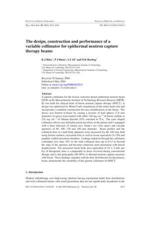
  • 9. The design, construction and performance of a variable collimator 2023 Figure 5. Total (neutron and photon) physical absorbed dose rate measured and calculated under simulated therapy conditions for a lateral irradiation in the 160 mm field. The leakage radiation represented by in-air absorbed dose rates (measured and calculated) is shown for comparison. The data do not include the dose deposited from capture events in boron and no dose weighting factors are applied. 3.2. Completed collimator The overall physical form of the collimator was chosen based on the desire to minimize leakage radiation to portions of the body outside the target volume but with exterior dimensions that allow the desired fields to be conveniently arranged with the fixed beam geometry. Shielding considerations necessitated an outer diameter at the base of the collimator that is large enough to shadow the outer diameter of the lead collimator further upstream in the beam line. The taper angle of the outer cone was then chosen to provide ample clearance around the collimator for positioning the patient while retaining sufficiently thick shielding in the walls of the collimator, for the smallest field sizes. The collimator was constructed using 7.6 mm diameter lead spheres that yielded a 40% volume fraction of epoxy, based on density measurements from the test pieces. A stepped cylindrical access port that penetrates the wall of the cone near its base was formed by casting an acrylic tube inside the mould. 3.3. Calculated and measured performance The total physical absorbed dose rates from neutrons and photons measured in the ART phantom and calculated in water for a lateral irradiation are shown in figure 5 as a function of displacement from the centre of the 160 mm field. Calculations and measurements of the in-air absorbed dose rate obtained with no phantom present are representative of leakage radiation from the beam line and are included in figure 5 for comparison. At any point outside the main beam, neutrons account for no more than 10% of the total absorbed dose from either leakage or scattered radiation. To compare the relative magnitude of radiation leaking from the beam line with that from the primary field, which is scattered within the patient, biological weighting factors were not applied nor was the dose from capture events in boron included. The overall estimated uncertainty for the measurements was 7% and the statistical uncertainties for the calculations range from 2% in the field to a maximum of 10% for the points furthest from the beam centreline. These are omitted from figure 5 for clarity.
  • 10. 2024 K J Riley et al Figure 6. In-air measurements of photon and epithermal neutron intensities along the central axis of the beam normalized to unity at the patient position for the 160 mm diameter aperture. Good agreement between the measured and calculated quantities is observed in-phantom even though the size of the detector is small (0.1 ml) compared to the large tally volumes (0.5–5 l) that were required. Relative to values measured in-air on the central axis of the beam, dose rates outside the collimator opening are reduced to approximately one-third and 10% at displacements of 3 and 15 cm from the edge of the aperture, respectively. The calculated in-air dose profile shows a much steeper gradient, falling to 10% at 35 mm outside the main beam which is significantly lower than the corresponding measurements. This discrepancy is believed to be due in part to the presence of albedo neutrons from the walls, ceiling and floor of the medical room that are missing from the computational model. The relative intensities of the epithermal neutrons and photons along the central axis of the beam from the base of the collimator to 0.2 m beyond the exit plane of the 160 mm diameter aperture are shown in figure 6. Each profile is normalized to unity at the end of the collimator at the patient position. The intensities of both the photons and epithermal neutrons decrease rapidly along the collimator axis at a rate of approximately 0.7% mm−1 near the patient position. Statistical uncertainties of 1 and 2% associated with the measurements and calculations are smaller than the symbols in the figure. The measurements represent an average over the 20 mm active length of the detector that was oriented along the beam axis and
  • 11. The design, construction and performance of a variable collimator 2025 Table 2. The dose equivalent per RBE weighted tumour Gy measured along the midline of the half- body phantom at different displacements from the central axis for the 160 mm diameter aperture. Dose equivalent was determined with weighting factors of 1, 10 and 20 for photons, neutrons and the high LET boron reaction products, respectively. A boron concentration of 15 µg g−1 was assumed for normal tissue. Therapeutic dose is determined using RBEs of 1.0 for photons and 3.2 for neutrons. A boron concentration of 52.5 µg g−1 is assumed for tumour with an associated RBE of 3.8. Displacement Dose equivalent per from central Anatomical RBE weighted tumour axis (m) region dose (mSv Gy−1) 0.21 Upper lungs 66 ± 5 0.32 Centre of lungs 19 ± 1.3 0.45 Upper intestines 6.4 ± 0.4 1.15 Feet 2.4 ± 0.2 positioned with an absolute uncertainty of 5 mm. The relative location of each measurement is, however, accurate to within 1 mm. Reasonable agreement is observed between the predictions and the measured profiles with the exception of the photon dose rates outside the field aperture where the measurements show a steeper attenuation. The measured dose equivalent at four different locations along the midline of the half- body phantom is summarized in table 2 and is expressed per RBE weighted Gy of tumour dose delivered at the midline of the phantom during a simulated patient irradiation. The tabulated results for the 160 mm field correlate the measurement positions with the anatomical features in these locations. The estimated uncertainty of 7% for these measurements is due principally to counting statistics of the gold foil activities used to determine the absorbed dose from neutron capture in nitrogen and boron (Riley et al 2003). A whole body dose equivalent of 24 ± 2 mSv per Gy of RBE weighted tumour dose was determined from a volume-weighted sum of the dose equivalents calculated in the neck and torso segments of the phantom. 3.4. Patient positioning The required beam entry point for any treatment field can be conveniently aligned with the central axis of the beam using a vertically mounted laser that is directed along the central axis of the collimator. The mirrors for reflecting the laser are contained in a tube that fits into the cylindrical access port in the collimator wall and includes optics that provide a beam’s eye view for aligning the patient in the fixed beam which would otherwise be difficult with little or no air gap. The laser and viewing system assembly are removed for an irradiation and replaced with a plug that was constructed separately in a manner similar to the collimator. When the plug is removed (and the laser installed), an interlock in the beam control system prevents an irradiation from commencing. Fiducial marks on the back wall of the medical room and on an insert for each aperture verify proper alignment of the laser with the geometric centre of the beam line when it is replaced. A photograph of the completed collimator and the laser/viewing optics are shown in figure 7. The length of the collimator for the 160 mm field extends 0.32 m from the wall of the medical room and is 0.31 m wide at its end, gradually increasing to 0.66 m at the wall. This geometry is well suited to brain irradiations since most patients are positioned supine on the treatment couch perpendicular to the beam, which does not interfere with the collimator. Smaller field sizes provide an even more favourable geometry as the collimator is lengthened with a thinner wall at the field aperture. The centreline of the beam in the medical room is 0.42 m above the floor and is at a comfortable height for medical staff to conduct patient
  • 12. 2026 K J Riley et al Figure 7. Left: photograph of the collimator mounted inside the FCB medical room with the 120 mm diameter aperture. Right: the laser and optical system are removed from the collimator following patient positioning prior to commencing irradiation. A cross laser is projected along the central axis of the beam when the laser and optics are installed for patient set-up that also allow a beam’s eye view along the central axis. set-up. The height of the beam also allows the possibility of seating the patient in a low chair, with the head reclined into the beam. Positioning for other potential tumour sites such as the torso, limbs and pelvis is also straightforward with this patient collimator. 4. Discussion and summary The design of the patient collimator for the FCB achieves a practical minimum in the increase of the FWHM for both the photon and neutron absorbed dose profiles relative to the geometric aperture size. Replacing a portion of the boron in the collimator with lithium proved effective in reducing the photon contamination produced by neutron capture in the collimator. Smaller apertures formed by adding sections to the end of the collimator have superior spatial profiles but reduced beam intensity by up to 40% compared with those provided by leaving the length of the collimator fixed and changing the taper of the inner surface. Even using the 80 mm diameter aperture with the lowest available intensity, irradiation times comparable to conventional radiotherapy can be achieved with the FCB (<20 min) for a peak dose in brain tissue of 12.5 (RBE) Gy, using BPA infused at 350 mg kg−1. An advantage of the additional space afforded by extending the collimator to form smaller apertures is to provide greater flexibility for patient positioning. The patient collimator was constructed from lead and epoxy with either boron carbide or lithium fluoride (95% enriched in 6Li), which (with the exception of enriched lithium) are inexpensive and readily available materials. The present configuration has a removable end segment that can be easily redesigned and constructed to provide an aperture of any size or shape. In addition, the present collimator can be moved forward several centimetres to allow, for example, the inclusion of a lithium (enriched in 6Li) filter that is now planned. The detectors that serve as beam monitors are positioned upstream of these variable components to maintain continuity in the measured output for all therapy field configurations. The shape of the final collimator and the axial laser that indicates the central axis of the beam and which can be viewed even when the beam aperture is covered makes patient
  • 13. The design, construction and performance of a variable collimator 2027 positioning easier for any irradiation site. Beam intensity at the patient position steadily reduces with increasing distance from the end of the collimator. The distance from the end of the collimator to the beam entry point on the surface of the patient is reproducible to within 1 mm and contributes an uncertainty of less than 1% in the fluence delivered to the patient. The MCNP model of the fission converter beam line proved a valuable tool for performing the parametric studies necessary to design the patient collimator. Satisfactory agreement is obtained between the absorbed dose rates measured outside the beam aperture and those calculated using MCNP. Similar agreement is observed for the relative epithermal neutron and photon intensities along the central axis of the beam. Leakage radiation through the walls of the collimator or from the beam line itself is only a small fraction of the dose received in regions outside the target volume. Within 0.15 m beyond the geometric edge of the aperture, the absorbed dose from leakage radiation contributes less than 10% of the total collateral dose to the patient. At displacements greater than 0.3 m from the central axis of the beam where the total dose equivalent is relatively low, leakage radiation becomes comparable to that from scatter within the patient. Further reduction of the beam leakage component will not significantly decrease the collateral dose received during therapy that mostly comes from scattering of the beam within the primary target volume. The highest dose equivalent measured was 66 mSv per therapy (RBE weighted) Gy at a position of 0.21 m from the central axis which is considerably greater than the 10 mSv Gy−1 reported near the edge of a 10 × 10 cm2 field for photon therapy (ICRP 1985). However, the average measured whole body dose of 24 mSv per (RBE) Gy to tumour is similar to the 20 mSv Gy−1 for the largest fields in photon therapy (Nath et al 1984) and less than the 37–70 mSv Gy−1 (Followill et al 1997) for advanced tomotherapy. In BPA-mediated BNCT, boron interactions produce between 60% and 80% of the total dose equivalent at all locations observed outside the field and occur principally with neutrons that are scattered from the primary beam. The relatively high dose equivalent attributed to the capture products released from boron makes these results very sensitive to the dose weighting factors and uptake parameters assumed. The simple construction technique and inexpensive materials employed have proved successful in building collimators that provide both desirable beam characteristics and effective patient shielding for epithermal neutron beams. The patient collimator as described in its initial configuration has already been used successfully for clinical brain irradiations at the MIT fission converter beam. Versatility in the design and ease of construction readily facilitate adaptation of this collimator to satisfy the needs of further clinical studies that are envisioned for BNCT. Acknowledgments The authors acknowledge the input of Dr Paul Busse, Jody Kaplan RN BSN, Dr Stead Kiger and Dr Robert Zamenhof in the design of the collimator. This work was supported by the US Department of Energy under contract number DEFG02-96ER62193. References Ali J 2001 The design optimization and construction of a patient collimator for the fission converter beam SM Thesis (Cambridge, MA: Massachusetts Institute of Technology) Busse P M et al 2003 A critical examination of the results from the Harvard–MIT NCT program phase I clinical trial of neutron capture therapy for intracranial disease J. Neurooncol. 62 111–21
  • 14. 2028 K J Riley et al Chanana A D et al 1999 Boron neutron capture therapy for glioblastoma multiforme: interim results from the phase I/II dose-escalation studies Neurosurgery 44 1182–93 Coderre J A, Capala J, Makar M and Diaz A Z 1997 Application of BNCT to other types of tumors Advances in Neutron Capture Therapy vol II, ed J C B Larsson and R Weinreich (Elsevier: Amsterdam) pp 649–53 Coderre J A, Makar M S, Micca P L, Nawrocky M M, Liu H B, Joel D D, Slatkin D N and Amols H I 1993 Derivations of relative biological effectiveness for the high-LET radiations produced during boron neutron capture irradiations of the 9L rat gliosarcoma in-vitro and in-vivo Int. J. Radiat. Oncol. Biol. Phys. 27 1121–9 Followill D, Geis P and Boyer A 1997 Estimates of whole body dose equivalent produced by beam intensity modulated conformal therapy Int. J. Radiat. Oncol. Biol. Phys. 38 667–72 ICRP 1985 Protection of the Patient in Radiation Therapy ICRP Publication 44 (Oxford: Pergamon) ICRP 1990 Recommendations of the International Commission on Radiological Protection ICRP Publication 60 (Oxford: Pergamon) ICRU 1989 Tissue Substitutes in Radiation Dosimetry and Measurement ICRU Report 44 (Bethesda, MA: ICRU) ICRU 1999 Prescribing, Recording and Reporting Photon Beam Therapy (Supplement to ICRU Report 50) ICRU Report 62 (Bethesda, MD: ICRU) ICRU 2000 Nuclear Data for Neutron and Proton Radiotherapy and for Radiation Protection ICRU Report 63 (Bethesda, MD: ICRU) Kiger W S III, Sakamoto S and Harling O K 1999 Neutronic design of a fission converter-based epithermal neutron beam for neutron capture therapy Nucl. Sci. Eng. 131 1–22 Harling O K and Riley K J 2002 A critical assessment of BNCT beams from fission reactors Research and Development in Neutron Capture Therapy ed W Sauerwein, R Moss and A Wittig (Monduzzi: Bologna) pp 159–62 Harling O K et al 2002 The fission converter-based epithermal neutron irradiation facility at the Massachusetts Institute of Technology Reactor Nucl. Sci. Eng. 140 223–40 Nath R, Epp E R, Laughlin J S, Swanson W P and Bond V P 1984 Neutrons from high-energy x-ray medical accelerators: an estimate of risk to the radiotherapy patient Med. Phys. 11 231–41 Pignol J P, Oudard H, Chauvel P, Sauerwein W, Gabel D and Prevot G 1998 Selective delivery of 10B to soft tissue sarcoma using 10B-L-borophenylalanine for boron neutron capture therapy Br. J. Radiol. 71 320–3 Riley K J 2001 Construction and characterization of a fission converter based epithermal neutron beam for BNCT PhD Thesis (Cambridge, MA: Massachusetts Institute of Technology) Riley K J, Binns P J and Harling O K 2003 Performance characteristics of the MIT fission converter based epithermal neutron beam Phys. Med. Biol. 48 943–58 Rogus R D, Harling O K and Yanch J C 1994 Mixed field dosimetry of neutron beams for boron neutron capture therapy at the MITR-II research reactor Med. Phys. 21 1611–25 Wilson B A 2001 Automatic control and monitoring of the MIT fission converter beam SM Thesis (Cambridge, MA: Massachusetts Institute of Technology)