
Recommandé
Contenu connexe
Tendances
Tendances (17)
Similaire à Vq5000
Similaire à Vq5000 (20)
Plus de kongurpkp
Dernier
Dernier (20)
Vq5000
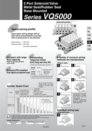
- 1. Cylinder Speed Chart Enclosure IP65 compliant Dust tight/Low jetproof type 5 Port Solenoid Valve Metal Seal/Rubber Seal Base Mounted Series VQ5000 A variety of common wiring methods are standardized. Space-saving profile Space-saving —— 40% less Capacity-saving — 50% less (In-house comparison) Compact with large flow capacity (Ideal for driving cylinders up to ø180) Outstanding response times and long service life (Metal seal with light/surge suppressor) VQ5100 32 mS (Single) VQ5200 17 mS (Double) 100 million cycles Accuracy ±3 mS ∗ According to SMC life test conditions kit (D-sub connector) kit (Lead wire)F L T1 S T IP65 compatible Enclosure Individual wiring type <Plug lead type> kit (Connector) C Grommet type IP65 compatible Enclosure ∗ For applications which demand high speed, high frequency, long life and a precise response time. kit (With individual terminal blocks) IP65 compatible IP65 compatible Enclosure Enclosure kit (Terminal block box) kit (Serial transmission) Series Average speed (mm/s) 1100 1000 900 800 700 600 500 400 300 200 100 0 VQ5100-„-04 VQ5101-„-04 Bore size Series MB, CA1 Pressure 0.5 MPa Load factor 50% Stroke 500 mm Series CS1 Pressure 0.5 MPa Load factor 50% Cylinder stroke 1000 mm ø50 ø63 ø80 ø100 ø125 ø140 ø160 ø180 ø200 ø250 System Components Speed controller AS420-04 Silencer AN400-04 SGP (Steel pipe) dia. x Length 10A x 1 m Perpendicular, upward actuation Horizontal actuation Clean space saving design with all pilot valves concentrated to one side with no protrusions in any direction ∗ It is when the cylinder is extending that is meter-out controlled by speed controller which is directly connected with cylinder, and its needle valve with being fully open. ∗ The average velocity of the cylinder is what the stroke is divided by the total stroke time. ∗ Load factor: ((Load weight x 9.8)/Theoretical force) x 100% Ⴇ 5 wiring types have been standardized to facilitate easy wiring work and maintenance. In addition, 3 of the wiring types are available with IP65 enclosures. <Plug-in type> Use as a guide for selection. Please confirm the actual conditions with SMC Sizing Program. 2-6-1 VQC SQ VQ0 VQ4 VQ5 VQZ VQD 1
- 2. Warning Push type (Tool required) Locking type (Option) Caution Caution Proper tightening torque (N·m) 1 to 1.8 A side A side A side COM COM COM B side B side VQ5100 1 VQ5200 1 VQ54 500 1 3 6 Note 1) There is no polarity. It can also be used as –COM. Note 2) The sub-plate is double wired even for the VQ510 .0 1 Plug lead: Grommet type Make connections to each corresponding wire. A COM B T Terminal block marking Model Single solenoid Double solenoid Bore ø6.1 Bore ø6.1 SOL.A COM SOL.B SOL.A COM SOL.B (–) Black (+) Red (–) White Lead wire color (–) Black (+) Red (–) White Lead wire color Black: A side solenoid (–) Red: COM (+) White: B side solenoid (–) (Not used for single solenoid) Green: (Not used for single or double.) PUSH TURN LOCK Black: A side solenoid (–) Red: COM (+) Red: COM (+) White: B side solenoid (–) Black: A side solenoid (–) Single solenoid Double solenoid StandardEnclosureIP65compliant Note) There is no polarity. It can also be used as –COM. COM Mounting screw (M4) (1) (2) Ȝ Applicable terminal 1.25-3s, 1.25Y-3, 1.25Y-3N, 1.25Y-3.5. Precautions Be sure to read before handling. For Safety Instructions and Solenoid Valve Precautions, refer to page 2-9-2. Since connected equipment will be actuated when the manual override is operated, first confirm that conditions are safe. Non-locking push type (Tool required) is standard. As an option, slotted locking type (Tool required) is available. Push down the manual override button with a small screwdriver, etc. Release the screwdriver and the manual override will return. Push down completely on the manual override button with a small screwdriver. While down, turn clockwise 90° to lock it. Turn it counterclockwise to release it. After confirming the gasket is correctly placed under the valve, securely tighten the bolts with the proper torque shown in the table below. Manual Override Operation Mounting of Valves Lead Wire Connection Plug-in sub-plate (With terminal block) Ȝ If the junction cover (1) of the sub-plate is removed, you can see the plug-in type terminal block (2) mounted inside the sub- plate. Ȝ The terminal block is marked as follows. Connect wiring to each of the power supply terminals. 2-6-2 Series VQ5000 Base Mounted 2
- 3. Caution Attaching and detaching connectors For obtaining the flow rate, refer to pages 2-1-8 to 2-1-11. Caution Caution DC: Single For Plug Lead Type AC: Single AC: Double Light assembly O-ring A side Mounting screw B side Guide Mounting indicator Note) It can be used with all voltages. DC: Double SOL ZNR – ( + ) + (–) SOL ZNR ZNR SOL A side – (+) B side – (+) COM + (–) SOL Light circuit assembly (Orange) A side light circuit assembly (Orange) B side light circuit assembly (Green) Light circuit assembly (Orange) A side light circuit assembly (Orange) B side light circuit assembly (Green) A side B side COM SOL SOL Light Circuit Board Part No. SOL.A SOL.B VQZ100-47-A VQZ100-47-B Proper tightening torque (N·m) 0.1 to 0.13 A B Light cover Lever connector Installation/Removal of light cover Ȝ Removal To remove the pilot cover pull it straight off. If it is pulled off at an angle, the pilot valve may be damaged or the protective O-ring may be scratched. Ȝ Installation Place the cover straight over the pilot assembly so that the pilot valve is not touched, and push it until the cover hook locks without twisting the protective O-ring. (When pushed in, the hook opens and locks automatically.) Ȝ Removal 1. Remove the mounting screw that holds the pilot valve using a small screwdriver. 2. When equipped with light, remove the light circuit board which is installed on the pilot valve by pulling it straight off the connector pins. Ȝ Installation 1. Insert the light circuit board straight onto the connector pins following the guide. If it is pushed in forcibly without following the guide, there is a danger of possibly bending the board contacts. 2. After confirming the gasket is correctly placed under the valve, securely tighten the bolts with the proper torque shown in the table below. Note) The mounting of pilot valves is not directional with respect to the A and B sides. However, the light circuit boards’ A side is orange and the B side is green. It must be mounted on the pilot valve in accordance with the mounting indicators. The light will not go on if the mounting is reversed. ȜTo attach a connector, hold the lever and connector unit between your fingers and insert straight onto the pins of the solenoid valve so that the lever’s pawl is pushed into the groove and locks. ȜTo detach a connector, remove the pawl from the groove by pushing the lever downward with your thumb, and pull the connector straight out. Note) Do not pull on the lead wires with excessive force. This can cause faulty and/or broken contacts. Installation and Removal of Light Cover Replacement of Pilot Valve Internal Wiring Specifications How to Calculate the Flow Rate 2-6-3 Series VQ5000 Base Mounted VQC SQ VQ0 VQ4 VQ5 VQZ VQD 3
- 4. Model Base mounted Series Number of solenoids VQ5000 Model Port size Metal seal Rubber seal Metal seal Rubber seal Metal seal Rubber seal Metal seal Rubber seal Metal seal Rubber seal Metal seal Rubber seal Rc 1/2 Single VQ51 0 VQ51 1 VQ52 0 VQ52 1 VQ53 0 VQ53 1 VQ54 0 VQ54 1 VQ55 0 VQ55 1 VQ56 0 VQ56 1 Double Double check Closed center Exhaust center Pressure center 2position3position 0 5 0 5 0 5 0 5 0 5 0 5 0 5 0 5 0 5 0 5 0 5 0 5 Flow Characteristics b Cvb 1 Ǟ 4/2 (P Ǟ A/B) 4/2 Ǟ 5/3 (A/B Ǟ EA/EB) Cv Standard Specifications Valve construction Fluid Maximum operating pressure Proof pressure Ambient and fluid temperatnre Lubrication Manual override Shock/Vibration resistance Protection structure Coil rated voltage Allowable voltage fluctuation Coil insulation type Min. operating pressure Power consumption (Current) ValvespecificationsSolenoidspecifications Single Double 3 position 24 VDC 12 VDC 100 VAC 110 VAC 200 VAC 220 VAC Metal seal Rubber seal 0.10 MPa 0.10 MPa 0.15 MPa 0.20 MPa 0.15 MPa 0.20 MPa 1.0 MPa Air/Inert gas 1.5 MPa –5 to 50°C (3) (1) Not required Push type/Locking type (Tool required) Option 150/30 m/s2 Dust tight (IP65 compatible) 12, 24 VDC, 100, 110, 200, 220 VAC (50/60 Hz) ±10% of rated voltage Class B or equivalent 1 W DC (42 mA), 0.5 W DC (21 mA) (3) 1 W DC (83 mA), 0.5 W DC (42 mA) Note (3) Inrush 1.2 VA (12 mA), Holding 1.2 VA (12 mA) Inrush 1.3 VA (11.7 mA), Holding 1.3 VA (11.7 mA) Inrush 2.4 VA (12 mA), Holding 2.4 VA (12 mA) Inrush 2.6 VA (11.7 mA), Holding 2.6 VA (11.7 mA) (2) Plug-in unit JIS Symbol 2 position single 2 position double (Metal) 2 position double (Rubber) 3 position closed center 3 position exhaust center 3 position pressure center 3 position double check (A) 4 (B) 2 1 (P) 5 (R1) 3 (R2) (A) 4 (B) 2 1 (P) 5 (R1) 3 (R2) (A) 4 (B) 2 1 (P) 5 (R1) 3 (R2) (A) 4 (B) 2 1 (P) 5 (R1) 3 (R2) (A) 4 (B) 2 1 (P) 5 (R1) 3 (R2) (A) 4 (B) 2 1 (P) 5 (R1) 3 (R2) (A) 4 (B) 2 1 (P) 5 (R1) 3 (R2) Plug lead unit Note 1) Use dry air to prevent condensation when operating at low temperatures. Note 2) Impact resistance: No malfunction occurred when it is tested with a drop tester in the axial direction and at the right angles to the main valve and armature in both energized and de-energized states every once for each condition. (Values at the initial period) Vibration resistance: No malfunction occurred in a one-sweep test between 45 and 2000 Hz. Test was performed at both energized and de-energized states in the axial direction and at the right angles to the main valve and armature. (Values at the initial period) Note 3) Values inside ( ) denote the low wattage (0.5 W) specifications. Note) Value for valve on sub-plate. C[dm3/(s.bar)] C[dm3/(s.bar)] 12 16 12 16 11 12 12 14 12 13 8.0 8.3 0.14 0.33 0.14 0.33 0.24 0.33 0.13 0.39 0.23 0.32 — — 2.9 4.4 2.9 4.4 2.6 3.4 2.9 3.9 2.9 3.4 — — 14 17 14 17 11 13 14 16 13 14 8.5 9.0 0.18 0.31 0.18 0.31 0.23 0.37 0.18 0.35 0.24 0.40 — — 3.4 4.7 3.4 4.7 2.8 3.7 3.4 4.5 3.3 3.9 — — Series VQ5000 Base Mounted Plug-in/Plug Lead: Single Unit Response time (ms) Standard 1 W AC Low wattage 0.5 W Weight (kg) 0.59 (0.67) 0.58 (0.66) 0.62 (0.70) 0.60 (0.68) 0.65 (0.73) 0.58 (0.66) 0.65 (0.73) 0.58 (0.66) 0.65 (0.73) 0.58 (0.66) 1.17 (1.25) 1.10 (1.18) 35 or less 40 or less 20 or less 25 or less 50 or less 60 or less 50 or less 60 or less 50 or less 60 or less 62 or less 75 or less 38 or less 43 or less 23 or less 28 or less 53 or less 63 or less 53 or less 63 or less 53 or less 63 or less 65 or less 78 or less 38 or less 43 or less 23 or less 28 or less 53 or less 63 or less 53 or less 63 or less 53 or less 63 or less 65 or less 78 or less 2-6-4 4
- 5. How to Order Valves Seal 1 0 1 Metal seal Rubber seal VQ5 Body 5 04P Electrical entry 2 Type of actuation Light/Surge voltage suppressor Manual override Enclosure 0VQ5 0 5 G 51Plug-in Plug lead Body 0: Plug-in sub-plate Porting specifications Nil B Side ported Bottom ported Port size Nil Without sub-plate (For manifold) Nil Dust-protected Dusttight/Low jetproof type (IP65) W Nil: Non-locking push type (Tool required) B: Slotted locking type (Tool required) Nil E Yes Without light, With surge voltage suppressor 04 Rc 1/2 G Lead wire length 0.6 m H Grommet Coil voltage 31 4 2 5 6 MetalRubber 5: Plug lead sub-plate 1 2 3 4 5 6 100 VAC (50/60 Hz) 200 VAC (50/60 Hz) 110 VAC (50/60 Hz) 220 VAC (50/60 Hz) 24 VDC 12 VDC Lead wire length 1.5 m Function Nil Y R Standard type (1 W) Low wattage type (0.5 W) External pilot (1) Note) (2) How to Order Sub-plates VQ5000 Port size 04 Rc 1/2Porting specifications Nil B Side ported Bottom portedEnclosure Nil W Dust-protected Dusttight/Low jetproof type Electrical entry P S Plug-in conduit terminal Plug lead 2 position single 3 position closed center 2 position double 3 position exhaust center 2 position double 3 position pressure center 3 position double check (A) 4 (B) 2 1 (P) 5 (R1) 3 (R2) 1 (P) 5 (R1) 3 (R2) (A) 4 (B) 2 (A) 4 (B) 2 1 (P) 5 (R1) 3 (R2) (A) 4 (B) 2 1 (P) 5 (R1) 3 (R2) (A) 4 (B) 2 1 (P) 5 (R1) 3 (R2) (A) 4 (B) 2 1 (P) 5 (R1) 3 (R2) Bore ø6.1 Bore ø6.1 PU SH TU RN LOC K Note1) For bottom ported, port size is Rc 1/2. Note2) For thread standard, refer to page 2-6-39. Note) Not required for plug lead type. (A) 4 (B) 2 1 (P) 5 (R1) 3 (R2) Note) For details about the double check type, refer to page 2-6-36. Note) For thread standard, refer to page 2-6-39. Note 1) Applicable to DC specifications. Note 2) For details about external pilot specifications, refer to page 2-6- 39. Note 3) When two or more symbols are specified, indicate them alphabetically. Replacement of pilot valve assembly (Voltage) • Refer to pages 2-6-40 to 2-6-41 for pilot valve assembly part numbers. • Refer to page 2-6-3 for replacement method. 2-6-5 Series VQ5000Plug-in/Plug Lead: Single Unit Base Mounted VQC SQ VQ0 VQ4 VQ5 VQZ VQD 5
- 6. Plug-in Type 2 position single: VQ5100 1 3 position double check: VQ5600 12 position double: VQ5200 1 3 position closed center: VQ5300 1 3 position exhaust center: VQ5400 1 3 position pressure center:VQ5500 1 Conduit terminal 195 122 106 59.5 73 4(A) port 17.5 13.5 2(B) port Indicator light Manual override 35 53 2-ø6.5 Mounting hole 2-Rc 3/8 5(R1), 3(R2) port 3-Rc 1/2 1(P), 4(A), 2(B) port Rc 1/8 External pilot port G1/2 Electrical entry 5-Rc 1/2 1(P), 4(A), 2(B), 5(R1), 3(R2) port 40 1613 16 53 66 26.5 16 4(A),2(B)port 18 18.4 31.5 37 41 50 98 M5groundscrew 66 53 VQ5000 2 195 73 59.5 27.527.5 17.5 13.5 35 53 27.5 195(200.5) 4 (A) port 13.52 (B) port 41 41 27.5Rc 1/8 PE port 14 5 4 2 SMC 1 3 12 B A A 5 4 2 1 3 SMC PE X P R1 R2 Indicator light 73(78.5)122 106 59.5 214 121.8 35 53 2-ø6.5 Mounting hole Indicator light Manual override 91.5 59.5105.8 (A port)17.5 13.5 (B port) 22 SMC24 A AB B 14 R1 R2 P PE X 5 1 3 12 Manual override 35 53 2-ø6.5 Mounting hole G1/2 Electrical entry Rc 1/8 PE port Rc 1/8 External pilot port 5-Rc 1/2 (P), 4(A), 2(B), 5(R1), 3(R2) port 40 18.4 18 31.5 37 41 50 98 66 53 40 53 66 162 50 41 37 31.5 18 18.5 27.5 27.5 41 41 41 27.527.5Rc 1/8 PE port Rc 1/8 external pilot port 5-Rc 1/2 G1/2 Electricalentry 41 Bottom ported drawing PE P X R2R1 1 3514 12 24 SMC A B AB 1(P), 4(A), 2(B), 5(R1), 3(R2) port Numbers inside ( ) are for metal seal 3 position type 2-6-6 Series VQ5000 Base Mounted 6
- 7. Plug Lead Type 2 position single: VQ5150 1-„G H Numbers inside ( ) are for metal seal 3 position type 3 position double check: VQ5650 1-„G H2 position double: VQ5250 1-„G H 3 position closed center: VQ5350 1-„G H 3 position exhaust center: VQ5450 1-„G H 3 position pressure center: VQ5550 1-„G H Grommet Bottom ported drawing 194.5 4(A) port 17.5 13.5 2 (B) port 121.3 73.2 53 59.5 SMC24 A A B 14 5 1 3 12 Indicator light Manual override 2-ø6.5 Mounting hole 40 53 66 35 53 194.5 121.3 73.2 59.5 27.527.52-Rc 3/8 5(R1), 3(R2) port 3-Rc 1/2 (P), 4 (A), 2 (B) port Rc 1/8 External pilot port 5-Rc 1/2 1(P), 4(A), 2(B), 5(R1), 3(R2) port Rc 1/8 PE port VQ5000 17.5 13.5 35 53 1613 16 53 66 16M5groundscrew 4(A),2(B)port26.5 18 31.5 37 41 50 98 27.5 41 41 27.5 T 5 1 3 24 SMC 194.5(200) 121.3 53 73.2(78.7) 4(A) port 17.5 35 27.5 27.5 41 41 53 13.5 2(B) port 59.5 213 121.3 91.5 53 2-ø6.5 Mounting hole Manual override Indicator light Rc 1/8 PE port Rc 1/8 External pilot port 5-Rc 1/2 1(P), 4(A), 2(B), 5(R1), 3(R2) port 35 27.5 27.5 41 41 53 4 (A) port17.5 13.5 2(B) port 59.5 SMC24 A AB B 14 5 PE X P R1 R2 1 3 12 2-ø6.5 Mounting hole 40 66 53 66162 50 41 37 31.5 18 53 40 Manual override Indicator light Rc 1/8 PE port Rc 1/8 External pilot port 5-Rc 1/2 1(P), 4(A), 2(B), 5(R1), 3(R2) port 18 31.5 37 41 50 98 PE X P R1 R2 PE P X R2R1 1 3514 12 24 SMC A B AB 2-6-7 Series VQ5000Plug-in/Plug Lead: Single Unit Base Mounted VQC SQ VQ0 VQ4 VQ5 VQZ VQD 7
- 8. Κ. ∇ Series VQ5000 Base Mounted Plug-in Unit Nil CD1 CD2 CU1 CU2 K N SB SD SU W Option Option None Exhaust cleaner for Rc 1: D side exhaust Exhaust cleaner for Rc 1 1/2: D side exhaust Exhaust cleaner for Rc 1: U side exhaust Exhaust cleaner for Rc 1 1/2: U side exhaust Special wiring specifications (Except double wiring) Name plate (T kit only) Direct exhaust with silencer box: Exhaust from both D and U sides Direct exhaust with silencer box: D side exhaust Direct exhaust with silencer box: U side exhaust IP65 enclosure (except F and T1 kits) (2) (2) (2) (2) (4) (3) (2) (2) 08 How to Order Manifold Manifold 1 1 5 Plug-in Unit 01 Minimum number of stations depends on the kit. (Refer to the table below.) 1 station Station VV5Q Series 5 VQ5000 03 F U1 Cylinder port 03 04 B CM Rc 3/8 Rc 1/2 Bottom ported Rc 1/2 Mixed Kit type U D U D Kit/Electrical entry/Cable length F L T1 S kit (D-sub connector) kit (Lead wire cable) kit (Individual terminal block kit) T kit (Terminal block box kit) kit (Serial transmission unit) IP65 compatible IP65 compatible IP65 compatible Connector entry direction D side U side Electrical entry Unit mounting position D side D side U side U sideD0 D1 D2 D3 U0 U1 U2 U3 Kit F Kit F Without cable Cable length 1.5 m Cable length 3 m Cable length 5 m 1 to 12 stations 1 to 12 stations Box mounting position D side U side TD TU Terminal block box 2 to 12 stations Kit T1 With terminal blocks 1 to 12 stations D0 D1 D2 U0 U1 U2 Kit L Kit L Cable length 0.6 m Cable length 1.5 m Cable length 3 m SD SU O A B BB C D F1 J1 J2 K Q R1 R2 U V G H Without SI unit With general type SI unit (Series EX300) Mitsubishi Electric Corp.: MELSECNET/MINI-S3 Data Link System Mitsubishi Electric Corp.: MELSECNET/MINI-S3 Data Link System (2 power supply systems) OMRON Corp.: SYSBUS Wire System SHARP Corp.: Satellite I/O Link System NKE Corp.: Uni-wire System (16 output points) SUNX Corp.: S-LINK System (16 output points) SUNX Corp.: S-LINK System (8 output points) Fuji Electric Co.: T-LINK Mini System DeviceNet, CompoBus/D (OMRON Corp.) OMRON Corp.: CompoBus/S System (16 output points) OMRON Corp.: CompoBus/S System (8 output points) JEMANET (JPCN-1) Mitsubishi Electric Corp.: CC-LINK System Rockwell Automation: Allen Bradley Remote I/O (RIO) System NKE Corp.: Uni-wire H System 2to12stations Symbol The valve voltage is 24 VDC and it is equipped with light/surge voltage suppressor. Note) Note)In case of mixed specification, indicate on the manifold specification sheet. Note) The drawing shows a VV5Q51-0504FDO. ... ... Note 1) When two or more symbols are specified, indicate them alphabetically. Example) -CD1K Note 2) Combination of [C „] and [S ] is not possible. Note 3) Available only with F, L and T1 kits. Note 4) Specify the wiring specifications on the manifold specification sheet. (Except L kit) Κ. ∇ Indicator light Type of connection A, B port R1 port R2 Port P port External pilot supply port 2-6-8 8
- 9. Manifold Specifications VQ5000 Series Base model Type of connection í F kit–D-sub connector í T kit–Terminal block box í T1 kit–Individual terminal block kit í L kit–Lead wire í S kit–Serial transmission 4(A), 2(B) port location Porting specifications Port size 1(P) , 5(R1) , 3(R2) 4(A), 2(B) Side Bottom Rc 3/4 Option Direct exhaust with silencer box Rc 3/8 Rc 1/2 Rc 1/2 Maximum applicable stations F, L, T1 kits 12 stations T kit 11 stations S kit 9 stations Applicable solenoid valve 5 station weight (kg) 4.1 • L kit • Not including solenoid valve weight. Note) For details about international standard threads other than Rc threads, refer to “Option” on page 2-6-39. Manifold Option Note) VV5Q51-„„„ VQ5L00 VQ5L01 Flow Characteristics at the Number of Manifold Stations (Operated individually) Model Passage/Stations 2 position metal seal VQ5 00 2 position rubber seal VQ5 01 C [dm3/(s·bar)] b Cv C [dm3/(s·bar)] b Cv C [dm3/(s·bar)] b Cv C [dm3/(s·bar)] b Cv Station 5Station 1 Station 10 Note) For port size Rc 1/2 1 2 1 2 1 Ǟ 4/2 (P Ǟ A/B) 4/2 Ǟ 5/3 (A/B Ǟ EA/EB) 1 Ǟ 4/2 (P Ǟ A/B) 4/2 Ǟ 5/3 (A/B Ǟ EA/EB) 11 0.24 2.7 12 0.14 2.9 12 0.33 3.4 16 0.33 4.4 11 0.24 2.7 12 0.14 2.9 12 0.33 3.4 16 0.33 4.4 11 0.24 2.7 12 0.14 2.9 12 0.33 3.4 16 0.33 4.4 • Refer to pages 2-6-34 to 2-6-38 for detailed dimensions of each option. • For replacement parts, refer to page 2-6-43. 03 04 LO CK PU SH Blanking plate assembly VVQ5000-10A-1 Individual SUP spacer VVQ5000-P-1- Throttle valve spacer VVQ5000-20A-1 SUP stop valve spacer VVQ5000-37A-1 SUP block plate VVQ5000-16A-1 Direct exhaust with silencer box [-S ] For exhaust cleaner mounting [-C „] Release valve spacer VVQ5000-24A-1D D U D U Individual EXH spacer VVQ5000-R-1- EXH block plate VVQ5000-16A-2 Double check spacer with residual pressure release valve VVQ5000-25A-1 Interface regulator ARBQ5000-00- -1 03 04 A B P 2-6-9 Series VQ5000Plug-in Unit Base Mounted VQC SQ VQ0 VQ4 VQ5 VQZ VQD 9
- 10. When two or more symbols are specified, indicate them alphabetically. Example) -CD1K. Combination of [C „] and [S ] is not possible. Specify the wiring specifications on the manifold specification sheet. Kit (D-sub Connector kit)F Manifold Specifications Series VQ5000 Porting specifications 4(A), 2(B) port location Port size 1(P), 5(R1), 3(R2) 4(A), 2(B) Side Bottom Applicable stations Rc 3/4 Rc 3/8 Rc 1/2 Rc 1/2 Max. 12 stations D-Sub Connector Kit (25Pins) VV5Q Manifold Option 08 02 2 stations Stations How to Order Manifold 12 12 stations Nil CD1 CD2 CU1 CU2 K (3) SB SD SU Option None Exhaust cleaner for Rc 1: D side exhaust Exhaust cleaner for Rc 1 1/2: D side exhaust Exhaust cleaner for Rc 1: U side exhaust Exhaust cleaner for Rc 1 1/2: U side exhaust Special wiring specifications (Except double wiring) Direct exhaust with silencer box: For mounting on both D and U sides Direct exhaust with silencer box: D side exhaust Direct exhaust with silencer box: U side exhaust F03 U Cylinder port Rc 3/8 Rc 1/2 Bottom ported Rc 1/2 Mixed 03 04 B CM 1 Plug-in unit AXT100-DS25- 015 030 050 D-sub connector cable assemblies can be ordered with manifolds. Refer to How to Order Manifold. D-sub Connector Cable Assembly Terminal No. Cable assembly Ȝ 1 2 3 4 5 6 7 8 9 10 11 12 13 14 15 16 17 18 19 20 21 22 23 24 25 Lead wire color Black Brown Red Orange Yellow Pink Blue Purple Gray White White Yellow Orange Yellow Pink Blue Purple Gray Orange Red Brown Pink Gray Black White Dot marking None None None None None None None White Black Black Red Red Red Black Black White None None Black White White Red Red White None D-sub Connector Cable Assembly (Option) Electric Characteristics Cable length (L) Assembly part no. Note 1.5 m 3 m 5 m AXT100-DS25-015 AXT100-DS25-030 AXT100-DS25-050 Cable 25 cores x 24AWG Item Characteristics Conductor resistance Ω/km, 20°C Voltage limit VAC, 1 min. Insulation resistance MΩkm, 20°C 65 or less 1000 5 or less Connector manufacturers’ example • Fujitsu, Ltd. • Japan Aviation Electronics Industry, Ltd. • J.S.T. Mfg. Co., Ltd. • Hirose Electric Co., Ltd. 11 Series 5 VQ5000 5 Connector entry direction D U D side entry U side entry Cable (Length) 0 1 2 3 Without cable Cable length 1.5 m Cable length 3 m Cable length 5 m U D U D Multi-core vinyl cable 0.3 mm2 x 25C 2-M2.6 x 0.45 Socket side Terminal no. ≅ ø10 47.04 55 16 44 8 L 1············13 14············25 Κ. ∇ Symbol SMC Ȝ Simplification and labor savings for wiring work can be achieved by using a D-sub connector for the electrical connection. Ȝ Using connector for flat ribbon cable (25P) conforming to MIL standard permits the use of connectors put on the market and gives a wide interchangeability. Ȝ Connector entry can be selected on either the U side or the D side according to the mounting orientation. Ȝ Maximum stations are 12. ∗ For other commercial connectors, use a 25 pins type with female connector conforming to MIL-C-24308. Note) The min. bending radius of D-sub cable is 20 mm. ... ... Terminal no. Note 1) Note 2) Note 3) 2-6-10 Series VQ5000 Base Mounted 10
- 11. VQ 5 How to Order Valves Type of actuation Series 1 2 3 4 5 6 2 position single 2 position double 3 position closed center 3 position exhaust center 3 position pressure center 3 position double check Seal 0 1 Metal seal Rubber seal Coil voltage Nil E Yes Without light, with surge voltage suppressor Nil B Non-locking push type (Tool required) Locking type (Tool required) Manual override Light/Surge voltage suppressor 5 VQ5000 <Example> D-sub connector kit with cable (3 m) VV5Q51-0503FD2 ··1 set ∗VQ5100-5 ··········· 2 sets ∗VQ5200-5 ··········· 2 sets ∗VQ5300-5 ··········· 1 set – Manifold base part no. – Valve part no. (Stations 1 and 2) – Valve part no. (Stations 3 and 4) – Valve part no. (Station 5) Prefix the asterisk to the part nos. of the solenoid valve, etc. SOL.A 1 (–) (+) Black None SOL.B 14 (–) (+) Yellow Black 1 station SOL.A 2 (–) (+) Brown None SOL.B 15 (–) (+) Pink Black 2 stations SOL.A 3 (–) (+) Red None SOL.B 16 (–) (+) Blue White 3 stations SOL.A 4 (–) (+) Orange None SOL.B 17 (–) (+) Purple None 4 stations SOL.A 5 (–) (+) Yellow None SOL.B 18 (–) (+) Gray None 5 stations SOL.A 6 (–) (+) Pink None SOL.B 19 (–) (+) Orange Black 6 stations SOL.A 7 (–) (+) Blue None SOL.B 20 (–) (+) Red White 7 stations SOL.A 8 (–) (+) Purple White SOL.B 21 (–) (+) Brown White 8 stations SOL.A 9 (–) (+) Gray Black SOL.B 22 (–) (+) Pink Red 9 stations SOL.A 10 (–) (+) White Black SOL.B 23 (–) (+) Gray Red 10 stations SOL.A 11 (–) (+) White Red SOL.B 24 (–) (+) Black White 11 stations SOL.A 12 (–) (+) Yellow Red SOL.B 25 (–) (+) White None 12 stations COM. 13 (+) (–) Orange Red Terminal no. Polarity Lead wire color Dot marking Positive common specifications Note)Negative common specifications Standard wiring Stations are counted starting from the first station on the D side. Ȝ Electrical wiring specifications Special Wiring Specifications 0 0 51 1 2 3 4 5 6 100 VAC (50/60 Hz) 200 VAC (50/60 Hz) 110 VAC (50/60 Hz) 220 VAC (50/60 Hz) 24 VDC 12 VDC Function Nil Y R Standard type (1 W) Low wattage type (0.5 W) External pilot (1) (2) How to Order Manifold Assembly D-sub connector assembly (AXT100-DS25- ) Wire colors D-sub connector 25 24 23 14 15 16 17 18 19 20 21 22 12 11 10 1 2 3 4 5 6 7 8 9 13 D-sub connector Connector terminal no. 25 24 23 14 15 16 17 18 19 20 21 22 12 11 10 1 2 3 4 5 6 7 8 9 13 COM D side U side 1 2 3 ············Stations 3 m D side U side 1 2 3 ······· Stations Double wiring (connected to SOL. A and SOL. B) is adopted for the internal wiring of each station, regardless of valve and option types. Mixed single and double wiring is available as an option. For details, refer to below. Κ. ∇ ∇ 015 030 050 Double wiring (connected to SOL. A and SOL. B) is used for the internal wiring of each station regardless of valve and option types. Mixed single and double wiring is available as an option. 1. How to Order Indicate option symbol “-K” in the manifold part number and be sure to specify station positions for single or double wiring on the manifold specification sheet. 2. Wiring specifications Connections begin with the A side solenoid of the first station being connected to terminal no. 1, and continue in the order indicated by the arrows in the drawing without skipping any terminals. However, the maximum number of stations is 12. Specify the part numbers for valves and options together beneath the manifold base part number. Enter in order starting from the first station on the D side. When entry of part numbers becomes complicated, indicate in the manifold specification sheet. Note) There is no polarity. It can also be used as a negative common. Note 1) Applicable to DC specifications. Note 2) Refer to page 2-6-39 for details on external pilot specifications. Note 3) When two or more symbols are specified, indicate them alphabetically. 2-6-11 Series VQ5000Plug-in Unit Base Mounted VQC SQ VQ0 VQ4 VQ5 VQZ VQD 11
- 12. Kit (D-sub Connector kit)F U side D side n ····················· 6 5 4 3 2 1 Stations Applicable connector: D sub connector (25P) (Conforming to MIL-C-24308) 83 29.5 29.5 36 2-Rc 1/8 (Pilot EXH port) 12 21 47.5 6-Rc 3/4 (P), 5(R1), 3(R2) port 9 9 59.246.8 179 19 When U side mounting (FU) Indicator light Manual override L1 L2 58.5P=41 106 With connector on D side (FD) 107.8 179 (Single, Double, 3 position, Rubber type) 184.5 (3 position, metal type) R4.5 83.5 34.5 55.5 M5 ground screw 2n-Rc 3/8, 1/2 4(A), 2(B) port 34.5 48 68.5P=41 15.5 17 22 51 69 117 2-Rc 1/8 (External pilot port) SMCSMCSMCSMCSMC 5R1 PE 3 1P SMC R2 AAAAA AB BBBBB ABABAAB 12X B2 A4 B2 A4 B2 A4 B2 A4 B2 A4 B2 A4 X12 2-6-12 Series VQ5000 Base Mounted 12
- 13. Bottom ported drawing ····················· 1 117 137 2 158 178 3 199 219 4 240 260 5 281 301 6 322 342 7 363 383 8 404 424 9 445 465 10 486 506 11 527 547 12 568 588 L1 L2 L n Formula: L1 = 41n + 76, L2 = 41n + 96 n: Stations (Maximum 12 stations)Dimensions U side D side 1 Stations 2 3 4 5 6 n 83.5 34.5 55.5 M5 ground screw 2-Rc 1/8 (External pilot port) 15.5 22 51 69 117 34.5 46 68.5P=41 42 16 107.8 179 With connector on D side (FD) P=41 L1 L2 58.5 2n-Rc 1/2 4(A), 2(B) port 9 9 106 46.859.2 With connector on U side (FU)SMCSMCSMCSMCSMC A B A B A B A B A B A B B2 A4 B2 A4 B2 A4 B2 A4 B2 A4 B2 X12 A4 X12 2-6-13 Series VQ5000Plug-in Unit Base Mounted VQC SQ VQ0 VQ4 VQ5 VQZ VQD 13
- 14. When two or more symbols are specified, indicate them alphabetically. Example) -CD1K. Combination of [CD U„] and [SD U] is not possible. Specify the wiring specifications on the manifold specification sheet. Kit (Terminal block box kit)T Manifold Specifications Series VQ5000 Porting specifications 4(A), 2(B) port location Port size 1(P) , 5(R1) , 3(R2) 4(A) , 2(B) Side Bottom Applicable stations Rc 3/4 Rc 3/8 Rc 1/2 Rc 1/2 Max. 12 stations Terminal Block Connections VV5Q Manifold Option 08 02 2 stations Stations How to Order Manifold 12 12 stations Nil CD1(2) CD2(2) CU1(2) CU2(2) K(4) N SD(2) SU(2) W Option None Exhaust cleaner for Rc 1: D side exhaust Exhaust cleaner for Rc 1 1/2: D side exhaust Exhaust cleaner for Rc 1: U side exhaust Exhaust cleaner for Rc 1 1/2: U side exhaust Special wiring specification (Except double wiring) Name plate Direct exhaust with silencer box: D side exhaust Direct exhaust with silencer box: U side exhaust IP65 enclosure T03 K Cylinder port Rc 3/8 Rc 1/2 Bottom ported Rc 1/2 Mixed 03 04 B CM 1 Plug-in unit 1 Series 5 VQ5000 Box mounting position D U D side mounting U side mounting 5 IP65 compliant Proper tightening torque (N·m) Ȝ Applicable terminal 1.25-3s, 1.25Y-3, 1.25Y-3N, 1.25Y-3.5 0.7 to 1.2 Symbol Mounting screw (M4) Terminal block cover Gasket Electrical entry 2-G3/4 M3 screw 6 mm Add 1 station for terminal block box. The maximum number of stations can be expanded with optional special wiring specifications. Refer to page 2-6-15 for details. Ȝ Enclosure IP65 compliant Ȝ This type has a small terminal block inside a junction box. The provision of a G 3/4 electrical entry allows connection of conduit fittings. Ȝ Maximum stations are 11. (12 stations as an option) Ȝ1 station is used for terminal block box mounting. Step 1. How to remove terminal block cover Loosen the 4 mounting screws (M4) and open the terminal block cover. Step 2. The diagram on the right shows the terminal block wiring. All stations are provided with double wiring regardless of the valves which are mounted. Connect each wire to the power supply side, according to the markings provided inside the terminal block. Step 3. How to attach the terminal block cover Securely tighten the screws with the torque shown in the table below, after confirming that the gasket is installed correctly. ··· ··· Note 1) Note 2) Note 1) Note 2) Note 3) 2-6-14 Series VQ5000 Base Mounted 14
- 15. VQ 5 How to Order Valves Type of actuation Series 1 2 3 4 5 6 2 position single 2 position double 3 position closed center 3 position exhaust center 3 position pressure center 3 position double check Seal 0 1 Metal seal Rubber seal Coil voltage Nil E Yes Without light, with surge voltage suppressor Nil B Non-locking push type (Tool required) Locking type (Tool required) Manual override Light/Surge voltage suppressor 5 VQ5000 <Example> Terminal block box kit VV5Q51-0603TU ···· 1 set ∗ VQ5100-5 ············· 2 sets ∗ VQ5200-5 ············· 2 sets ∗ VQ5300-5 ············· 1 set —Manifold base part no. —Valve part no. (Stations 1 and 2) —Valve part no. (Stations 3 and 4) —Valve part no. (Station 5) SOL.A 1A (–) (+) SOL.B 1B (–) (+) 1 station SOL.A 2A (–) (+) SOL.B 2B (–) (+) 2 stations SOL.A 3A (–) (+) SOL.B 3B (–) (+) 3 stations SOL.A 4A (–) (+) SOL.B 4B (–) (+) 4 stations SOL.A 5A (–) (+) SOL.B 5B (–) (+) 5 stations SOL.A 6A (–) (+) SOL.B 6B (–) (+) 6 stations SOL.A 7A (–) (+) SOL.B 7B (–) (+) 7 stations SOL.A 8A (–) (+) SOL.B 8B (–) (+) 8 stations SOL.A 9A (–) (+) SOL.B 9B (–) (+) 9 stations SOL.A 10A (–) (+) SOL.B 10B (–) (+) 10 stations (+) (–) Terminal no. Polarity Positive common Negative common Stations are counted starting from the first station on the D side. Ȝ Electrical wiring specifications (IP65 available) Special Wiring Specifications 0 0 51 1 2 3 4 5 6 100 VAC (50/60 Hz) 200 VAC (50/60 Hz) 110 VAC (50/60 Hz) 220 VAC (50/60 Hz) 24 VDC 12 VDC Function Nil Y R Standard type (1 W) Low wattage type (0.5 W) External pilot (1) (2) How to Order Manifold Assembly COM Nil Dusttight Enclosure W Dusttight/Low jetproof type (IP65) D side U side 1 2 3 ············Stations Standard wiring Double wiring (connected to SOL. A and SOL. B) is adopted for the internal wiring of each station, regardless of valve and option types. Mixed single and double wiring is available as an option. 2-G3/4 Electrical entry 1ACOM2A3A4A5A6A7A8A9A10A 1B2B3B4B5B6B7B8B9B10B 1B 1A 2B 2A 3B 3A 4B 4A 5B 5A 6B 6A 7B 7A 8B 8A 9B 9A 10B 10ACOM 1ACOM2A3A4A5A6A7A8A9A10A 1B2B3B4B5B6B7B8B9B10B 1B 1A 2B 2A 3B 3A 4B 4A 5B 5A 6B 6A 7B 7A 8B 8A 9B 9A 10B 10ACOM Double wiring (connected to SOL. A and SOL. B) is used for the internal wiring of each station regardless of valve and option types. The optional specification permits mixture of single and double wiring. However, the maximum number of stations is 12. 1. How to Order Indicate option symbol (“–K”) in the manifold part number and be sure to specify station positions for single or double wiring on the manifold specification sheet. 2. Wiring specifications Connections begin with the A side solenoid of the first station being connected to terminal no. 1, and continue in the order indicated by the arrows in the drawing without skipping any terminals. Specify the part numbers for valves and options together beneath the manifold base part number. Prefix the asterisk to the part nos. of the solenoid valve, etc. Enter in order starting from the first station on the D side. When entry of part numbers becomes complicated, indicate in the manifold specification sheet. Note) There is no polarity. It can also be used as a negative common. Applicable to DC sepecifications. Refer to page 2-6-39 for details on external pilot specifications. When two or more symbols are specified, indicate them alphabetically. Note 1) Note 2) Note 3) 2-6-15 Series VQ5000Plug-in Unit Base Mounted VQC SQ VQ0 VQ4 VQ5 VQZ VQD 15
- 16. Kit (Terminal block box kit)T ····················· U side D side 1 Stations 2 3 4 5 6 n 83 29.5 29.5 36 2-Rc 1/8 (Pilot EXH port) 12 21 47.5 6-Rc 3/4 (P), 5(R1), 3(R2) port 179 46.8 59.2 106 9 9 19 Indicator light Manual override L2 L1 58.5P=41 107.8 179 (Single, Double, 3 position, Rubber type) 184.5 (3 position, Metal type) R4.5 144.5 143 112.5 83.5 34.5 34 55.5 M5 ground screw 2-G3/4 Conduit port 2n-Rc 3/8, 1/2 4(A), 2(B) port 34.5 48 68.5P=41 15.5 17 22 51 69 1172-Rc 1/8 (External pilot port) SMCSMCSMCSMC 5 1 R2 SMC 3 P PE R1 A AA B BBBB AB A AB A A 12X B2 A4 B2 A4 B2 A4 B2 A4 B2 A4 B2 A4 X12 2-6-16 Series VQ5000 Base Mounted 16
- 17. Bottom ported drawing U side D side 1 Stations ····················· 2 158 178 3 199 219 4 240 260 5 281 301 6 322 342 7 363 383 8 404 424 9 445 465 10 486 506 11 527 547 L1 L2 L n Dimensions Formula: L1 = 41n + 76, L2 = 41n + 96 n: Stations (Maximum 12 stations) ∗ Including 1 station for terminal box mounting. 12 568 588 2 3 4 5 6 n 144.5 143 112.5 83.5 55.5 M5 ground screw 2-G 3/4 Conduit port 2-Rc 1/8 (External pilot port) 15.5 22 51 69 117 34.5 48 68.5P=41 34 34.5 2n-Rc 1/2 4(A), 2(B) port 106 59.2 46.8 9 9 L2 L1 58.5P=41 42 16 107.8 179 A B A B A B A B A B A B 12X B2 A4 B2 A4 B2 A4 B2 A4 B2 A4 B SMCSMCSMCSMC 2 X12 A4 2-6-17 Series VQ5000Plug-in Unit Base Mounted VQC SQ VQ0 VQ4 VQ5 VQZ VQD 17
- 18. Kit (Individual terminal block kit)T1 Manifold Specifications Series VQ5000 Porting specifications 4(A), 2(B) port location Port size 1(P), 5(R1), 3(R2) 4(A), 2(B) Side Bottom Applicable stations Rc 3/4 Rc 3/8, 1/2 Rc 1/2 Max. 12 stations VV5Q Manifold Option 08 1 1 station Stations How to Order Manifold 12 12 stations Symbol Option None Exhaust cleaner for Rc 1: D side exhaust Exhaust cleaner for Rc 1 1/2: D side exhaust Exhaust cleaner for Rc 1: U side exhaust Exhaust cleaner for Rc 1 1/2: U side exhaust Direct exhaust with silencer box: Exhaust from both U and D side Direct exhaust with silencer box: D side exhaust Direct exhaust with silencer box: U side exhaust T103 SD Cylinder port Rc 3/8 Rc 1/2 Bottom ported Rc 1/2 Mixed 03 04 B CM 1 Plug-in unit 1 Series 5 VQ5000 5 Note) Combination of [C „] and [S ] is not possible. 1 A side + A side + A side + 3 A side – A side – A side – 2 B side + B side + 4 B side – B side – VQ510 VQ520 VQ5 0 . Compatible crimp terminals: 1.25-3S, 1.25Y-3, 1.25Y-3N, 1.25Y-3.5 . There is no polarity (+, –). D U D U 0 1 0 1 0 1 3 4 5 Model Terminal block marking Terminal Block Connections Note) Note) Note) Note) Note) Note) Nil CD1 CD2 CU1 CU2 SB SD SU 5 + – + – 1 3 2 4 Ȝ When the junction cover on the manifold is opened, terminal box is installed in the manifold block. Lead wire from a solenoid is connected with the terminals on the terminal box in the bottom side. (The terminal box is connected with lead wire for both SOL. A and SOL. B and they correspond with the marking 1, 2, 3, 4 on the terminal box. Refer to how to connect with the terminal box.) ȜMaximum stations are 12. MarkingA side B side 6 mm Connection M3 screw Junction cover Terminal block ... ... 2-6-18 Series VQ5000 Base Mounted 18
- 19. VQ 5 How to Order Valves Type of actuation Series 1 2 3 4 5 6 2 position single 2 position double 3 position closed center 3 position exhaust center 3 position pressure center 3 position double check Seal 0 1 Metal seal Rubber seal Coil voltage Nil E Yes Without light, with surge voltage suppressor Nil B Non-locking push type (Tool required) Locking type (Tool required) Manual override Light/Surge voltage suppressor 5 VQ5000 Specify the part numbers for valves and options together beneath the manifold base part number. <Example> Individual terminal block kit VV5Q51-0503T1··· 1 set ∗VQ5100-5 ·········· 2 sets ∗VQ5200-5 ·········· 2 sets ∗VQ5300-5 ·········· 1 set —Manifold base part no. —Valve part no. (Stations 1 and 2) —Valve no. (Stations 3 and 4) —Valve part no. (Station 5) 01 0 5 1 2 3 4 5 6 100 VAC (50/60 Hz) 200 VAC (50/60 Hz) 110 VAC (50/60 Hz) 220 VAC (50/60 Hz) 24 VDC 12 VDC Function Nil Y R Standard type (1 W) Low wattage type (0.5 W) External pilot (1) (2) How to Order Manifold Assembly Applicable to DC specification. Refer to page 2-6-39 for details on external pilot specifications. When two or more symbols are specified, indicate them alphabetically. U side D side Stations ············ 3 2 1 1 2 3 ················ Stations D side U side Enter in order starting from the first station on the D side. When entry of part numbers becomes complicated, indicate in the manifold specification sheet. Prefix the asterisk to the part nos. of the solenoid valve, etc. Note 1) Note 2) Note 3) 2-6-19 Series VQ5000Plug-in Unit Base Mounted VQC SQ VQ0 VQ4 VQ5 VQZ VQD 19
- 20. Kit (Individual terminal block kit)T1 U side D side 1 Stations ····················· 2 3 4 5 6 n 83 29.5 29.536 2-G1 (Electrical entry) 2-Rc 1/8 (Pilot EXH port) 12 21 47.5 6-Rc 3/4 (P), 5(R1), 3(R2) port 179 106 46.8 59.2 9 9 19 Indicator light Manual override L1 58.5P=41 L2 107.8 179 (Single, Double, 3 position, Rubber type) 184.5 (3 position, Metal type) R4.5 83.5 55.5 M5 ground screw 34.5 2n-Rc 3/8, 1/2 4(A), 2(B) port 34.5 48 68.5P=41 15.5 17 22 51 69 117 2-Rc 1/8 (External pilot port) SMCSMCSMCSMCSMC 5 1 3R2 PE SMC P R1 A AB BBBBB A AB A AB A AB A A 12X B2 A4 B2 A4 B2 A4 B2 A4 B2 A4 B2 A4 X12 2-6-20 Series VQ5000 Base Mounted 20
- 21. Bottom ported drawing U side D side 1 117 137 2 158 178 3 199 219 4 240 260 5 281 301 6 322 342 7 363 383 8 404 424 L1 L2 L n 9 445 465 10 486 506 11 527 547 12 568 588 Dimensions Formula: L1 = 41n + 76, L2 = 41n + 96 n: Stations (Maximum 12 stations) 1 Stations ····················· 2 3 4 5 6 n 83.5 34.5 55.5 M5 ground screw 68.5 34.5 48 P=41 P=4158.5 L2 L1 15.5 22 51 69 117 2-Rc 1/8 (External pilot port) 2n-Rc 1/2 4(A), 2(B) port 106 59.2 46.8 9 9 42 16 107.8 179 A B A B A B A B A B A B 12X B2 A4 B2 A4 B2 A4 B2 A4 B2 A4 B SMCSMCSMCSMCSMC 2 A4 X12 2-6-21 Series VQ5000Plug-in Unit Base Mounted VQC SQ VQ0 VQ4 VQ5 VQZ VQD 21
- 22. Kit (Lead wire cable)L Manifold Specifications Series VQ5000 Porting specifications 4(A), 2(B) port location Port size 1(P), 5(R1), 3(R2) 4(A), 2(B) Side Bottom Applicable stations Rc 3/4 Rc 3/8 Rc 1/2 Rc 1/2 Max. 12 stations Wiring Specifications VV5Q Manifold Option 08 02 2 stations Stations How to Order Manifold 12 12 stations Symbol Nil CD1 CD2 CU1 CU2 SB SD SU W Option None Exhaust cleaner for Rc 1: D side exhaust Exhaust cleaner for Rc 1 1/2: D side exhaust Exhaust cleaner for Rc 1: U side exhaust Exhaust cleaner for Rc 1 1/2: U side exhaust Direct exhaust with silencer box: Exhaust from both U and D sides Direct exhaust with silencer box: D side exhaust Direct exhaust with silencer box: U side exhaust IP65 enclosure L03 Cylinder port Rc 3/8 Rc 1/2 Bottom ported Rc 1/2 Mixed 03 04 B CM 1 Plug-in unit Three lead wires are attached to each station regardless of the type of valve which is mounted. The red wire is for COM connection. 1 Series 5 VQ5000 5 SOL.A (+) COM (–) SOL.B (+) Lead wire color Black Red White Positive common Negative common (–) (+) (–) SOL.A (+) COM (–) SOL.B (+) Lead wire color Black Red White Positive common Negative common (–) (+) (–) Single solenoid Double solenoid Part no. VVQ5000-44A-8-„ VVQ5000-44A-15-„ VVQ5000-44A-30-„ Lead Wire Assembly with Connector Lead wire length „: Number of stations 1 to 12 U Cable (Length) 0 1 2 Cable length 0.6 m Cable length 1.5 m Cable length 3 m Electrical entry D U D side entry U side entry Black: A side solenoid (–) Red: COM (+) White: B side solenoid (–) (Not used for single solenoid) Cable: 3 core 24 x AWG Station number 1 Note) Combination of [C „] and [S ] is not possible. Ȝ Enclosure IP65 compliant Ȝ Direct electrical entry type available with two or more stations. Ȝ Electrical entry can be selected on either the U side or the D side according to the mounting orientation. Ȝ Maximum stations are 12. D U D U ... ... Note) Note) Note) Note) Note) Note) For different lead wire lengths, order a lead wire assembly with connector shown in the table on the right. Note) There is no polarity. It can also be used as a negative common. IP65 compliant 0.6 m 1.5 m 3 m 2-6-22 Series VQ5000 Base Mounted 22
- 23. VQ 5 How to Order Valves Type of actuation Series 1 2 3 4 5 6 2 position single 2 position double 3 position closed center 3 position exhaust center 3 position pressure center 3 position double check Seal 0 1 Metal seal Rubber seal Coil voltage Nil E Yes Without light, with surge voltage suppressor Nil B Non-locking push type (Tool required) Locking type (Tool required) Manual override Light/Surge voltage suppressor 5 VQ5000 <Example> Lead wire kit with cable (3 m) VV5Q51-0503LD2 ···1 set ∗VQ5100-5 ·········2sets ∗VQ5200-5 ···············2 sets ∗VQ5300-5 ··············1 set —Manifold base part no. —Valve part no. (Stations 1 and 2) —Valve part no. (Stations 3 and 4) —Valve part no. (Station 5) 0 0 51 1 2 3 4 5 6 100 VAC (50/60 Hz) 200 VAC (50/60 Hz) 110 VAC (50/60 Hz) 220 VAC (50/60 Hz) 24 VDC 12 VDC Function Nil Y R Standard type (1 W) Low wattage type (0.5 W) External pilot (1) (2) How to Order Manifold Assembly Enclosure Nil Dusttight W Dusttight/Low jetproof type(IP65) 1 2 3 ············Stations D side U side 1 2 3 ························ Stations Cable length • The drawing shows the electrical entry on the D side. • Cable length is measured from the solenoid valve body. D side U side Specify the part numbers for valves and options together beneath the manifold base part number. Prefix the asterisk to the part nos. of the solenoid valve, etc. Enter in order starting from the first station on the D side. When entry of part numbers becomes complicated, indicate in the manifold specification sheet. Note 1) Note 2) Note 3) Applicable to DC specification. Refer to page 2-6-39 for details on external pilot specifications. When two or more symbols are specified, indicate them alphabetically. 2-6-23 Series VQ5000Plug-in Unit Base Mounted VQC SQ VQ0 VQ4 VQ5 VQZ VQD 23
- 24. Kit (Lead wire cable)L U side D side 83 29.5 29.5 2-Rc 1/8 (Pilot EXH port) 12 21 47.5 6-Rc 3/4 1(P), 5(R1), 3(R2) port 36 2-G1 (Electrical entry) 179 179 (Single, Double, 3 position, Rubber type) 107.8 184.5 (3 position, Metal type) 106 46.8 59.2 9 9 19 34.5 Electrical entry on U side (LU) Station number L2 L1 58.5P=41 Indicator light Manual override R4.5 51 69 83.5 117 22 17 15.5 2-Rc 1/8 (External pilot port) 34.5 48 68.5P=41 Cablelength 2n-Rc 3/8, 1/2 4(A), 2(B) port Cable length L 0: 600 mm L 1: 1500 mm L 2: 3000 mm Electrical entry on D side (LD) 1 Stations ····················· 2 3 4 5 6 n SMCSMCSMCSMCSMC SMC 5R1 3 1P PE R2 A AB A AB A AB A AB A A BBBBB U D U D U D 12X B2 A4 B2 A4 B2 A4 B2 A4 B2 A4 B2 A4 X12 55.5 M5 ground screw 2-6-24 Series VQ5000 Base Mounted 24
- 25. Bottom ported drawing U side D side 1 117 137 2 158 178 3 199 219 4 240 260 5 281 301 6 322 342 7 363 383 8 404 424 L1 L2 L n 9 445 465 10 486 506 11 527 547 12 568 588 Dimensions Formula: L1 = 41n + 76, L2 = 41n + 96 n: Stations (Maximum 12 stations) 117 69 51 22 83.5 15.5 Lead wire length LU D0: 600 mm LU D1: 1500 mm LU D2: 3000 mm 68.5 34.5 48 P=41 2-Rc 1/8 (External pilot port) 106 59.2 46.8 9 9 Station number Cablelength Electrical entry on U side (LU) 42 16 107.8 179 P=41 L1 L2 34.5 58.5 2n-Rc 1/2 4(A), 2(B) port Electrical entry on D side (LD) 1 Stations ····················· 2 3 4 5 6 n 12X B2 A4 B2 A4 B2 A4 B2 A4 B2 A4 B2 SMCSMCSMCSMCSMC A4 X12 55.5 M5 ground screw 2-6-25 Series VQ5000Plug-in Unit Base Mounted VQC SQ VQ0 VQ4 VQ5 VQZ VQD 25
- 26. When two or more symbols are specified, indicate them alphabetically. Example) -CD1K. Combination of [C „] and [S ] is not possible. Specify the wiring specifications on the manifold specification sheet. Kit (Serial transmission unit)S Manifold Specifications Series VQ5000 Porting specifications 4(A), 2(B) port location Port size 1(P), 5(R1), 3(R2) 4(A), 2(B) Side Bottom Applicable stations Rc 3/4 Rc 3/8 Rc 1/2 Rc 1/2 Max. 9 stations VV5Q Manifold Option 08 02 2 stations Stations How to Order Manifold 12 12 stations Symbol Nil CD1 CD2 CU1 CU2 K SD SU W Option None Exhaust cleaner for Rc 1: D side exhaust Exhaust cleaner for Rc 11/2: D side exhaust Exhaust cleaner for Rc 1: U side exhaust Exhaust cleaner for Rc 11/2: U side exhaust Special wiring specifications (Except double wiring) Direct exhaust with silencer box: D side exhaust Direct exhaust with silencer box: U side exhaust IP65 enclosure S03 QU Cylinder port SI unit mounting position Rc 3/8 Rc 1/2 Bottom ported Rc 1/2 Mixed 03 04 B CM D side mounting U side mounting D U 1 Plug-in unit 1 Series 5 VQ5000 5 IP65 compliant Item External power supply Specifications 24 VDC +10%, –5% Current consumption (Internal unit) SA, SB, SBB, SD, SF, SJ, SK, SQ, SR, SV: 0.1A SC: 0.3A Type SA With general type SI unit (Series EX300) Type SB Mitsubishi Electric Corporation MELSECNET/MINI-S3 Data Link System LED POWER RUN RD SD ERR. Description Lighting when power is turned ON Lighting when data transmission with the master station is normal Lighting during data reception Lighting during data transmission Lighting when reception data error occurs. Light turns off when the error is corrected. LED TRD RUN/ERR Description Lighting during data reception Blinking when received data is normal; Lighting when data reception ∗ For details on specifications and handling, refer to the separate technical instruction manual. Model O A B BB C D F1 J1 J2 K Q R1 R2 U V G H Nameofterminalblock(LED)Note SDA SDB SG RDA RDB FG24V 0V POWER RUN SD RD ERR STATION NO. ù10 ù1 24V 0V S1 S2 SG R1 R2 FG RUN ERR TRD ADDRESS NO. Without SI unit With general type SI unit (Series EX300) Mitsubishi Electric Corp.: MELSECNET/MINI-S3 Data Link System Mitsubishi Electric Corp.: MELSECNET/MINI-S3 Data Link System (2 power supply systems) OMRON Corp.: SYSBUS Wire System SHARP Corp.: Satellite I/O Link System NKE Corp.: Uni-wire System (16 output points) SUNX Corp.: S-LINK System (16 output points) SUNX Corp.: S-LINK System (8 output points) Fuji Electric Co.: T-LINK Mini System DeviceNet, CompoBus/D (OMRON Corp.) OMRON Corp.: CompoBus/S System (16 output points) OMRON Corp.: CompoBus/S System (8 output points) JEMANET (JPCN-1) Mitsubishi Electric Corp.: CC-LINK System Rockwell Automation: Allen Bradley Remote I/O (RIO) System NKE Corp.: Uni-wire H System Note)Add 1 station for serial unit mounting. D U D U D side U side 1 2 3 ············Stations Ȝ Stations are counted from station 1 on the D side. Ȝ Double wiring (connected to SOL. A and SOL. B) is adopted for the internal wiring of each station, regardless of valve and option types. Mixed single and double wiring is available as an option. Ȝ The serial transmission system reduces wiring work, while minimizing wiring and saving space. Ȝ The system is available in types such as the type SA for equipment with a maximum of 32 input/output points (a general purpose type for small scale systems), the type SB capable of controlling up to 512 points of input/output (Mitsubishi Electric compatible), the type SC (OMRON compatible), the type SD (SHARP compatible, 504 points max.), the type SF (NKE compatible, 128 points max.), the type SJ (SUNX compatible), the type SK (Fuji Electric compatible), the type SQ (OMRON Compo Bus/D compatible), and the type SR (OMRON Compo Bus/S compatible). Ȝ Maximum 9 stations (12 stations available as an option. Indicate 10 to 12 stations on the manifold specification sheet.) Ȝ One station is used for serial unit mounting. • T unit Can be connected with PLC I/O card for serial transmission. EX300-TMB1······For models of Mitsubishi Electric Corporation EX300-TTA1······ For OMRON EX300-TFU1······ For Fuji Electric EX300-T001······· General purpose ∗ T units have 32 control points per unit • No. of output points, 16 points • Master station PLC made by Mitsubishi Electric Corporation Series MELSEC-A AJ71PT32-S3, AJ71T32-S3 A1SJ71PT32-S3 ∗Max. 64 stations, connected to remote I/O stations (Max. 512 points). • No. of output points, 16 points. No. of sta. occupied, 2 stations (2) (2) (2) (2) (3) (2) (2) ... ... Note 1) Note 2) Note 3) 2-6-26 Series VQ5000 Base Mounted 26
- 27. VQ 5 How to Order Valves Type of actuation Series 1 2 3 4 5 6 2 position single 2 position double 3 position closed center 3 position exhaust center 3 position pressure center 3 position double check Seal 0 1 Metal seal Rubber seal Coil voltage Nil B Non-locking push type (Tool required) Locking type (Tool required) Manual override 5 VQ5000 <Example> Serial transmission unit VV5Q51-0603SUA ··· 1 set ∗VQ5100-5 ··············· 2 sets ∗VQ5200-5 ··············· 2 sets ∗VQ5300-5 ··············· 1 set —Manifold base part no. —Valve part no. (Stations 1 and 2) —Valve part no. (Stations 3 and 4) —Valve part no. (Station 5) 01 0 5 24 VDC Function Nil Y R Standard type (1 W) Low wattage type (0.5 W) External pilot (1) (2) How to Order Manifold Assembly Enclosure Nil Dusttight W Dusttight/Low jetproof type (IP65) Type SC OMRON Corporation SYSBUS Wire System Type SD SHARP Corporation Satellite I/O Link System LED POWER RUN Description ON when power supply is ON Lights when power is ON and slave stations are operating normally LED RUN Description Lights when transmission is normal and PLC is in operation mode Ȝ Correspondence of SI unit output numbers and solenoid valve coils Nameofterminalblock(LED)Note <Wiring example 1> Double wiring (Standard) <Wiring example 2> Single/Double mixed wiring (Option) Mixed wiring is available as an option. Use the manifold specification sheet to specify. D side U side D side U side 5 T/R ERR Blinks during data transmission/reception ON when transmission is abnormal. ERROR Lights when slave station switch setting is abnormal, communication is abnormal, PLC stopped and defective slave unit R.SET HOLD ON for master unit control input L1 L2 SG L1 L2 SG24V 0V POWER RUN SD RD ERR STATION NO. ù10 ù1 24V 0V + – + – FG RUN ERR TRD ADDRESS NO. 1 2 3 ············Stations D side U side 1 1 2 3 4 5 6 7 8 9 10 11 12 0 0 1 2 3 4 5 6 7 8 9 10 11 12 13 14 15 1 2 3 4 5 6 7 8 9 10 11 12 13 14 15 A B A B A B A B A B A B A A A A A A A B A B A Unused A Unused A Unused A Unused A Unused Single Single Single Single Single SIunit SIunit Double Double Double Double Double Double Single Single Single Single Single Single SIunitoutputno. SIunitoutputno. Double Double2 3 4 5 6 7 8 9 Stations Stations Applicable to DC specification. Refer to page 2-6-39 for details on external pilot specifications. When two or more symbols are specified, indicate them alphabetically. • Master station unit OMRON PLC SYSMAC C(CV) series Types C500-RM201 and C200H-RM201 ∗32 units max., transmission terminal connection (512 points max.) • No. of output points, 16 points • Master station unit SKARP Corporation PLC New Satellite Series W ZW-31LM New Satellite Series JW JW-23LM, JW-31LM ∗Max. 31 units, I/O slave stations connected (504 points max.) • No. of output points, 16 points Specify the part numbers for valves and options together beneath the manifold base part number. Prefix the asterisk to the part nos. of the solenoid valve, etc. Enter in order starting from the first station on the D side. When entry of part numbers becomes complicated, indicate in the manifold specification sheet. Note 1) Note 2) Note 3) 2-6-27 Series VQ5000Plug-in Unit Base Mounted VQC SQ VQ0 VQ4 VQ5 VQZ VQD 27
- 28. Kit (Serial transmission unit)S U side D side ····················· Stations 1 2 3 4 5 6 n TM 83 29.5 29.5 2-Rc 1/8 (Pilot EXH port) 36 12 21 47.5 6-Rc 3/4 1(P), 5(R1), 3(R2) port 179 106 46.8 59.2 9 9 19 L2 L1 P=4158.5 Indicator light Manual override 107.8 179 (Single, Double, 3 position, Rubber type) 184.5 (3 position, Metal type) R4.5 15.5 17 22 51 69 117 2-Rc 1/8 (External pilot port) 34.5 48 68.5P=41 2n-Rc 3/8, 1/2 4(A), 2(B) port 2-G1/2 Note) Conduit port 146 111 83.5 55.5 M5 ground screw 34.5 32.5 5R1 3 1 SMC P PE R2 A BBBB AB A AB A AB A A 12X B2 A4 B2 A4 B2 A4 B2 A4 B2 A4 B2 SMCSMCSMCSMC A4 X12 Note) In the case of two power supply systems (separate SI unit and solenoid drive power supplies), there are conduit ports (G 1/2) in four locations. Other models have conduit ports in two locations. 2-6-28 Series VQ5000 Base Mounted 28
- 29. Bottom port drawing U side D side ····················· Stations 1 2 158 178 3 199 219 4 240 260 5 281 301 6 322 342 7 363 383 8 404 424 9 445 465 L1 L2 L n Dimensions Formula: L1 = 41n + 76, L2 = 41n + 96 n: Stations (Maxium 12 stations) ∗ Including 1 station for SI unit box mounting 10 486 506 11 527 547 12 568 588 2 3 4 5 6 n 146 111 83.5 34.5 32.5 55.5 M5 ground screw 34.5 48 68.5P=41 15.5 22 51 69 117 2-Rc 1/8 (External pilot port) 2-G 1/2 Note) Conduit port 2n-Rc 1/2 4(A), 2(B) port 106 59.2 46.8 9 9 L2 L1 P=4158.5 42 16 107.8 179 A B A B A B A B A B A B 12X B2 A4 B2 A4 B2 A4 B2 A4 B2 A4 B2 SMCSMCSMCSMC A4 X12 2-6-29 Series VQ5000Plug-in Unit Base Mounted VQC SQ VQ0 VQ4 VQ5 VQZ VQD 29
- 30. VQ 5 How to Order Valves Type of actuation Series 1 2 3 4 5 6 2 position single 2 position double 3 position closed center 3 position exhaust center 3 position pressure center 3 position double check Seal 0 1 Metal seal Rubber seal Electrical entry Nil: Non-locking push type (Tool required) Manual override 5 VQ5000 Specify the part numbers for valves and options together beneath the manifold base part number. <Example> Connector kit W5Q55-05042C·z·1 set ∗ VQ5150-5G ····· 2 sets ∗ VQ5250-5G ····· 2 sets ∗ VQ5350-5G ····· 1 set —Manifold base part no. —Valve part no. (Stations 1 and 2) — Valve part no. (Stations 3 and 4) — Valve part no. (Station 5) 51 0 5 G G Lead wire length 0.6 m Function Nil Y R Standard type (1 W) Low wattage type (0.5 W) External pilot (1) (2) How to Order Manifold Assembly VV5Q Manifold Option 08 01 1 station Stations 12 12 stations Symbol Nil CD1 CD2 CU1 CU2 SB SD SU W Option None Exhaust cleaner for Rc 1: D side exhaust Exhaust cleaner for Rc 1 1/2: D side exhaust Exhaust cleaner for Rc 1: U side exhaust Exhaust cleaner for Rc 1 1/2: U side exhaust Direct exhaust with silencer box: Exhaust from both U and D sides Direct exhaust with silencer box: D side exhaust Direct exhaust with silencer box: U side exhaust IP65 enclosure 03 Cylinder port Rc 3/8 Rc 1/2 Bottom ported Rc 1/2 Mixed 03 04 B CM 5 Plug lead unit 5 Series 5 VQ5000 5 Note) Combination of [C „] and [S ] is not possible. W Series VQ5000 Base Mounted Plug Lead Unit: C Kit (Connector Kit) Note) Note) Note) Note) Note) Note) U D U D Kit type C Refer to page 2-6-2 (Grommet style) for wiring specifications. C kit (Connector) Connector kitC Max. 12 stations Enclosure Nil Dusttight W Dusttight/Low jetproof type (IP65) B: Locking type (Tool required) Light/Surge voltage suppressor Nil E Yes Without light, with surge voltage suppressor Coil voltage 1 2 3 100 VAC (50/60 Hz) 200 VAC (50/60 Hz) 110 VAC (50/60 Hz) 4 5 6 220 VAC (50/60 Hz) 24 VDC 12 VDC H Lead wire length 1.5 m Grommet D side U side 1 2 3 ············Stations How to Order Manifold Prefix the asterisk to the part nos. of the solenoid valve, etc. Enter in order starting from the first station on the D side. When entry of part numbers becomes complicated, indicate in the manifold specification sheet. Note 1) Applicable to DC specification. Note 2) Refer to page 2-6-39 for details on external pilot specifications. Note 3) When two or more symbols are specified, indicate them alphabetically. ··· ··· 2-6-30 30
- 31. Manifold Specifications VQ5000 Series Base model Type of connection í C kit–Grommet 4(A), 2(B) port location Porting specifications Port size 1(P), 5(R1), 3(R2) 4(A), 2(B) Side Bottom Rc 3/4 Option Direct exhaust with silencer box Rc 3/8 Rc 1/2 Rc 1/2 Maximum applicable stations 2 to 12 stations Applicable solenoid valve 5 station weight (kg) 3.7 • Except solenoid valve weight Note) For details about international standard threads other than Rc threads, refer to “Option” on page 2-6-39. Manifold Option • Refer to pages 2-6-34 to 2-6-39 for detailed dimensions of each option. For replacement parts, refer to page 2-6-43. Note) VQ5„50 VQ5„51 VV5Q55-„„„ Blanking plate assembly VVQ5000-10A-5 Individual EXH spacer VVQ5000-R-5- Throttle valve spacer VVQ5000-20A-5 SUP stop valve spacer VVQ5000-37A-5 SUP block plate VVQ5000-16A-1 Direct exhaust with silencerbox [-S ] For exhaust cleaner mounting [-C „] EXH block plate VVQ5000-16A-2 Double check spacer with residual pressure release valve VVQ5000-25A-5 Release valve spacer VVQ5000-24A-5D D U D U Individual SUP spacer VVQ5000-P-5-03 04 03 04 LO CK PU SH Flow Characteristics at the Number of Manifold Stations (Operated individually) Model Passage/Stations 2 position metal seal VQ5 00 2 position rubber seal VQ5 01 C [dm3/(s·bar)] b Cv C [dm3/(s·bar)] b Cv C [dm3/(s·bar)] b Cv C [dm3/(s·bar)] b Cv Station 5Station 1 Station 10 Note) For port size Rc 1/2 1 2 1 2 1 Ǟ 4/2 (P Ǟ A/B) 4/2 Ǟ 5/3 (A/B Ǟ EA/EB) 1 Ǟ 4/2 ( Ǟ RA/B) 4/2 Ǟ 5/3 (A/B Ǟ EA/EB) Interface regulator ARBQ5000-00- -5 A B P 11 0.24 2.7 12 0.14 2.9 12 0.33 3.4 16 0.33 4.4 11 0.24 2.7 12 0.14 2.9 12 0.33 3.4 16 0.33 4.4 11 0.24 2.7 12 0.14 2.9 12 0.33 3.4 16 0.33 4.4 2-6-31 Series VQ5000Plug Lead Unit Base Mounted VQC SQ VQ0 VQ4 VQ5 VQZ VQD 31
- 32. Kit (Connector)C U side D side Stations 1 2 3 4 5 6 n 29.5 12 21 47.5 29.5 61.8 ····················· Cable length (600 or 1500 mm) 6-Rc 3/4 1(P), 5(R1), 3(R2) port 2-Rc 1/8 (Pilot EXH port) 19 P=4168.5 46 34.5 L2 P=4158.5 L1 133 83.5 34.5 106 46.8 9 9 59.2 123 15.5 17 22 51 69 117 R4.5 194.5 (Single, Double, 3 position, Rubber type) 200 (3 position, Metal type) Manual override 2n-Rc 3/8, 1/2 4(A), 2(B) port 2-Rc 1/8 (External pilot port) Indicator light 5R1 3 SMC 1P PE R2 A BBBBB AB A AB A AB A AB A A 12X B2 A4 B2 A4 B2 A4 B2 A4 B2 A4 B2 SMCSMCSMCSMCSMC A4 X12 55.5 M5 ground screw 2-6-32 Series VQ5000 Base Mounted 32
- 33. Bottom ported drawing 22 51 P=41 P=41 BBBBBB AAAAAA 58.5 2 15.5 69 117 83.5 34.5 55.5 M5 ground screw 61.8 133 42 16 34.5 48 68.5 1 5 3 4 L1 L2 6 59.2 46.8 106 n··· Stations ·················· 99 2-Rc 1/8 (External pilot port) Cable length (600 or 1500 mm) U side D side 2n-Rc 1/2 4(A), 2(B) port 1 117 137 2 158 178 3 199 219 4 240 260 5 281 301 6 322 342 7 363 383 8 404 424 L1 L2 L n 9 445 465 10 486 506 11 527 547 12 568 588 Dimensions Formula: L1 = 41n + 76, L2 = 41n + 96 n: Stations (Maximum 12 stations) 12 B2 A4 B2 A4 B2 A4 B2 A4 B2 A4 B2 SMCSMCSMCSMCSMC A4 X12X 2-6-33 Series VQ5000Plug Lead Unit Base Mounted VQC SQ VQ0 VQ4 VQ5 VQZ VQD 33
- 34. Manifold Option Parts Blanking plate assembly VVQ5000-10A-1 (Plug-in type) VVQ5000-10A-5 (Plug lead type) Individual SUP spacer VVQ5000-P-1- (Plug-in type) VVQ5000-P-5- (Plug lead type) Individual EXH spacer VVQ5000-R-1- (Plug-in type) VVQ5000-R-5- (Plug lead type) Plug-in type Plug llead type (B) 2 1 (P) (A) 4 5 (R1) 3 (R2) 170 (Plug-in type) 9.840 32 16 40.3 1P 4(A) 1(P) 3(R2) 1(P') 5(R1) 2(B) 32 16 40.3 1(P) 5(R1) 3(R') 4(A) 2(B) 3(R2) 03: Rc 3/8 04: Rc 1/2 Circuit diagram Circuit diagram Circuit diagram 03: Rc 3/8 04: Rc 1/2 179 (Plug-in type) 133 (Plug lead type) 179 (Plug-in type) 133 (Plug lead type) Plug-in type Plug lead type 124.5 (Plug lead type) Plug lead typePlug-in type 3R 03 04 03 04 03 04 03 04 It is used by attaching on the manifold block for being prepared for removing a valve for maintenance reasons or planning to mount a spare valve, etc. By mounting individual SUP spacers on a manifold block, it is possible to provide individual supply ports for each valve. By mounting individual EXH spacers on a manifold block, exhaust ports can be provided individually for each valve. (Common EXH type) 2-6-34 Series VQ5000 Base Mounted 34
- 35. Throttle valve spacer VVQ5000-20A-1 (Plug-in type) VVQ5000-20A-5 (Plug lead type) A throttle valve spacer is mounted on a manifold block to control cylinder speed by throttling exhaust air flow. < SUP blocking plate > < EXH blocking plate > SUP stop valve spacer VVQ5000-37A-1 (Plug-in type) VVQ5000-37A-5 (Plug lead type) Release valve spacer: For D side mounting VVQ5000-24A-1D (Plug-in type) VVQ5000-24A-5D (Plug lead type) SUP block plate VVQ5000-16A-1 EXH block plate VVQ5000-16A-2 Plug-in type Plug lead type 32 16 3 5 40.3 179 (Plug-in type) 133 (Plug lead type) 5(R1) 3(R2) 1(P) 4(A) 2(B) 16 32 Po 1(P) 3(R2)5(R1) P1 40.6 44.6 28.8 18.5 179 (Plug-in type) 133 (Plug lead type) R P R R P R R P R Circuit diagram Circuit diagram Circuit diagram 20.2 4(A) 2(B) 1 (P) 5(R1) 3(R2) 179 (Plug-in type) 133 (Plug lead type) 32 16 40.3 LOCK P U S H FREE Plug-in type Plug lead type Plug-in type Plug lead type SUP/EXH passage blockedEXH passage blockedSUP passage blocked SLOW A SUP stop valve spacer is mounted on a manifold block, making it possible to individually shut off supply air to each valve. A VQ51„„ (single) valve can be used as an air release valve by combining it with a release valve spacer. Note) 2 position double and 3 position cannot be mounted. When different pressures, high and low, are supplied to manifold, a SUP block plate is inserted between the stations under different pressures. 2-6-35 Series VQ5000 Base Mounted VQC SQ VQ0 VQ4 VQ5 VQZ VQD 35
- 36. • In the case of 3 position double check (VZS6500 510), check the leakage from piping and fittings in between valve and cylinder by means of synthetic detergent solutions, and ensure that there is no such leakage found there. Also check the leakage from cylinder seal and piston seal. If there is any leakage, sometimes the cylinder, when valve is de-energized, can move without stopping at intermediate position. • Use caution, as excessive throttling of the double check spacer exhaust can cause a loss of intermediate stopping accuracy and malfunction. • Combination with a 3 position VQ53 5„„ is not possible. • Set the cylinder load so that the cylinder pressure will be within two times that of the supply pressure. Manifold Option Parts Direct exhaust with silencer box VV5Q5 -„„„-SD (D side exhaust) VV5Q5 -„„„-SU (U side exhaust) VV5Q5 -„„„-SB (Double side exhaust) 1 5 1 5 1 5 Double check spacer with residual pressure release valve VVQ5000-25A-1 (Plug-in type) VVQ5000-25A-5 (Plug lead type) 71.2 68.258.8 107.8 VQ5100 R1 122 PE R2 SMC 12 69 SMC A A B 5 1 P 3 X 2 B 4 A Note) The drawing shows a VV5Q51-„„„-SD. Type SD Type SU Plug-in type Plug lead type Specifications Double check spacer part no. Leakage N cm3 /min Applicable solenoid valve One solenoid energized 320 or less 320 or less 0 1(P) 1(P) 4(A) 5 (R1) 3 (R2) 5 (R1) 3 (R2) 5 (R1) 3 (R2)2(B) Both solenoids unenergized ∗ Supply pressure: 0.5 MPa VQ54„„ VQ5 „„ Intermediate stop Drop prevention VVQ5000-25A- 1 5 1 2 LO CK PU SH LO CK PU SH Caution Handling Precautions Can hold an intermediate cylinder position for an extended time. When combined with a double check spacer with built-in double check valve, it is unaffected by air leakage between the spool valves, making it possible to hold a cylinder at an intermediate stopping position for an extended time. Further, a combination of a 2 position type (VQ51 2 „„) and a double check spacer can be used for drop prevention. The EXH outlet is placed on the top side of the manifold end plate. The built-in silencer provides highly effective noise reduction. (Noise reduction of 35 dB or more) Note) Note that when excessive drainage occurs in the air supply, the drainage will be released along with the exhaust. 2-6-36 Series VQ5000 Base Mounted 36
- 37. Manifold mounted exhaust cleaner VV5Q5 -„„„-CD (D side mounting) VV5Q5 -„„„-CU (U side mounting) 1 5 1 5 Applicable exhaust cleaners AMC610-10 (Port size Rc 1), AMC810-14 (Port size Rc 11 /2) Plug-in type Plug lead type 2 158 178 3 199 219 4 240 260 5 281 301 6 322 342 7 363 383 8 404 424 L1 L2 L n Dimensions Formula: L1 = 41n + 76, L2 = 41n + 96 n: Stations (Maximum 12 stations) Formula: L1 = 41n + 76, L2 = 41n + 96 n: Stations (Maximum 12 stations) 9 445 465 10 486 506 11 527 547 12 568 588 2 158 178 3 199 219 4 240 260 5 281 301 6 322 342 7 363 383 8 404 424 L1 L2 L n Dimensions 9 445 465 10 486 506 11 527 547 12 568 588 SMCSMCSMCSMCSMC R2R1 PE U side D side D side U side U side D side U side L1 P=4158.5 ≅216with AMC610-10installed (≅261.5with AMC810-14installed) ≅216with AMC610-10installed (≅261.5with AMC810-14installed) Dsideentry(LD) R4.5 184.5 (3 position, metal type) 107.8 Station no. U side entry (LU) 46.8 59.2 15.5 17 22 51 69 83.5 117 9 n 6 5 4 3 2 1 ····················· Stations n 6 5 4 3 2 1 ····················· Stations 19 Leadwirelength LU D0:≅600mm LU D1:≅1500mm LU D2:≅3000mm 2n-3/8,1/2 4(A),2(B)port 2-Rc1/8 2n-3/8,1/2 4(A),2(B)port 2-Rc1/8 (Externalpilotport) P=4168.5 34.5 48 9 179 (Single, Double, 3 position, Rubber type) Indicator light Manual override ø118 (ø135) 159(172.5) 159(172.5) 36 12 21 47.5 83 2-G1 (Electrical entry) 2-Rc 1/8 (Pilot EXH port) 6-Rc 3/4 1(P), 5(R1), 3(R2) port 2-Rc 1/8 (pilot EXH port) 6-Rc 3/4 1(P), 5(R1), 3(R2) port 4.4 29.5 29.5 200 (3 position, metal type) 194.5 (Single, Double, 3 position, Rubber type) 123.3 106 19 46.8 59.2 117 83.5 69 51 22 17 15.59 9 R4.5 Manual override Indicator light L2 L1 P=4158.5 ø118 (ø135) 158.7 34.5 48 68.5P=41 4.4 29.5 29.5 12 21 47.5 158.7 ≅ 100 with AMC610-10 installed (≅ 105 with AMC810-14 installed) ≅ 100 with AMC610-10 installed ≅ 100 with AMC610-10 installed (≅ 105 with AMC810-14 installed) ≅ 100 with AMC610-10 installed (≅ 105 with AMC810-14 installed) An adapter plate for exhaust cleaner mounting is provided on the top of the manifold end plate. The exhaust cleaner collects drainage and oil mist (99.9% or more) and is highly effective for noise reduction. (Noise reduction of 35 dB or more) Note 1) Exhaust cleaner: AMC610-10 and MC810-14 are not included. (Order separately) Note 2) Mount so that the exhaust cleaner is at the lower side. Note 3) For details about the exhaust cleaner, refer to Best Pneumatics vol.5. (≅ 105 with AMC810-14 installed) (Externalpilotport) 106 D side 2-6-37 Series VQ5000 Base Mounted VQC SQ VQ0 VQ4 VQ5 VQZ VQD 37
- 38. Flow rate (l/min (ANR)) 0 0 2500200015001000500 3000 0.1 0.2 0.3 0.4 0.5 0.6 Outletpressure(MPa) 0.7 Regulating port: A Regulating port: B Regulating port: P How to Order Solenoid valve Interface regulator VQ5„0„ (Plug-in type) VQ5„5„ (Plug lead type) ARBQ5000-00-A-1 ARBQ5000-00-B-1 ARBQ5000-00-P-1 ARBQ5000-00-A-5 ARBQ5000-00-B-5 ARBQ5000-00-P-5 Regulating port A B P A B P Interface regulator Regulating port Applicable solenoid valve Maximum operating pressure Set pressure range Fluid Ambient and fluid temperature Port size for connection of pressure gauge Weight (kg) Effective area at supply side (mm2) S at P1 = 0.7 MPa/P2 = 0.5 MPa Effective area at exhaust side (mm2) S at P2 = 0.5 MPa P Ǟ A P Ǟ B A Ǟ EA B Ǟ EB ARBQ5000 A Plug-in Plug lead B 1.0 MPa 0.05 to 0.85 MPa Air –5 to 60°C (No freezing) M5 x 0.8 P 33 75 29 64 33 28 36 75 78 68 38 69 Specifications Dimensions 0.79 0.74 0.78 0.73 0.79 0.74 Plug-in Plug lead Plug-in Plug lead 103 282 181 64 41 68.5 3 R2 D SMC SMC 5 R1 P1 PE T 2 B A4 X12 ARBQ5000-00-A (P Ǟ A) Flow rate (l/min (ANR)) 0 0 2500200015001000500 3000 0.1 0.2 0.3 0.4 0.5 0.6 Outletpressure(MPa) 0.7 Conditions Inlet pressure: 0.7 MPa Conditions Inlet pressure: 0.7 MPa Outlet pressure: 0.2 MPa Flow rate: 20 l/min(ANR) Flow Characteristics Pressure Characteristics Flow rate (l/min (ANR)) 0 0 2500200015001000500 3000 0.1 0.2 0.3 0.4 0.5 0.6 Outletpressure(MPa) 0.7 ARBQ5000-00-B (P Ǟ B) Flow rate (l/min (ANR)) 0 0 2500200015001000500 3000 0.1 0.2 0.3 0.4 0.5 0.6Outletpressure(MPa) 0.7 ARBQ5000-00-P (P Ǟ A) ARBQ5000-00-P (P Ǟ B) Inlet pressure (MPa) 0.00 0.2 0.3 0.4 0.5 0.6 0.7 0.8 0.9 1 0.05 0.10 0.15 0.20 0.25 0.30 0.35 Outletpressure(MPa) Set point Manifold Option Parts Interface regulator (P, A, B port regulation) ARBQ5000-00-„-1 (Plug-in type) ARBQ5000-00-„-5 (Plug lead type) By mounting a spacer regulator on the manifold block, it enables to regulate pressure per every valve. Note 1) Set the pressure within the operating pressure range of the solenoid valve. Note 2) Use a spacer regulator by pressurizing from the P port on the base except the case of being used as a dual pressure valve. Besides, P port regulation is not allowed to use. Note 3) When using a perfect spacer, assemble a valve, a spacer regulator and a perfect spacer in this order to use it. Note 4) When using in A port regulation, B port regulation by closed center, since there is a problem in its operation, please contact SMC. Note 5) Dusttight/splash proof enclosure (IP65) is not available with interface regulator. 2-6-38 Series VQ5000 Base Mounted 38
- 39. External Pilot Specifications VQ5100 How to Order Manifold R 5 04 External pilot specifications <Sub-plate> <Manifold> Pressure Specifications Valve construction Metal seal Rubber seal Operating pressure range External pilot pressure range Single Double 3 position Vacuum to 1.0 MPa 0.1 to 1.0 MPa (0.1 to 0.7 MPa) 0.15 to 1.0 MPa (0.15 to 0.7 MPa) 0.2 to 1.0 MPa (0.2 to 0.7 MPa) 0.15 to 1.0 MPa (0.15 to 0.7 MPa) 0.2 to 1.0 MPa (0.2 to 0.7 MPa) Note ) Values inside ( ) denote the low wattage (0.5 W) specifications. International Thread Standards Other than Rc VQ5100 How to Order Single Valves (Example) 5 04 Thread type 1(P), 5(R1), 3(R2) and 4(A), 2(B) port Cylinder port Port size Nil N T F Rc NPT NPTF G How to Order Manifold Thread type 1(P), 5(R1), 3(R2) and 4(A), 2(B) port Cylinder port Port size Nil N T F Rc NPT NPTF G VV5Q51 08 03 FU1 VQ5000 How to Order Sub-plates and Options (Example) P 04 Thread type Port size Nil N T F Rc NPT NPTF G (Sub-plate) VVQ5000 P 04 (Option) B 1 Option Note) Mixed mounting of internal and external pilots is possible Note) External pilot port 2-Rc 1/8 External pilot port Rc 1/8 When the supply pressure is • lower than the minimum solenoid valve operating pressure of 0.1 to 0.2 MPa, or when it drops below this level, • used for reverse pressure (R port pressure) or cylinder pressure (A, B port pressure), • used for vacuum specifications (please contact SMC), it can be used for external pilot specifications. Order a valve by adding the external pilot specification [R] to the part number. External pilot is available as standard for manifolds and options. Rc specifications are standard for all ports, however, NPT, NPTF and G are available for international markets. Add the appropriate symbol following the port size in the standard part number. 2-6-39 Series VQ5000 Base Mounted VQC SQ VQ0 VQ4 VQ5 VQZ VQD 39
- 40. Series VQ5000 Construction Plug-in Unit Metal seal Rubber seal type Component Parts Description Material NoteNumber q w e Body Spool/Sleeve Piston Aluminum die-casted Stainless steel Resin Replacement Parts r Pilot valve assembly VQZ111P-„ ∗ Coil rated voltage Example) 24 VDC: 5 Component Parts Description Material NoteNumber q w e Body Spool valve Piston Aluminum die-casted Aluminum, NBR Resin Replacement Parts r Pilot valve assembly VQZ111P-„ ∗ Coil rated voltage Example) 24 VDC: 5 VQ5100 VQ5200 VQ5500 VQ5300 VQ5400 VQ5201 VQ5101 VQ5501 VQ5301 VQ5401 e q w q w q we q w er q w r q w (A) 4 (B) 2 1 (P) 5 (R1) 3 (R2) (A) 4 (B) 2 1 (P) 5 (R1) 3 (R2) (A) 4 (B) 2 1 (P) 5 (R1) 3 (R2) (A) 4 (B) 2 1 (P) 5 (R1) 3 (R2) (A) 4 (B) 2 1 (P) 5 (R1) 3 (R2) (A) 4 (B) 2 1 (P) 5 (R1) 3 (R2) (A) 4 (B) 2 1 (P) 5 (R1) 3 (R2) (A) 4 (B) 2 1 (P) 5 (R1) 3 (R2) (A) 4 (B) 2 1 (P) 5 (R1) 3 (R2) (A) 4 (B) 2 1 (P) 5 (R1) 3 (R2) e e 2-6-40 40
- 41. Plug Lead Unit Metal seal Rubber seal type Component Parts Description Material NoteNumber q w e Body Spool/Sleeve Piston Aluminum die-casted Stainless steel Resin Replacement Parts r Number q w e rPilot valve assembly VQZ111P-„ ∗ Coil rated voltage Example) 24 VDC: 5 Component Parts Description Material Note Body Spool valve Piston Aluminum die-casted Aluminum, NBR Resin Replacement Parts Pilot valve assembly VQZ111P-„ ∗ Coil rated voltage Example) 24 VDC: 5 VQ5250 VQ5150 VQ5550 VQ5350 VQ5450 VQ5151 VQ5251 VQ5551 VQ5351 VQ5451(A) 4 (B) 2 1 (P) 5 (R1) 3 (R2) (A) 4 (B) 2 1 (P) 5 (R1) 3 (R2) (A) 4 (B) 2 1 (P) 5 (R1) 3 (R2) (A) 4 (B) 2 1 (P) 5 (R1) 3 (R2) (A) 4 (B) 2 1 (P) 5 (R1) 3 (R2) (A) 4 (B) 2 1 (P) 5 (R1) 3 (R2) (A) 4 (B) 2 1 (P) 5 (R1) 3 (R2) (A) 4 (B) 2 1 (P) 5 (R1) 3 (R2) (A) 4 (B) 2 1 (P) 5 (R1) 3 (R2) (A) 4 (B) 2 1 (P) 5 (R1) 3 (R2) e q w q w q we q w er q w r q w Series VQ5000 Construction e e 2-6-41 VQC SQ VQ0 VQ4 VQ5 VQZ VQD 41
- 42. D side end plate assembly Manifold block assembly Tie-rod U side end plate assembly The drawing shows a plug-in type. q r t e w Series VQ5000 Exploded View of Manifold Note) The electrical entry cannot be changed. 2-6-42 42
- 43. Note 1) D-sub connector is not included. Note 2) Splashproof specifications is not available for F and T1. VVQ5000 <D Side End Plate Assembly> 1. D side end plate assembly part no. (for F, L, S,T & T1 kits) Option 3A 1 Nil W CD1 CD2 SD Standard IP65 enclosure is dust Exhaust cleaner mounting Rc 1 Exhaust cleaner mounting Rc 1 1/2 Direct exhaust with silencer box (2) L F C T1, F, L, T, S kits F kit (Connector side) C kit (plug lead type) Electrical entry Note 1)D-sub connector is not included. Note 2)Splashproof specifications is not available for F and T1. VVQ5000 <U Side End Plate Assembly Part No.> 2. U side end plate assembly part no. (for F, L, S,T & T1 kits) Option 2A 1 Nil W CU1 CU2 SU Standard IP65 enclosure is dust Exhaust cleaner mounting Rc 1 Exhaust cleaner mounting Rc 1 1/2 Direct exhaust with silencer box L F C T1, F, L, T, S kits F kit (Connector side) C kit (plug lead type) Electrical entry VVQ5000 <Manifold Block Assembly> 3. Manifold block assembly part no. Option 1 Nil W Standard Enclosure IP65 compliant Electrical entry Type A For 1 station Port size 03 04 B Rc 3/8 Rc 1/2 Bottom ported Rc 1/2 <Manifold Block Replacement Parts> No. r t Part no. VVQ5000-80A-1 VVQ5000-80A-2 Material NBR NBR Number 10 10 Description Gasket Gasket Replacement Parts Note) Spare parts consist of sets containing 10 pcs. each. <SI Unit> EX323U-S001 EX123U-SMB1 EX124U-SMB1 EX123U-STA1 EX123U-SSH1 EX123U-SUW1 EX123U-SUH1 EX123U-SSL1 EX123U-SSL2 EX123U-SFU1 EX124U-SDN1 EX124U-SCS1 EX124U-SCS2 EX124U-SJN1 EX124U-SMJ1 EX124U-SAB1 EX323D-S001 EX123D-SMB1 EX124D-SMB1 EX123D-STA1 EX123D-SSH1 EX123D-SUW1 EX123D-SUH1 EX123D-SSL1 EX123D-SSL2 EX123D-SFU1 EX124D-SDN1 EX124D-SCS1 EX124D-SCS2 EX124D-SJN1 EX124D-SMJ1 EX124D-SAB1 Description General type SI unit (Series EX300) Mitsubishi Electric Corporation: MELSECNET/MINI-S3 Data Link System Mitsubishi Electric Corporation: MELSECNET/MINI-S3 Data Link System (2 power supply systems) OMRON: SYSBUS Wire System SHARP: Satellite I/O Link System NKE: Uni-wire System (16 output points) NKE: Uni-wire H System SUNX: S-LINK System (16 point outputs) SUNX Corporation: S-LINK System (8 output points) Fuji Electric Co.: T-LINK Mini System OMRON Corp.: DeviceNet, CompoBus/D (2 power supply systems) OMRON Corp.: CompoBus/S (16 output points, 2 power supply systems) OMRON Corp.: CompoBus/S (8 output points, 2 power supply systems) JEMANET (2 power supply systems) Mitsubishi Electric Corporation: CC-Link System (2 power supply systems) Allen-Bradley Remote I/O (RIO) System (2 power supply systems) (Rockwell Automation, Inc.) SI Unit Part No. Model symbol A B BB C D F1 H J1 J2 K Q R1 R2 U V G Type For U side mounting For D side mounting Dedicated output model (1) (2) (1) (2) F1 F2 T0 T1 T2 S1 S2 L0„ L1„ L2„ C F kit Double wiring F kit Single wiring T1 kit (Individual terminal block) Double wiring T kit (Terminal box) Double wiring T kit (Terminal box) Single wiring S kit Double wiring S kit Single wiring L0 kit „: Stations (1 to 12) L1 kit „: Stations (1 to 12) L2 kit „: Stations (1 to 12) C kit (Plug lead type) SI unit part no. Note 1) Tie-rods (2 pcs.) and lead wire assembly for station addition included. Note 2) Splashproof specifications is not available for F and T1. 2-6-43 Exploded View of Manifold Series VQ5000 VQC SQ VQ0 VQ4 VQ5 VQZ VQD 43