

Recommandé
Contenu connexe
Tendances
Tendances (20)
En vedette
En vedette (20)
Similaire à Foundry
Similaire à Foundry (20)
Plus de Krishna Gali
Plus de Krishna Gali (20)
Dernier
Dernier (20)
Foundry
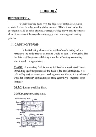
- 1. foundry introduction: Foundry practice deals with the process of making castings in moulds, formed in either sand or either material. This is found to be the cheapest method of metal shaping. Further, castings may be made to fairly close dimensional tolerances by choosing proper moulding and casting process. 1. casting terms: In the following chapters the details of sand-casting, which represents the basic process of casting would be seen. Before going into the details of the process, defining a number of casting vocabulary words would be appropriate. flask: A moulding flask is one which holds the sand mould intact. Depending upon the position of the flask in the mould structure, it is referred by various names such as drag, cope and cheek. It is made up of wood for temporary applications or more generally of metal for long- term use. drag: Lower moulding flask. cope: Upper moulding flask.
- 2. cheek: Intermediate moulding flask used in three-piece moulding. pattern: Pattern is a replica of the final object to be made with some modifications. The mould cavity is made with the help of the pattern. parting line: This is the dividing line between the two moulding flasks that makes up the sand mould. In split pattern it is also the dividing line between the two halves of the pattern. Bottom Board: This is a board normally made of wood, which is used at the start of the mould making. The pattern is first kept on the bottom board, sand is sprinkled on it and then the ramming is done in the drag. facing sand: The small amount of carbonaceous material sprinkled on the inner surface finish to the castings. core: It is used for making hollow cavities in castings. pouring Basin: A small funnel-shaped cavity at the top of the mould into which the molten metal is poured. sprue: The passage through which the molten metal from the pouring basin reaches the mould cavity. In many cases it controls the flow of metal into the mould. runner: The passageways in the parting plane through which molten metal flow is regulated before they reach the mould cavity. gate: The actual entry point through which molten metal enters the mould cavity. chaplet: Chaplets are used to support cores inside the mould cavity to take care of its own weight over-come the metallostatic forces.
- 3. chill: Chills are metallic objects, which are placed in the mould to increase the cooling rate of castings to provide uniform or desired cooling rate. riser: It is a reservoir of molten metal provided in the casting so that hot metal can flow back into the mould cavity when there is a reduction in volume of metal due to solidification. 2. tools: The tools and equipment needed for moulding are: Moulding board, moulding flasks (boxes), shovel and moulders tools. moulding tools: It is a wooden with smooth surface. It supports the flasks and the pattern, while the mould is being made. moulding flask: It is a box, made of wood or metal, open at both ends. The sand is rammed in after placing the pattern to produce a mould. Usually, it is made of two parts. Cope is the top half of the flask, having guides or the aligning pins to enter. Drag is the bottom half of the flask having aligning pins. shovel: It is used for mixing and tempering moulding sand and for transferring the sand into the flask. It is made of steel blade with a wooden handle.
- 4. hammer: It is used or packing or ramming the sand around the pattern. One of its end, called peen end, is wedge shaped and is used for packing sand in spaces, pockets and corners, in early stages of ramming. The other end, called the butt end, has a flat surface and is used for compacting the sand towards the end of moulding. strike off edge: It is a piece of metal or wood with straight edge. It is used to remove the excess sand from the mould after ramming, to provide a level surface. sprue pin:
- 5. It is tapered wooden pin used to make a hole in the cope sand through which the molten metal is poured into the mould. RiseR Pin: It is straight wooden pin used to make a hole in the cope sand, over the mould cavity or the molten metal to rise and feed the casting to compensate the shrinkage that take place during solidification. TRowel: It is used to smoothen the surface of the mould. It may also be used for repairing the damaged portion of the mould. Trowels are made in many different styles and sizes, each one suitable for a particular job. sPike oR DRaw Pin: It is a steel rod with a loop at the other end. It is used to remove the pattern from the mould. A draw Screw, with a threaded end may also be
- 6. used for the purpose to draw metal patterns. silk: It is a small double ended tool having a flat on one end and a spoon on the other. It is used for mending and finishing small surfaces of the mould. lifTeRs: Lifters are made of thin sections of steel of various widths and lengths, with one end bent at right angles. These are used for cleaning and finishing the bottom and sides of the deep and narrow pockets of the mould. GaTe CuTTeR: It is a semi- circular piece of tin sheet, used to cut gates in the mould. Gates are meant for easy flow of molten metal into the mould. Bellows: It is a hand tool, used to blow air to remove the loose sand particles from the mould cavity. VenT RoD:
- 7. It is a thin rod used for making vents or holes in the sand mould to allow the escape of mould gases generated during the pouring of molten metal. CoRe Box: A core box is designed to mould cores. It is made of either wood or metal, into which core sand is packed to form the core. Wood is commonly used for making a core box, but metal boxes are used when cores are to be made in large numbers. Specially prepared core sand is used in making cores. 3. sanD MoulD MakinG PRoCeDuRe: The procedure for making a typical sand mould is described in the following steps. First, a bottom board is placed either on the moulding platform or on the floor, making the surface even. The drag moulding flask is kept upside down on the bottom board along with the drag part of the pattern at the centre of the flask on the board. There should be enough clearance between the pattern and the walls of the flask which should be of the order of 50 to 100mm. Dry facing sand is sprinkled over the board and pattern to provide a non-sticky layer. Freshly prepared moulding sand of requisite quality is now poured into the drag and on the pattern to a thickness of 30 to 50mm. The rest of the drag flask is completely filled with the backup sand and uniformly rammed to compact the sand. The ramming of the sand should be done properly so as not to compact it too hard, which makes the escape of gases difficult, nor too loose, so that the mould would not have enough strength. After the ramming is over, the excess sand in the flask is completely scraped using a flat bar to the level of the flask edges. Now, with a vent wire, which is a wire of 1- to 2-mm diameter with a pointed end, vent holes are made in the drag to the full depth of the flask
- 8. as well as to the pattern to facilitate the removal of gases during casting solidification. This completes the preparation of the drag. The finished drag flask is now rolled over to the bottom board exposing the pattern. Using a slick, the edges of sand around the pattern is repaired and the cope half of the pattern is placed over the drag pattern, aligning it with the help of dowel pins. The cope flask on top of the drag is located aligning again with the help of the pins. The dry parting sand is sprinkled all over the drag and on the pattern. A sprue pin for making the sprue passage is located at a small distance of about 50 mm from the pattern. Also, a riser pin if required is kept at an appropriate place and freshly prepared moulding sand similar to that of the drag along with the backing sand is sprinkled. The sand is thoroughly rammed, excess and scraped and vent holes are made all over in the cope as in the drag. The sprue pin and riser pin are carefully withdrawn from the flask. Later, the pouring basin is cut near the top of the sprue. The cope is separated from the drag and any loose sand on the cope and drag interface of the drag is blown off with the help of bellows. Now, the cope and the drag pattern halves are withdrawn by using the draw spikes and rapping the pattern all around to slightly enlarge the mould cavity so that the mould walls are not spoiled by the withdrawing pattern. The runners and the gates are cut in the mould care-fully without spoiling the mould. Any excess or loose sand found in the runners and mould cavity is blown away the bellows. Now, the facing sand in the form of a paste is applied all over the mould cavity and runners, which would give the finished casting a good surface finish. 4. TyPes of sanD MoulDs: In order to produce sound castings, moulds are required to have some specific properties. Some of them are the following:
- 9. It must be strong enough to withstand the temperature and weight of the molten metal. It must resist the erosive action of the flowing hot metal. It should generate minimum amount of gases as a result of the temperature of the molten metal. It should have good venting capacity to allow the generated gases to completely escape from it. Moulds that are used for sand casting may broadly be classified as Green sand moulds Dry sand moulds Skin dried moulds Green SAnD MOULDS: Green sand is the moulding sand which has been freshly prepared from silica grains, clay and moisture. In a green sand mould, metal is poured immediately and the castings taken out. These are most commonly used and are adapted for rapid production, whereas the moulding flasks are released quickly. Dry SAnD MOULDS: These are the green sand moulds which are completely dried by keeping in an oven between 150 to 350c for 8 to 48 hours depending on the binders in the moulding sand. These moulds generally have higher strengths than the green sand mould and are preferred because they are less likely to be damaged during handling. Skin DrieD MOULD: Though the dry sand mould is preferable for large moulds because of the expense involved, a compromise is achieved by drying only the skin of the mould cavity with which the molten metal comes into
- 10. contact, instead of the full mould. The skin is normally dried to a depth of 15 to 25 mm, using either torches or by simply allowing them to dry in atmosphere. 5. Other SAnDS: Though moulding sands are the prime mould materials used in a foundry, there are a number of other materials, which are also used for a number of specific properties. fAcinG SAnD: This sand is used next to the pattern to obtain cleaner and smoother casting surfaces. Generally, sea coal or coal dust(finely divided bituminous coal of 2 to 8%) is mixed with the system sand to improve the mouldability and surface finish. The sea coal being carbonaceous, will slowly burn due to heat from the molten metal and give off small amounts of reducing gases. MOULD wASh: Purely carbonaceous materials such as sea coal, finely powdered graphite or proprietary compounds are also applied on to the mould cavity after the pattern is withdrawn. This is called the mould wash and is done by spraying, swabbing or painting in the form of a wet paste. These are used essentially for the following reasons: To prevent metal penetration into the sand grains and thus ensure a good casting finish To avoid mould-metal interaction and prevent sand fusion. For deposing the mould wash, either water or alcohol can be used as a carrier. But because of the problem of getting the water out of the mould, alcohol is preferred as a carrier. The proprietary washes are available in powder, paste or liquid form. The powder needs to be first prepared and applied whereas the paste and liquid can be straightaway applied.
- 11. bAckinG SAnD: This is normally the reconditioned foundry sand is used for ramming the bulk of the moulding flask. The moulding flask is completely filled with backing sand after the pattern is covered with a thin layer of facing sand. Since the casting is not affected to any great extent by the backing sand, it usually contains the burnt facing sand, moulding sand and clay. PArtinG SAnD: This is the material, which is sprinkled on the pattern and to the parting surfaces of the mould halves before they are prepared, to prevent the adherence of the moulding sand. This helps in easy withdrawal of the pattern and easier separation of the cope and drag flasks at parting surface. It is essentially a non-sticky material such as washed silica grains. 5. MOULDinG SAnD PrOPertieS: The properties of moulding sand are dependent to a great extent on a number of variables. The important among them are Sand grain shape and size, Clay type and amount, Moisture content, and Method of preparing sand mould. 6. PAttern: A pattern is the replica of the desired casting, which when packed in a suitable material, produces a cavity called the mould. This cavity when filled with molten metal, produces the desired casting after solidification.
- 12. 7. tyPeS Of PAttern: These are various types of patterns depending upon the complexity of the job, the number of castings required and the moulding procedure adopted. SinGLe Piece PAttern: These are inexpensive and the simplest type of patterns. As the name indicates, they are made of a single piece as shown in fig. This type of pattern is used only in cases where the job is very simple and does not create any withdrawal problems. This pattern is expected to be entirely in the drag. SPLit PAttern Or twO Piece PAttern: This is the most widely used type of pattern for intricate castings. When the contour of the casting makes its withdrawal from the mould difficult, or when the depth of the casting is too high, then the pattern is split into two parts so that one part is in the drag and other in the cope.
- 13. gated pattern: This is an improvement over the simple pattern where the gating and runner system are integral with the pattern. This would eliminate the hand cutting of the runners and gates and help in improving the productivity of a moulder.. cope and drag pattern: These are similar to split patterns. In addition to splitting the pattern, the cope and drag halves of the pattern along with the gating and risering systems are attached separately to the metal or wooden plates along with the alignment pins. They are called the cope and drag patterns. Match plate pattern: These are extensions of the previous type. Here, the cope and drag patterns along with the gating and the risering and mounted on a single matching metal or wooden plate on either side.
- 14. loose piece pattern: This type of pattern is also used when the contour of the part is such that withdrawing the pattern from the mould is not possible. Hence during moulding, the obstructing part of the contour is held as a loose piece by a wire. Follow board pattern: This type of pattern is adopted for those castings where there are some portions, which are structurally weak and if not supported properly are likely to break under the force of ramming. sweep pattern: It is used to sweep the complete casting by means of a plane sweep. These are used for generating large shapes, which are axi-symmetrical or prismatic in nature such as bell-shaped or cylindrical.
- 15. skeleton pattern: A skeleton of the pattern made of strips of wood is used for building and final pattern by packing sand around the skeleton. 8. pattern design: While designing a pattern, the following must be considered. Avoid abrupt changes in cross section. Avoid sharp corners and edges, to enable smooth flow of molten metal. Provide the following pattern allowances. • Shrinkage allowance, to allow for shrinkage when casting cools in the mould. • Slight taper or draft, to allow easy withdrawal of the pattern from the mould. • Machining allowance, to take care of the machining on these surfaces.