IEEE PROJECTS ABSTRACT FOR GPS&GSM-Bus automation system using gsm and gps
•Télécharger en tant que DOC, PDF•
2 j'aime•2,597 vues


Recommandé
Recommandé
Contenu connexe
Tendances
Tendances (20)
Similaire à IEEE PROJECTS ABSTRACT FOR GPS&GSM-Bus automation system using gsm and gps
Similaire à IEEE PROJECTS ABSTRACT FOR GPS&GSM-Bus automation system using gsm and gps (20)
Plus de ASHOKKUMAR RAMAR
Plus de ASHOKKUMAR RAMAR (20)
Dernier
Dernier (20)
IEEE PROJECTS ABSTRACT FOR GPS&GSM-Bus automation system using gsm and gps
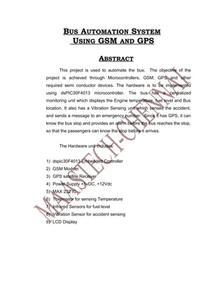
- 1. BUS AUTOMATION SYSTEM USING GSM AND GPS ABSTRACT This project is used to automate the bus. The objective of the project is achieved through Microcontrollers, GSM, GPS and other required semi conductor devices. The hardware is to be implemented using dsPIC30F4013 microcontroller. The bus has a centralized monitoring unit which displays the Engine temperature, fuel level and Bus location. It also has a Vibration Sensing unit which senses the accident, and sends a message to an emergency number. Since it has GPS, it can know the bus stop and provides an alarm before the bus reaches the stop, so that the passengers can know the stop before it arrives. The Hardware unit includes 1) dspic30F4013 Embedded Controller 2) GSM Modem 3) GPS satellite Receiver 4) Power Supply +5vDC, +12Vdc 5) MAX 232 IC 6) Thermistor for sensing Temperature 7) Infrared Sensors for fuel level 8) Vibration Sensor for accident sensing 9) LCD Display
- 2. Block Diagram Fuel LCD Display Level Sensors TTL RS232 GPS Converto r Circuit Dspic Embedded +12V 30F4013 Power Microcontroller Supply RS232 GSM Vibration Potential Sensor Divider Thermistor
- 4. GPS As shown in the above pictures, ProGin SR-92 is a low-power, ultra-high performance, easy to use GPS smart antenna module based on SiRF’s third generation single chip. Its low power consumption and high performance enables the adoption of handheld applications. The slim design allows SR-92 to be placed on top side of the housing to have best GPS signal reception. The 5- pin I/O interface is then connected to the main board with either connector or wire soldering. The integrated antenna design helps reduce the RF and EMI issues to minimum. Fastadoption and high yield production becomes possible. The power control feature is very convenient to turn on/off power via GPIO control pin. It’s especially useful in cases such as to turn off power as the user just wants to watch a movie and GPS function is not needed in the PMP case. Not only handheld but also any other GPS applications can share the following major features of SR-92. _ Easy adoption with best performance _ Integrated antenna and EMC protection _ Built-in backup battery allowing hot/warm starts and better performance _ No external component demand, just connect and use.
- 5. _ Minimum RF and EMI efforts _ Small size of 18 (W) x 21 (L) x 7 (H) (mm) with patch antenna of 25x25x4mm. _ High tracking sensitivity of -159dBm _ Low power consumption of 40mA at full tracking _ Hardware power saving control pin allowing power off GPS via GPIO Thermistor: Thermistor Used to sense the temperature Infrred Sensor: Used to identify the Fuel level Vibration Sensor Used Senses any vibration above certain level Power Supply Provides +5vdc and +12V dc power supply to the units LCD display Used to Display the events MAX232 Used to convert the TTL signal to RS232 level signals
- 6. _ Minimum RF and EMI efforts _ Small size of 18 (W) x 21 (L) x 7 (H) (mm) with patch antenna of 25x25x4mm. _ High tracking sensitivity of -159dBm _ Low power consumption of 40mA at full tracking _ Hardware power saving control pin allowing power off GPS via GPIO Thermistor: Thermistor Used to sense the temperature Infrred Sensor: Used to identify the Fuel level Vibration Sensor Used Senses any vibration above certain level Power Supply Provides +5vdc and +12V dc power supply to the units LCD display Used to Display the events MAX232 Used to convert the TTL signal to RS232 level signals