LATEST IEEE PROJECTS 2012 FOR EEE-EEE PROJECTS ABSTRACT
•Télécharger en tant que DOC, PDF•
1 j'aime•3,582 vues

DEAR STUDENTS, IEEE BASED EMBEDDED SYSTEM PROJECTS(hardware projects)/FINAL YEAR PROJECTS/MINI PROJECTS/DIPLOMA PROJECTS INPLANT TRAINING DETAILS, (ECE/EEE/E&I/CSE/BIOMEDICAL/IT/MECHATRONICS/AYTOMOBILES)&MSC ELECTRONICS.. project details...dont hesitate, pl call me..........,dont hesitate, pl call me.........., thanks R.ASHOK KUMAR MAASTECH 89. RANGARAJAPURAM MAIN ROAD(NEAR SBI BANK) KODAMBAKKAM CHENNAI-600024 PH:044-24844676 ASHOK KUMAR-098402 34766 ipt/projects full details....PL VISIT http://www.maastechindia.com (projects list,abstract,video,photo gallery)

Recommandé
Recommandé
Contenu connexe
Tendances
Tendances (18)
En vedette
En vedette (15)
Similaire à LATEST IEEE PROJECTS 2012 FOR EEE-EEE PROJECTS ABSTRACT
Similaire à LATEST IEEE PROJECTS 2012 FOR EEE-EEE PROJECTS ABSTRACT (20)
Plus de ASHOKKUMAR RAMAR
Plus de ASHOKKUMAR RAMAR (20)
Dernier
Dernier (20)
LATEST IEEE PROJECTS 2012 FOR EEE-EEE PROJECTS ABSTRACT
- 1. Article Information Protection of power transformer using microcontroller-based relay Rafa, A.; Mahmod, S.; Mariun, N.; Hassan, W.Z.W.; Mailah, N.F. Research and Development, 2002. SCOReD 2002. Student Conference on Volume , Issue , 2002 Page(s): 224 - 227 Digital Object Identifier 10.1109/SCORED.2002.1033098 Summary: This paper describes the design and implementation of the micro controller- based system for protecting power transformer. The system includes facilities for discrimination between internal fault current and magnetizing inrush current, differential protection, over current protection, over voltage protection and under voltage protection. In this paper, software and hardware of micro controller based system have been explained and designed. The design implementation and testing of the system are also presented. Fuzzy Logic Based Differential Relay for Power Transformer Protection Need Power Transformers or any CNC Machines or any electrical devices are always subjected to Highvoltage and low voltage transients. Many devices will get failed due to this. Hence we need to monitor the voltage constantly and if goes below or above the range then we need to trip the supply immedieately. One method of protecting power transformers is to use a differential relay. The operation Diff Relay is to trip the equipment if it finds any difference in the primary and secondary current.
- 2. Two basic requirements that the differential-relay connections must satisfy are: (1) The differential relay must not operate for load or external faults; and (2) The relay must operate for severe enough internal faults. This is because the diff relay can act due to the following other factors also. In the case of power transformer applications, possible sources of false differential currents are: Mismatch between the CT ratios and the power transformer ratio Variable ratio of the power transformer caused by a tap changer Phase shift between the power transformer primary and secondary currents Magnetizing inrush currents Transformer overexcitation Current transformer saturation
- 3. So, There should be an intelligent Mechanism to prevent the diff relay from fault triggering. In this project we have employed fuzzy logic to prevent this fault triggering. Our system when detects a current difference between the primary and the secondary it also checks for other causes using fuzzy logic and operates the relay only when essential. The other factors which induces the fault triggering is given to the controller through switch inputs. About Fuzzy: Fuzzy Logic was initiated in 1965 by lofti A. Zadeh, professor for Computer science at the university of California in Berkeley. Fuzzy logic is a powerful new technology and has emerged as a profitable tool for the controlling of subway systems and complex industrial processes, as well as for household and entertainment electronics, diagnosis systems and other expert systems. Although, fuzzy logic was invented in United states the rapid growth of this technology has started from Japan and has now again reached the USA and Europe also. Fuzzy has become a keyword for marketing. Electronic articles without fuzzy component gradually turn out to be a dead stock. As a gag, that shows the popularity of fuzzy logic, there even exists a toilet paper with ‘Fuzzy Logic’ Printed on it. In japan fuzzy-research is widely supported with a huge budget. In Europe and the USA efforts are being made to catch up with the tremendous Japanese success. For instance, the NASA space agency is engaged in applying fuzzy logic for complex docking-maneuvers.
- 4. Fuzzy logic is basically a multivalued logic that allows intermediate values to be defined between conventional evaluations like yes/no, true/false, black/white etc. Notions like rather warm or pretty cold can be formulated mathematically and processed by computers
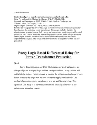
- 5. Block Diagram: Monitor CPU Mismatch between the Rs232 Magnetizi CT ratios and the ng inrush power transformer currents ratio Variable ratio Transformer of the power overexcitatio PIC Microcontroller n transformer Phase shift between Current the power transformer transformer primary saturation and secondary currents Relay Driver Full Wave Precision Full Wave Precision Rectifier Rectifier Differential Relay PT CT PT CT Power Transformer Power Line
- 6. Block Diagram: Monitor CPU Mismatch between the Rs232 Magnetizi CT ratios and the ng inrush power transformer currents ratio Variable ratio Transformer of the power overexcitatio PIC Microcontroller n transformer Phase shift between Current the power transformer transformer primary saturation and secondary currents Relay Driver Full Wave Precision Full Wave Precision Rectifier Rectifier Differential Relay PT CT PT CT Power Transformer Power Line
- 7. Block Diagram: Monitor CPU Mismatch between the Rs232 Magnetizi CT ratios and the ng inrush power transformer currents ratio Variable ratio Transformer of the power overexcitatio PIC Microcontroller n transformer Phase shift between Current the power transformer transformer primary saturation and secondary currents Relay Driver Full Wave Precision Full Wave Precision Rectifier Rectifier Differential Relay PT CT PT CT Power Transformer Power Line
- 8. Block Diagram: Monitor CPU Mismatch between the Rs232 Magnetizi CT ratios and the ng inrush power transformer currents ratio Variable ratio Transformer of the power overexcitatio PIC Microcontroller n transformer Phase shift between Current the power transformer transformer primary saturation and secondary currents Relay Driver Full Wave Precision Full Wave Precision Rectifier Rectifier Differential Relay PT CT PT CT Power Transformer Power Line