
Recommandé
Contenu connexe
En vedette
Dernier
Dernier (20)
Get awesome info about basic electronics here
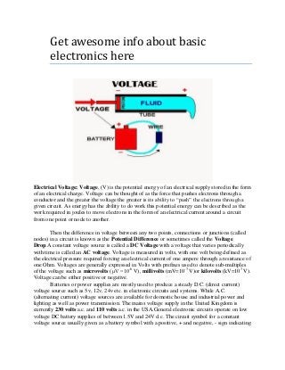
- 1. Get awesome info about basic electronics here Electrical Voltage: Voltage, (V) is the potential energy of an electrical supply stored in the form of an electrical charge. Voltage can be thought of as the force that pushes electrons through a conductor and the greater the voltage the greater is its ability to “push” the electrons through a given circuit. As energy has the ability to do work this potential energy can be described as the work required in joules to move electrons in the form of an electrical current around a circuit from one point or node to another. Then the difference in voltage between any two points, connections or junctions (called nodes) in a circuit is known as the Potential Difference or sometimes called the Voltage Drop.A constant voltage source is called a DC Voltage with a voltage that varies periodically with time is called an AC voltage. Voltage is measured in volts, with one volt being defined as the electrical pressure required forcing an electrical current of one ampere through a resistance of one Ohm. Voltages are generally expressed in Volts with prefixes used to denote sub-multiples of the voltage such as microvolts (μV =10-6 V), millivolts (mV=10-3 V)or kilovolts (kV=103 V). Voltage can be either positive or negative. Batteries or power supplies are mostly used to produce a steady D.C. (direct current) voltage source such as 5v, 12v, 24v etc. in electronic circuits and systems. While A.C. (alternating current) voltage sources are available for domestic house and industrial power and lighting as well as power transmission. The mains voltage supply in the United Kingdom is currently 230 volts a.c. and 110 volts a.c. in the USA.General electronic circuits operate on low voltage DC battery supplies of between 1.5V and 24V d.c. The circuit symbol for a constant voltage source usually given as a battery symbol with a positive, + and negative, - sign indicating
- 2. the direction of the polarity. The circuit symbol for an alternating voltage source is a circle with a sine wave inside. Electrical Current: Current, (I) is the movement or flow of electrical charge and is measured in Amperes. It is the continuous and uniform flow (called a drift) of electrons (the negative particles of an atom) around a circuit that are being “pushed” by the voltage source. In reality, electrons flow from the negative (-ve) terminal to the positive (+ve) terminal of the supply and for ease of circuit understanding conventional current flow assumes that the current flows from the positive to the negative terminal. Conventionally this is the flow of positive charge around a circuit, being positive to negative. The diagram at the left shows the movement of the positive charge (holes) around a closed circuit flowing from the positive terminal of the battery, through the circuit and returns to the negative terminal of the battery. This flow of current from positive to negative is generally known as conventional current flow.The Conventional Current Flow gives the flow of electrical current from positive to negative and which is the opposite in direction to the actual flow of electrons.The flow of electrons around the circuit is opposite to the direction of the conventional current flow being negative to positive.The actual current flowing in an electrical circuit is composed of electrons that flow from the negative pole of the battery (the cathode) and return back to the positive pole (the anode) of the battery. This is because the charge on an electron is negative by definition and so is attracted to the positive terminal. This flow of electrons is called Electron Current Flow. Therefore, electrons actually flow around a circuit from the negative terminal to the positive.Both conventional current flow and electron flow are used by many textbooks. In fact, it makes no difference which way the current is flowing around the circuit as long as the direction is used consistently. The direction of current flow does not affect what the current does within the circuit. Generally it is much easier to understand the conventional current flow – positive to negative. In electronic circuits, a current source is a circuit element that provides a specified amount of current for example, 1A, 5A 10 Amps etc., with the circuit symbol for a constant current source given as a circle with an arrow inside indicating its direction.Current is measured in Amps and an amp or ampere is defined as the number of electrons or charge (Q in Coulombs) passing a certain point in the circuit in one second, (t in Seconds).Electrical current is generally expressed in Amps with prefixes used to denote micro amps (μA=10-6 A) or milliamps (mA=10- 3 A). Note that electrical current can be either positive in value or negative in value depending upon its direction of flow. Current that flows in a single direction is called Direct Current, or D.C. and current that alternates back and forth through the circuit is known asAlternating Current. Whether AC or DC current only flows through a circuit when a voltage source is connected to it with its “flow” being limited to both the resistance of the circuit and the voltage source pushing it.Also, as alternating currents (and voltages) are periodic and vary with time the “effective” or “RMS”, (Root Mean Squared) value given as Irms produces the same average power loss equivalent to a DC current Iavg. Current sources are the opposite to voltage sources in that they like short or closed circuit conditions but hate open circuit conditions as no current will flow. Using the tank of water relationship, current is the equivalent of the flow of water through the pipe with the flow being the same throughout the pipe. The faster the flow of water the greater the current. Any current source whether DC or AC likes a short or semi-short circuit condition but hates any open circuit condition as this prevents it from flowing.
- 3. Resistance: Resistance, (R) of a circuit is its ability to resist or prevent the flow of current (electron flow) through itself making it necessary to apply a greater voltage to the electrical circuit to cause the current to flow again. Resistance is measured in Ohms, Greek symbol (Ω, Omega)with prefixes used to denote Kilo-ohms (kΩ=103 Ω) and Mega-ohms (MΩ=106 Ω). Note that Resistance cannot be negative in value only positive.The amount of resistance determines whether the circuit is a “good conductor” – low resistance, or a “bad conductor” – high resistance. Low resistance, for example 1Ω or less implies that the circuit is a good conductor made from materials such as copper, aluminium or carbon while a high resistance, 1MΩ or more implies the circuit is a bad conductor made from insulating materials such as glass, porcelain or plastic. Resistance can be linear in nature or non-linear in nature. Linear resistance obeys Ohm’s Law and controls or limits the amount of current flowing within a circuit in proportion to the voltage supply connected to it and therefore the transfer of power to the load. Non-linear resistance does not obey Ohm’s Law but has a voltage drop across it that is proportional to some power of the current.Resistance is pure and is not affected by frequency with the AC impedance of a resistance being equal to its DC resistance and as a result can’t be negative. Remember that resistance is always positive, and never negative. Resistance can also be classed as an attenuator as it has the ability to change the characteristics of a circuit by the effect of loading the circuit or by temperature which changes its resistivity. For very low values of resistance, for example milliohms, (mΩ) it is sometimes much easier to use the reciprocal of resistance (1/R) rather than resistance (R) itself. The reciprocal of resistance is called Conductance, symbol (G) and represents the ability of a conductor or device to conduct electricity.High values of conductance imply a good conductor such as copper while low values of conductance implies a bad conductor such as wood. The standard unit of measurement given for conductance is the Siemen, symbol (S).Again, using the water relationship, resistance is the diameter or the length of the pipe the water flows through. The small diameter of the pipe has larger resistance to the flow of water, and therefore the large resistance. Ohm's Law is a formulation of the relationship of voltage, current, and resistance, expressed as: V=I*R;I=V/R;R=V/I. Hence, Volt= Amps times Resistance Capacitors: Capacitors derive their name from their capacity to store charge, and are used in a circuit to damp out rapid changes in voltage. They consist of two conducting surfaces separated by an insulator (the 'dielectric'), with a lead connected to each surface. To create the values of capacitance needed for practical circuits, one needs conducting surfaces which are both very large and very close together, and separated by a material with a high 'dielectric constant'. To pack sufficient surface area into a small volume, capacitors usually have a rolled or stacked internal structure. If a constant voltage is applied to a capacitor, only a very small 'leakage current' will flow once the capacitor has fully charged. Inductors: Inductorsare coils of wire with many turns, often wound around a core made of a magnetic material, like iron or ferrite. Current flowing through the inductor produces a local magnetic field in which energy is stored. This field creates an induced current in the inductor in a direction which resists any change in the current flowing in the circuit. Inductors are thus used in circuits to prevent any rapid changes in current. Quantity Symbol Unit of Abbreviation
- 4. Measure Voltage V or E Volt V Current I Ampere A Resistance R Ohms Ω Inductance L Henry H Capacitance C Farad F Also read : How to form a PN Junction by using semiconductor Easy to learn PN Junction Diode How does pn junction works in diode 5 things you need to know about analysis and overview of pn junction diode