
Recommandé
Recommandé
Contenu connexe
Tendances
Tendances (20)
Similaire à Tutorial caesars II
Similaire à Tutorial caesars II (20)
Tutorial caesars II
- 1. May 2002 Dear CAESAR II User, Enclosed please find Version 4.40 of the CAESAR II Pipe Stress Analysis program. This package includes a CD-Rom and associated documentation. This version of CAESAR II incorporates a number of new features and technical capabilities, some of which are listed in the table below (for a complete list of changes, refer to Chapter 1 of the User’s Guide). • Piping codes: revised B31.3, B31.4, B31.5, B31.8, ASME NC, ASME ND; added B31.11. • An alpha-numeric node label option has been added to the piping input module • Expanded Static Load case options: (1) added load components H, CS, HP, and WW (hanger loads, cold spring, hydro pressure, and weight filled with water, respectively), (2) added HYDRO stress type, (3) added option to set snubber and hanger status on a load case basis, (4) provided ability to scale friction factor on a load case basis. • Added automatic generation of a hydrotest load case (WW+HP, HYD stress type, and spring hangers locked), triggered by the presence of a non-zero HP. • A large number of updates have been made to the 3D input graphics, as well as partial implementation in the static output processor (including the “Element Viewer”). • Updated the spring hanger design algorithm to provide the option to iterate the “Operating for Hanger Travel” load case to include the stiffness of the selected hanger. • Added new configuration options for ambient temperature, default friction coefficient, liberal stress allowable, stress stiffening, and Bourdon settings, as well as how to handle B16.9 welding tee and sweepolet SIFs in B31.3. • Two new spring hanger tables have been added: Pipe Supports USA and Quality Pipe Supports. • Included piping and structural files now support long file names, may be located in any directory path, and the number of included structural files has been expanded from 10 to 20. The CD-ROM has an Auto-Run feature that should start the installation driver as soon as the CD tray is closed. This installation driver includes a number of options, in addition to the installation of Version 4.40. The installation of Version 4.40 will create a group on the startup menu for subsequent access. Additionally a desktop shortcut icon to C2.EXE will be placed on the desktop. Please refer to Chapter 2 of the User’s Manual for additional details. Please be aware that Version 4.40 is not downward compatible with any previous version of the software. Input files from older versions are upward compatible as always. Version 4.40 (like all previous versions) of CAESAR II has been tested according to the QA standards established at COADE. Jobs created on earlier versions are compatible with Version 4.40 and should yield the same results as earlier versions (except as noted in the Technical Changes on the next page). Regards, CAESAR II Development Staff
- 3. CAESAR II Version 4.40 Changes • Revised piping codes: B31.3, B31.4, B31.5, B31.8, ASME NC, ASME ND • Added the B31.11 piping code. • Added an alpha-numeric node label option to the piping input module • Expanded Static Load case options: (1) added load components H, CS, HP, and WW (hanger loads, cold spring, hydro pressure, and weight filled with water, respectively), (2) added HYDRO stress type, (3) added option to set snubber and hanger status on a load case basis, (4) provided ability to scale friction factor on a load case basis. • Added automatic generation of a hydrotest load case (WW+HP, HYD stress type, and spring hangers locked), triggered by the presence of a non-zero HP. • Added a large number of updates to the 3D input graphics, as well as partial implementation in the static output processor (including the “Element Viewer”). • Updated the spring hanger design algorithm to provide the option to iterate the “Operating for Hanger Travel” load case to include the stiffness of the selected hanger. • Added new configuration options for ambient temperature, default friction coefficient (if non-zero, automatically gets applied to new translational restraints), liberal stress allowable, stress stiffening, and Bourdon settings, as well as how to handle B16.9 welding tee and sweepolet SIFs in B31.3. • Added two new spring manufacturers tables Pipe Supports USA and Quality Pipe Supports. • Added the ability to define the flexibility factor on bends. • Included piping and structural files now support long file names, may be located in any directory path, and the number of included structural files has been expanded from 10 to 20. • Results of the Hanger Design Cases are now optionally viewable in the Static Output Processor (set status to “KEEP” in the Load Case Options). • Added the ability to filter static Restraint reports by CNODE status. • Added a new “warning report” to the static output. • Added a “dirty flag” has been added to the piping input preprocessor and the configuration modules. Attempting to exit these processors without saving changes produces a warning message. • Differences between material data in the input file and that in the material database (including missing “user materials”) are now detected, offering the user the opportunity to use the original data. • Reviewed/updated the “minimum wall” computation for all piping codes for straight pipe. • Added a field for specifying “Marine Growth Density” to the Wind/Wave dialog.
- 4. • Updated API-661 to 4th Edition. • Added the ability to save static load case data without running the job. CAESAR II VERSION 4.40 - TECHNICAL CHANGES The following list details changes to CAESAR II for Version 4.40, which may affect the numeric results. • In the “flange module”, a change has been made in where Peq is applied. Previously, Peq was used everywhere the pressure term was included in an equation. As of Version 4.40, Peq is only applied to the computation of “H”. The design pressure is applied to the computation of “HT” and “HD”. • The A01 (2001) addendum to B31.3 exchanged the equations (between the figure and the notes) used to compute the "flexibility characteristic" for welding tees and welded-in contour inserts (sweepolets). This change will cause the SIFs for these fittings to change accordingly. CAESAR II defaults to the updated equation in the figure, which is more conservative. Users can control this choice with a new configuration option. • In the ambient field of the “Special Execution Options” tab, a temperature value entered as zero is now assumed to be zero, instead of ambient. • The “Bergen” and “Fronek” spring hanger data files have been updated to comply with new hardware supplied by these vendors. Existing jobs using these hanger databases may yield slightly different results • Cold Spring and Spring Hanger loads are no longer components of “concentrated force vector #1 (F1), as they were in previous versions. These loads are now represented by “CS” and “H” in the load case definitions. • The static load case editor no longer recommends load cases with “F1”. This is because spring hanger preloads and cold spring have now been separated from this basic load component. It is up to the user to include F1, if present, in the appropriate load cases. • For B31.3 and NAVY505 piping codes, the software has been changed so that allowable stresses are no longer divided by the joint efficiency. (This should not present many problems, since division by the joint efficiency has not been required for the B31.3 code since 1980.) This change was necessary in order to properly perform the minimum wall thickness calculation. • The minimum wall thickness computation has been reviewed for each piping code supported by CAESAR II. Adjustments have been made where appropriate (B31.3, B31.4, B31.8, BS806, CODETI). • Mill tolerance is now considered in Stoomwezen jobs and B31.8 Ch VIII jobs. (In the case of B31.8 Ch VIII, mill tolerance only affects the combined stress calculation.) • Allowable stresses are now given for BS-7159 and UKOOA for the Sustained and Occasional load cases. These are identical to the Operating allowables. • Spring Hanger Algorithm Update: The spring hanger design algorithm has been improved to repeat (iterate) the “free thermal” design load case in the event poor hanger locations result in “zero load hangers”. The improved algorithm also accounts for frictional effects in the iteration scheme.
- 5. • For analyses using the B31.8 piping code, an additional (OPE) load case is recommended as the absolute sum of the Expansion and Sustained load cases. This additional load case better reflects the intent of section 833.4 of the code. • A change was made as to how local forces are computed in combination cases. Prior to 4.40, global forces were rotated to obtain local forces. Now, in combination cases, local forces in combination cases are combined directly. This change may affect combination methods of Scalar, SRSS, and ABS.
- 7. CAESAR II, VERSION 4.40 Copyright(c) COADE/Engineering Physics Software, Inc., 1984-2002, all rights reserved. (LAST REVISED 5/2002)
- 8. This page is intentionally left blank.
- 9. CAESAR II - User’s Guide Table of Contents 3UHIDFH 3 CAESAR II LICENSE AGREEMENT P-2 ACCEPTANCE OF TERMS OF AGREEMENT BY THE USER P-2 LICENSE GRANT P-2 TERM P-2 LIMITED WARRANTY P-3 ENTIRE AGREEMENT P-3 LIMITATIONS OF REMEDIES P-3 GENERAL P-4 DISCLAIMER - CAESAR II P-4 HOOPS‘ License Grant P-5 ,QWURGXFWLRQ What is CAESAR II? 1-2 What are the applications of CAESAR II? 1-2 What distinguishes CAESAR II from other commercial pipe stress packages? 1-3 About the CAESAR II Documentation 1-4 Program Support/User Assistance 1-5 Software Revision Procedures 1-6 How Are Builds Identified? 1-6 Can Builds Be Applied to Any Version? 1-6 How Are Builds Announced? 1-7 How Are Builds Obtained? 1-7 What is Contained in a Specific Build? 1-7 How Are Builds Installed? 1-7 How Can Builds Be Detected/Checked? 1-7 How Do You Archive and Reinstall an Old, Patched Version? 1-8 Updates and License Types 1-9 Full Run 1-9 Lease 1-9 Limited Run 1-9 Summary of the Latest Program Improvements 1-10 CAESAR II Technical Changes 1-11 ,QVWDOODWLRQ 8 Overview U2-2 System and Hardware Requirements U2-3 Installation Menu Options U2-4 CAESAR II Version 4.40 U2-4 Installation Process U2-4 Checking the Installation U2-12 1
- 10. CAESAR II - User’s Guide Configuration U2-12 Browse CD ROM U2-15 ODBC Drivers U2-15 Product Demos U2-16 Internet Explorer U2-16 ESL Drivers U2-17 Contact Information U2-18 Product Information U2-19 Exit U2-19 ESL Installation on a Network U2-20 Novell File Server ESL Installation U2-20 Novell Workstation ESL Installation U2-20 Windows server Installation U2-20 Notes on Network ESLs U2-21 Re-Enabling the AutoRun Feature U2-22 4XLFN 6WDUW DQG %DVLF 2SHUDWLRQ 8 CAESAR II Quick Start U3-2 Starting CAESAR II U3-2 Basic Operation U3-5 Piping Input Generation U3-5 Error Checking the Model U3-10 Building the Load Cases U3-11 Executing Static Analysis U3-13 Static Output Review U3-14 0DLQ 0HQX 8 The CAESAR II Main Menu U4-2 File Menu U4-3 Input Menu U4-5 Analysis Menu U4-6 Output Menu U4-7 Tools Menu U4-8 Diagnostics Menu U4-9 ESL Menu U4-10 Help Menu U4-11 3LSLQJ ,QSXW 8 Spreadsheet Overview U5-2 Undo/Redo U5-2 Customize Toolbar U5-3 Data Fields U5-3 Node Numbers U5-3 2
- 11. CAESAR II - User’s Guide Element Lengths U5-4 Element Direction Cosines U5-4 Pipe Section Properties U5-5 Operating Conditions: Temperatures and Pressures U5-5 Special Element Information U5-6 Boundary Conditions U5-7 Loading Conditions U5-7 Piping Material U5-8 Material Elastic Properties U5-8 Densities U5-8 Auxiliary Data Area U5-9 Bend Data U5-9 Rigid Weight U5-10 Expansion Joint U5-10 Restraints U5-11 Displacements U5-12 Forces U5-13 Uniform Loads U5-13 Wind/Wave U5-14 Allowable Stresses U5-15 Stress Intensification Factors/Tees U5-18 Flexible Nozzles U5-19 Hangers U5-20 Node Names U5-21 Offsets U5-21 Menu Commands U5-22 File Menu U5-22 Edit Menu U5-24 Model Menu U5-27 Kaux Menu U5-32 Plot U5-36 Alternative 3-D Graphics U5-39 (UURU KHFNLQJ 6WDWLF /RDG DVHV DQG $QDOVLV 8 Error Checking U6-2 Fatal Error Dialog U6-3 Warning Dialog U6-4 Note Dialog U6-5 Available Commands U6-5 Building Static Load Cases U6-7 Providing Wind Data U6-9 Specifying Hydrodynamic Parameters U6-11 Execution of Static Analysis U6-12 Notes on CAESAR II Load Cases U6-16 Definition of a Load Case U6-16 Load Case Options Tab U6-21 3
- 12. CAESAR II - User’s Guide User Control of Produced Results Data U6-22 Output Status U6-22 Output Type U6-22 Snubbers Active? U6-23 Hanger Design U6-23 Friction Multiplier U6-23 User-Controlled Combination Methods U6-24 Algebraic U6-24 Scalar U6-24 SRSS U6-24 ABS U6-25 Max U6-25 Min U6-25 SignMax U6-25 SignMin U6-25 Recommended Load Cases U6-26 Recommended Load Cases for Hanger Selection U6-26 6WDWLF 2XWSXW 3URFHVVRU 8 Entry Into the Static Output Processor U7-2 Report Options U7-6 Displacements U7-6 Restraints U7-6 Restraint Summary U7-7 Global Element Forces U7-7 Local Element Forces U7-8 Stresses U7-9 Sorted Stresses U7-10 Code Compliance Report U7-11 U7-11 Cumulative Usage Report U7-12 U7-12 Load Case Report U7-13 Notes on Printing or Saving Reports to a File U7-14 Notes on Plotting Static Results U7-16 “SHOWing” Results on the Plot U7-17 Main Show Menu U7-17 Displacement Sub Menu: U7-17 Restraints Sub Menu: U7-18 Forces/Moments Sub Menu: U7-18 Stress Sub Menu: U7-20 Notes on Animation of Static Results U7-21 4
- 13. CAESAR II - User’s Guide 'QDPLF ,QSXW DQG $QDOVLV 8 Dynamic Capabilities in CAESAR II U8-2 Model Modifications for Dynamic Analysis U8-3 Major Steps in Dynamics Input U8-5 Overview of the Dynamic Analysis Input Processor U8-6 Entering the Dynamic Analysis Input Menu U8-6 Input Overview Based on Analysis Category U8-9 Modal U8-9 Specifying the Loads U8-9 Snubbers U8-10 Control Parameters U8-10 Advanced Parameters Show Screen U8-10 Harmonic U8-11 Specifying the Loads U8-11 Modifying Mass and Stiffness Model U8-13 Control Parameters U8-13 Earthquake (Spectrum) U8-14 Specifying the Loads U8-14 Spectrum Load Cases U8-16 Static/Dynamic Combinations U8-18 Modifying Mass and Stiffness Model U8-19 Control Parameters U8-19 Advanced Parameters U8-19 Relief Loads (Spectrum) U8-20 Specifying the Loads U8-20 Relief Load Synthesis U8-20 Pulse Table/DLF Spectrum Generation U8-21 Spectrum Definitions U8-23 Force Sets U8-24 Spectrum/Load Cases U8-25 Static/Dynamic Combinations U8-26 Modifying Mass and Stiffness Model U8-26 Control Parameters U8-26 Advanced U8-27 Water Hammer/Slug Flow (Spectrum) U8-28 Specifying the Load U8-28 Pulse Table/DLF Spectrum Generation U8-28 Spectrum Definitions U8-28 Force Sets U8-28 Spectrum Load Cases U8-28 Static/Dynamic Combinations U8-28 Modifying Mass and Stiffness Model U8-28 Time History U8-29 Specifying The Load U8-29 Time History Profile Definitions U8-29 Force Sets U8-30 Time History Load Cases U8-31 5
- 14. CAESAR II - User’s Guide Static/Dynamic Combinations U8-31 Modifying Mass and Stiffness Models U8-31 Control Parameters U8-31 Advanced U8-32 Error Handling and Analyzing the Job U8-33 Performing the Analysis U8-33 Modes U8-33 Harmonic U8-34 Selection of Phase Angles U8-34 Spectrum U8-35 Time History U8-35 'QDPLF 2XWSXW 3URFHVVLQJ 8 Entry into the Processor U9-2 Report Types U9-5 Displacements U9-5 Restraints U9-5 Local Forces U9-6 Global Forces U9-7 Stresses U9-7 Forces/Stresses U9-8 Cumulative Usage U9-8 Mass Participation Factors U9-9 Natural Frequencies U9-10 Modes Mass Normalized U9-10 Modes Unity Normalized U9-10 Included Mass Data U9-11 Input Listing U9-12 Mass Model U9-12 Boundary Conditions U9-12 Notes on Printing or Saving Reports to a File U9-13 Animation of Dynamic Results U9-14 CASE U9-18 PRINT MOTION U9-18 6WUXFWXUDO 6WHHO 0RGHOLQJ 8 Overview of Structural Capability in CAESAR II U10-2 Sample Input U10-9 Structural Steel Example #1 U10-9 Structural Steel Example #2 U10-13 Structural Steel Example #3 U10-25 6
- 15. CAESAR II - User’s Guide %XULHG 3LSH 0RGHOLQJ 8 CAESAR II Underground Pipe Modeler U11-2 Using the Underground Pipe Modeler U11-3 Notes on the Soil Model U11-10 Recommended Procedures U11-13 Buried Pipe Example U11-14 (TXLSPHQW DQG RPSRQHQW RPSOLDQFH 8 Equipment and Component Evaluation U12-2 Intersection Stress Intensification Factors U12-3 Bend Stress Intensification Factors U12-5 Pressure Stiffening U12-6 Flanges Attached to Bend Ends U12-6 Bends with Trunnions U12-7 Stress Concentrations and Intensifications U12-7 WRC 107 (Vessel Stresses) U12-8 WRC 107 Stress Summations U12-14 WRC Bulletin 297 U12-16 Flange Leakage/Stress Calculations U12-19 Note on bolt tightening stress U12-23 Using the CAESAR II Flange Modeler U12-24 Leak Pressure Ratio U12-24 Effective Gasket Modulus U12-24 Flange Rating U12-24 Remaining Strength of Corroded Pipelines, B31G U12-28 Expansion Joint Rating U12-33 Structural Steel Checks - AISC U12-40 Global Parameters U12-40 Structural Code U12-41 Allowable Stress Increase Factor U12-41 Stress Reduction Factors Cmy and Cmz U12-42 Young’s Modulus U12-42 Material Yield Strength U12-42 Bending Coefficient U12-42 Form Factor Qa U12-42 Allow Sidesway U12-42 Resize Members Whose Unity Check Value Is . . . U12-43 Minimum Desired Unity Check U12-43 Maximum Desired Unity Check U12-43 Local Member Data U12-44 Member Start Node U12-44 Member End Node U12-44 7
- 16. CAESAR II - User’s Guide Member Type U12-44 In- And Out-Of-Plane Fixity Coefficients Ky And Kz U12-46 Unsupported Axial Length U12-46 Unsupported Length (In-Plane Bending) U12-46 Unsupported Length (Out-Of-Plane Bending) U12-46 Double Angle Spacing U12-46 Young’s Modulus U12-46 Material Yield Strength U12-46 Axial Member Force U12-46 In-Plane Bending Moment U12-47 Out-of-Plane Bending Moment U12-47 In-Plane “Small” Bending Moment U12-47 In-Plane “Large” Bending Moment U12-47 Out-of-Plane “Small” Bending Moment U12-47 Out-of-Plane “Large” Bending Moment U12-47 AISC Output Reports U12-47 Differences Between the 1977 and 1989 AISC Codes U12-49 NEMA SM23 (Steam Turbines) U12-50 NEMA Turbine Example U12-51 API 610 (Centrifugal Pumps) U12-57 Vertical In-Line Pumps U12-63 API 617 (Centrifugal Compressors) U12-64 API 661 (Air Cooled Heat Exchangers) U12-66 Heat Exchange Institute Standard For Closed Feedwater Heaters U12-71 API 560 (Fired Heaters for General Refinery Services) U12-73 8
- 17. 3UHIDFH 7KH 3UHIDFH SURYLGHV LPSRUWDQW OHJDO LQIRUPDWLRQ IRU $(6$5 ,, XVHUV RQWHQWV $FFHSWDQFH RI 7HUPV RI $JUHHPHQW E WKH 8VHU /LFHQVH *UDQW 7HUP /LPLWHG :DUUDQW (QWLUH $JUHHPHQW /LPLWDWLRQV RI 5HPHGLHV *HQHUDO 'LVFODLPHU +2236 /LFHQVH *UDQW
- 18. CAESAR II LICENSE AGREEMENT CAESAR II - User’s Guide CAESAR II LICENSE AGREEMENT Licensor: COADE/Engineering Physics Software, Inc., 12777 Jones Rd., Ste. 480, Hous- ton, Texas 77070 ACCEPTANCE OF TERMS OF AGREEMENT BY THE USER YOU SHOULD CAREFULLY READ THE FOLLOWING TERMS AND CONDITIONS BEFORE USING THIS PACKAGE. USING THIS PACKAGE INDICATES YOUR ACCEPTANCE OF THESE TERMS AND CONDITIONS. The enclosed proprietary encoded materials, hereinafter referred to as the Licensed Pro- gram(s), are the property of COADE and are provided to you under the terms and condi- tions of this License Agreement. You assume responsibility for the selection of the appropriate Licensed Program(s) to achieve the intended results, and for the installation, use and results obtained from the selected Licensed Program(s). LICENSE GRANT In return for the payment of the license fee associated with the acquisition of the Licensed Program(s) from COADE, COADE hereby grants you the following non-exclusive rights with regard to the Licensed Programs(s): a. Use of the License Program(s) on one machine. Under no circumstance is the License Program to be executed without a COADE External Software Lock (ESL). b. To transfer the Licensed Program(s) and license it to a third party if the third party acknowledges in writing its agreement to accept the Licensed Program(s) under the terms and conditions of this License Agreement; if you transfer the Licensed Program(s), you must at the same time either transfer all copies whether printed or in machine-readable form to the same party or destroy any copies not so trans- ferred; the requirement to transfer and/or destroy copies of the Licensed Pro- gram(s) also pertains to any and all modifications and portions of Licensed Program(s) contained or merged into other programs. You agree to reproduce and include the copyright notice as it appears on the Licensed Pro- gram(s) on any copy, modification or merged portion of the Licensed Program(s). THIS LICENSE DOES NOT GIVE YOU ANY RIGHT TO USE COPY, MODIFY, OR TRANSFER THE LICENSED PROGRAM(S) OR ANY COPY, MODIFICATION OR MERGED PORTION THEREOF, IN WHOLE OR IN PART, EXCEPT AS EXPRESSLY PROVIDED IN THIS LICENSE AGREEMENT. IF YOU TRANSFER POSSESSION OF ANY COPY, MODIFICATION OR MERGED PORTION OF THE LICENSED PROGRAM(S) TO ANOTHER PARTY, THE LICENSE GRANTED HEREUNDER TO YOU IS AUTOMATICALLY TERMINATED. TERM This License Agreement is effective upon acceptance and use of the Licensed Program(s) until terminated in accordance with the terms of this License Agreement. You may termi- nate the License Agreement at any time by destroying the Licensed Program(s) together with all copies, modifications, and merged portions thereof in any form. This License Agreement will also terminate upon conditions set forth elsewhere in this Agreement or automatically in the event you fail to comply with any term or condition of this License 2 Preface
- 19. CAESAR II - User’s Guide CAESAR II LICENSE AGREEMENT Agreement. You hereby agree upon such termination to destroy the Licensed Program(s) together with all copies, modifications, and merged portions thereof in any form. LIMITED WARRANTY The Licensed Program(s), i.e. the tangible proprietary software, is provided “AS IS” WITHOUT WARRANTY OF ANY KIND, EITHER EXPRESSED OR IMPLIED, AND EXPLICITLY EXCLUDING ANY IMPLIED WARRANTIES OF MERCHANTABIL- ITY OR FITNESS FOR A PARTICULAR PURPOSE. The entire risk as to the quality and performance of the Licensed Program(s) is with you. Some jurisdictions do not allow the exclusion of limited warranties, and, in those jurisdic- tions the above exclusions may not apply. This Limited Warranty gives you specific legal rights, and you may also have other rights which vary from one jurisdiction to another. COADE does not warrant that the functions contained in the Licensed Program(s) will meet your requirements or that the operation of the program will be uninterrupted or error free. COADE does warrant, however, that the CD(s), i.e. the tangible physical medium on which the Licensed Program(s) is furnished, to be free from defects in materials and work- manship under normal use for a period of ninety (90) days from the date of delivery to you as evidenced by a copy of your receipt. COADE warrants that any program errors will be fixed by COADE, at COADE’s expense, as soon as possible after the problem is reported and verified. However, only those cus- tomers current on their update/maintenance contracts are eligible to receive the corrected version of the program. ENTIRE AGREEMENT This written Agreement constitutes the entire agreement between the parties concerning the Licensed Program(s). No agent, distributor, salesman or other person acting or repre- senting themselves to act on behalf of COADE has the authority to modify or supplement the limited warranty contained herein, nor any of the other specific provisions of this Agreement, and no such modifications or supplements shall be effective unless agreed to in writing by an officer of COADE having authority to act on behalf of COADE in this regard. LIMITATIONS OF REMEDIES COADE’s entire liability and your exclusive remedy shall be: a. the replacement of any CD not meeting COADE’s “Limited Warranty” as defined herein and which is returned to COADE or an authorized COADE dealer with a copy of your receipt, or b. if COADE or the dealer is unable to deliver a replacement CD which is free of defects in materials or workmanship you may terminate this License Agreement by returning the Licensed Program(s) and associated documentation and you will be refunded all monies paid to COADE to acquire the Licensed Program(s). IN NO EVENT WILL COADE BE LIABLE TO YOU FOR ANY DAMAGES, INCLUDING ANY LOST PROFITS, LOST SAVINGS, AND OTHER INCIDENTAL Preface 3
- 20. CAESAR II - User’s Guide CAESAR II LICENSE AGREEMENT OR CONSEQUENTIAL DAMAGES ARISING OUT OF THE USE OR INABILITY TO USE THE LICENSED PROGRAM(S) EVEN IF COADE OR AN AUTHORIZED COADE DEALER HAS BEEN ADVISED OF THE POSSIBILITY OF SUCH DAM- AGES, OR FOR ANY CLAIM BY ANY OTHER PARTY. SOME JURISDICTIONS DO NOT PERMIT LIMITATION OR EXCLUSION OF LIA- BILITY FOR INCIDENTAL AND CONSEQUENTIAL DAMAGES SO THAT THE ABOVE LIMITATION AND EXCLUSION MAY NOT APPLY IN THOSE JURISDIC- TIONS. FURTHERMORE, COADE DOES NOT PURPORT TO DISCLAIM ANY LIA- BILITY FOR PERSONAL INJURY CAUSED BY DEFECTS IN THE CDS OR OTHER PRODUCTS PROVIDED BY COADE PURSUANT TO THIS LICENSE AGREE- MENT. GENERAL You may not sublicense, assign, or transfer your rights under this License Agreement or the Licensed Program(s) except as expressly provided in this License Agreement. Any attempt otherwise to sublicense, assign or transfer any of the rights, duties or obligations hereunder is void and constitutes a breach of this License Agreement giving COADE the right to terminate as specified herein. This Agreement is governed by the laws of the State of Texas, United States of America. The initial license fee includes 1 year of support, maintenance and enhancements to the program. After the first 1 year term, such updates and support are optional at the then cur- rent update fee. Questions concerning this License Agreement, and all notices required herein, shall be made by contacting COADE in writing at COADE, 12777 Jones RD., Ste. 480, Houston, Texas, 77070, or by telephone, 281-890-4566. DISCLAIMER - CAESAR II Copyright(c) COADE/Engineering Physics Software, Inc., 2002, all rights reserved. This proprietary software is the property of COADE/Engineering Physics Software, Inc. and is provided to the user pursuant to a COADE/Engineering Physics Software, Inc. pro- gram license agreement containing restrictions on its use. It may not be copied or distrib- uted in any form or medium, disclosed to third parties, or used in any manner except as expressly permitted by the COADE/Engineering Physics Software, Inc. program license agreement. THIS SOFTWARE IS PROVIDED “AS IS” WITHOUT WARRANTY OF ANY KIND, EITHER EXPRESSED OR IMPLIED. COADE/ENGINEERING PHYSICS SOFT- WARE, INC. SHALL NOT HAVE ANY LIABILITY TO THE USER IN EXCESS OF THE TOTAL AMOUNT PAID TO COADE UNDER THE COADE/ENGINEERING PHYSICS SOFTWARE, INC. LICENSE AGREEMENT FOR THIS SOFTWARE. IN NO EVENT WILL COADE/ENGINEERING PHYSICS SOFTWARE, INC. BE LIABLE TO THE USER FOR ANY LOST PROFITS OR OTHER INCIDENTAL OR CONSE- QUENTIAL DAMAGES ARISING OUT OF USE OR INABILITY TO USE THE SOFTWARE EVEN IF COADE/ENGINEERING PHYSICS, INC. HAS BEEN ADVISED AS TO THE POSSIBILITY OF SUCH DAMAGES. IT IS THE USERS RESPONSIBILITY TO VERIFY THE RESULTS OF THE PROGRAM. Preface 4
- 21. CAESAR II - User’s Guide HOOPS‘ License Grant HOOPS License Grant COADE grants to CAESAR II Users a non-exclusive license to use the Software Appli- cation under the terms stated in this Agreement. CAESAR II Users agree not to alter, reverse engineer, or disassemble the Software Appli- cation. CAESAR II Users will not copy the Software except: (i) as necessary to install the Software Application onto a computer(s)... or (ii) to create an archival copy. CAESAR II Users agree that any such copies of the Software Application shall contain the same pro- prietary notices which appear on and in the Software Application. Title to and ownership of the intellectual property rights associated with the Software Application and any copies remain with COADE and its suppliers. CAESAR II Users are hereby notified that Tech Soft America, L.L. C 1301 Marina Vil- lage Parkway, Suite 300, Alameda, CA 94501 (Tech Soft America) is a third-party ben- eficiary to this Agreement to the extent that this Agreement contains provisions which relate to CAESAR II Users’ use of the Software Application. Such provisions are made expressly for the benefit of Tech Soft America and are enforceable by Tech Soft America in addition to COADE. In no event shall COADE or its suppliers be liable in any way for indirect, special, or con- sequential damages of any nature, including without limitation, lost business profits, or liability or injury to third persons, whether foreseeable or not, regardless of whether COADE or its suppliers have been advised of the possibility of such damages. Preface 5
- 22. HOOPS‘ License Grant CAESAR II - User’s Guide 6 Preface
- 23. KDSWHU ,QWURGXFWLRQ 7KLV FKDSWHU SURYLGHV JHQHUDO LQIRUPDWLRQ DERXW $(6$5 ,, WKH RUJDQL]DWLRQ RI WKLV PDQXDO DQG LPSRUWDQW LQIRUPDWLRQ UHJDUGLQJ XVHU DVVLVWDQFH RQWHQWV :KDW LV $(6$5 ,, :KDW DUH WKH $SSOLFDWLRQV RI $(6$5 ,, :KDW 'LVWLQJXLVKHV $(6$5 ,, IURP RWKHU 3LSH 6WUHVV 3DFNDJHV $ERXW $(6$5 ,, 'RFXPHQWDWLRQ 3URJUDP 6XSSRUW 8VHU $VVLVWDQFH 6RIWZDUH 5HYLVLRQ )HDWXUHV 8SGDWHV DQG /LFHQVH 7SHV 6XPPDU RI WKH /DWHVW 3URJUDP ,PSURYHPHQWV
- 24. What is CAESAR II? CAESAR II - User’s Guide What is CAESAR II? CAESAR II is a PC-based pipe stress analysis software program developed, marketed and sold by COADE Engineering Software. This software package is an engineering tool used in the mechanical design and analysis of piping systems. The CAESAR II user cre- ates a model of the piping system using simple beam elements and defines the loading conditions imposed on the system. With this input, CAESAR II produces results in the form of displacements, loads, and stresses throughout the system. Additionally, CAESAR II compares these results to limits specified by recognized codes and standards. The popularity of CAESAR II is a reflection of COADE’s expertise in programming and engineering, as well as COADE’s dedication to service and quality. What are the applications of CAESAR II? CAESAR II is most often used for the mechanical design of new piping systems. Hot pip- ing systems present a unique problem to the mechanical engineer—these irregular struc- tures experience great thermal strain that must be absorbed by the piping, supports, and attached equipment. These “structures” must be stiff enough to support their own weight and also flexible enough to accept thermal growth. These loads, displacements, and stresses can be estimated through analysis of the piping model in CAESAR II. To aid in this design by analysis, CAESAR II incorporates many of the limitations placed on these systems and their attached equipment. These limits are typically specified by engineering bodies (such as the ASME B31 committees, ASME Section VIII, and the Welding Research Council) or by manufacturers of piping-related equipment (API, NEMA, or EJMA). CAESAR II is not limited to thermal analysis of piping systems. CAESAR II also has the capability of modelling and analyzing the full range of static and dynamic loads which may be imposed on the system. Therefore, CAESAR II is not only a tool for new design but it is also valuable in troubleshooting or redesigning existing systems. Here, one can determine the cause of failure or evaluate the severity of unanticipated operating condi- tions such as fluid/piping interaction or mechanical vibration caused by rotating equip- ment. 1-2 Introduction
- 25. CAESAR II - User’s Guide What distinguishes CAESAR II from other commercial What distinguishes CAESAR II from other commercial pipe stress packages? COADE treats CAESAR II more as a service than a product. Our staff of experienced pipe stress engineers are involved in day-to-day software development, program support, and training. This approach has produced a program which most closely fits today’s requirements of the pipe stress industry. Data entry is simple and straight forward through annotated input screens and/or spreadsheets. CAESAR II provides the widest range of modelling and analysis capabilities without becoming too complicated for simple system analysis. Users may tailor their CAESAR II installation through default setting and cus- tomized data bases. Comprehensive input graphics confirms the model construction before the analysis is made. The program’s interactive output processor presents results on the monitor for quick review or sends complete reports to a file or printer. CAESAR II is an up-to-date package that not only utilizes standard analysis guidelines but also provides the latest recognized opinions for these analyses. CAESAR II also offers seamless interaction with COADE’s CADWorx/PIPE, an AutoCAD based design and drafting system for creating orthographic, isometric and 3D piping drawings. The 2-way-link automatically generates stress analysis models of piping layouts, or creates spectacular stress isometrics in minutes from CAESAR II models. CAESAR II is a field-proven engineering analysis program. It is a widely recognized product with a large customer base and an excellent support and development record. COADE is a strong and stable company where service is a major commitment. Introduction 1-3
- 26. About the CAESAR II Documentation CAESAR II - User’s Guide About the CAESAR II Documentation To address the shear volume of information available on CAESAR II and present it in a concise and useful manner to the analyst the program documentation is presented in three separate manuals: 1. The User’s Guide describes the basic operation and flow of the many routines found in CAESAR II. This document provides necessary installation information, gives an overview of the program capabilities, and introduces model creation, analysis, and output review. It is intended as a general road map for the program. This general doc- ument is the first source of information. 2. The Technical Reference Manual explains, in detail, the function of, input for, and output from each module of the program. This manual also explains much of the the- ory behind CAESAR II calculations. The Technical Reference Manual should be referred to whenever the user needs more information than is provided by the User’s Guide. 3. The Application Guide provides examples of how to use CAESAR II. These exam- ples illustrate methods of modeling individual piping components as well as complete piping systems. Here one can find tutorials on system modeling and analysis. The Application Guide is a reference providing quick “how to” information on specific subjects. In addition to these three manuals, a Quick Reference Guide is included with the soft- ware package. The Quick Reference Guide provides the user with commonly referenced information in a lightweight, easy-to-carry notebook. 1-4 Introduction
- 27. CAESAR II - User’s Guide Program Support/User Assistance Program Support/User Assistance COADE’s staff understands that CAESAR II is not only a complex analysis tool but also, at times, an elaborate process—one that may not be obvious to the casual user. While our documentation is intended to address the questions raised regarding piping analysis, sys- tem modeling, and results interpretation, not all the answers can be quickly found in these volumes. COADE understands the engineer’s need to produce efficient, economical, and expedi- tious designs. To that end, COADE has a staff of helpful professionals ready to address any CAESAR II issues raised by all users. CAESAR II support is available by telephone, fax, the Internet, bulletin board service, and by mail; literally hundreds of support calls are answered every week. COADE provides this service at no additional charge to the user. It is expected, however, that questions focus on the current version of the program. Formal training in CAESAR II and pipe stress analysis is also available from COADE. COADE conducts regular training classes in Houston and provides in-house and open attendance courses around the world. These courses focus on the expertise available at COADE—modeling, analysis, and design. COADE Technical Support Phone: 281-890-4566 E-mail: techsupport@COADE.com Fax: 281-890-3301 WEB: www.COADE.com Introduction 1-5
- 28. Software Revision Procedures CAESAR II - User’s Guide Software Revision Procedures COADE software products are not static; they are changed continually to reflect engineer- ing code addenda, operational enhancements, user requests, operating system modifica- tions, and corrections. New versions are planned and targeted for a specific release date. However, there may be corrections necessary to the “currently shipping” version, before the next version can be released. When this occurs, a corrections to the “currently ship- ping” version is made. This correction is referred to as a “Build.” Changes and corrections are accumulated until an error producing incorrect results is found. When this occurs, the build is finalized, announced, and posted to the BBS and WEB sites. Some COADE users have expressed concern over tracking, archiving, and dis- tributing the various builds generated between major releases. In order to alleviate this problem for our users, all maintenance Builds for new releases contain all previous builds. In other words, Build Y contains Build X. This increases the download size and time required to obtain the Build, but only one build is required at any given time. How Are Builds Identified? When posted on the WEB or BBS, Builds are identified with the program identifier and the date the Build was generated. Builds have a naming convention, as follows. The first character(s) of the file name repre- sent the COADE program being updated: C2 for CAESAR II TK for TANK CC for CODECALC P for CADWorx/PIPE PV for PV Elite F for CADWorx/PID These identifying characters are then followed by six digits representing the date of the Build. The next character is a single letter representing the ESL version (the ESL is the External Software Lock used by the programs). The character U or F represents an unlim- ited or full-run version, L is an execution limited version, D is a dealer version. The fol- lowing examples illustrate this naming convention. Build Na m e Corre la tion C20008001F.EXE CAESAR II, Build of Aug. 1, 2000, full run users C2000801L.EXE CAESAR II, Build of Aug. 1, 2000, limited-run users P971117D.EXE CADW orx/PIPE Build of Nov. 17, 1997, dealers Be sure to obtain the correct ESL version of a particular Build. If the Build does not match your ESL, and you install it, the software will not function. You will receive error mes- sages that the ESL cannot be found, or you have an improper version. Can Builds Be Applied to Any Version? No! As new versions are released, additional input items become necessary and must be stored in the program data files. In addition, file formats change, databases grow, and so on. A Build is intended for one specific version of the software. Using a Build on a differ- ent version (without specific advice from COADE personnel) is a sure way to cripple the software. 1-6 Introduction
- 29. CAESAR II - User’s Guide Software Revision Procedures How Are Builds Announced? When a Build becomes available, the NEWS file maintained on the BBS and WEB sites is updated. All entries in this news file are dated for ease of reference. Users should check one of these news files at least once a month to ensure they stay current with the software. Corrections and Builds are also published in the COADE newsletter, Mechanical Engi- neering News. If users register with an E-mail address, they will be notified via E-mail of all new Builds. How Are Builds Obtained? Builds are posted to both the COADE Bulletin Board System (BBS) and COADE’s Inter- net WEB site (http://www.coade.com). The Builds are arranged in subdirectories by pro- gram. Each file contained in the directory includes a description defining what it contains, its size, and the date it was created. Decide which Build file you need and simply download it. What is Contained in a Specific Build? Each patch file contains a file named BUILD.TXT. This is a plain ASCII text file that can be viewed with any text editor or simply printed to the system printer. This text file con- tains a description of all corrections and enhancements made, which are contained in the current patch. When necessary, additional usage instructions may be found in this file. How Are Builds Installed? Builds distributed for Windows applications use a Windows installation procedure. The EXE is a self-extracting archive, which extracts to a number of sub-directories, each con- taining sufficient files to fit on a 1.44 diskette. This first diskette (directory) contains a standard SETUP.EXE program to actually install the Build. This procedure ensures that necessary files are registered with the system and that the “Uninstall” utility can perform its task. How Can Builds Be Detected/Checked? When a Build is ready to be released, the Main Menu module is revised to reflect the Build level. This allows the user to see, on the Main Program Menu, which Build is in use. To see which program modules have been modified, you can run a COADE utility program from within the program directory. From the Utility/Tools menu, select the option for “COADE EXE Scanner.” This option scans each of the EXE modules in the program directory and lists its size, memory requirements, and Build Level. A sample display from this utility is shown in the table below. By reviewing the following table, users can determine which modules have been patched and to what level. Introduction 1-7
- 30. Software Revision Procedures CAESAR II - User’s Guide How Do You Archive and Reinstall an Old, Patched Version? When a new version of the software is released, what should be done with the old, existing version? The distribution disks sent from COADE should obviously be saved. Addition- ally, any Builds obtained should also be archived with the original diskettes. This will allow full usage of this version at some later time, if it becomes necessary. To reinstall an older version of the software, the distribution diskettes from COADE should be installed first. Then, the last Build should be installed. Each Build includes the modifications made in all prior Builds. 1-8 Introduction
- 31. CAESAR II - User’s Guide Updates and License Types Updates and License Types CAESAR II update sets are identified by their version number. The current release of CAESAR II is Version 4.0. COADE schedules and distributes these updates approxi- mately every nine months, depending on their scope and necessity. The type of CAESAR II license determines whether or not a user receives these updates. There are three types of CAESAR II licenses: Full Run Provides unlimited access to CAESAR II and one year of updates, maintenance, and sup- port. Updates, maintenance, and support are available on an annual basis after the first year. Lease Provides unlimited access to CAESAR II with updates, maintenance, and support pro- vided as long as the lease is in effect. Limited Run Provides 50 static or dynamic analyses of piping system models over an unlimited period of time, but does not include program updates. The user is upgraded (if necessary) when- ever a new set of 50 “runs” is purchased. COADE only ships the current version of CAESAR II, no matter which type of license. Updates are automatically delivered to all full run users who purchase updates, mainte- nance, and support, and all lease users. Introduction 1-9
- 32. Summary of the Latest Program Improvements CAESAR II - User’s Guide Summary of the Latest Program Improvements CAESAR II Version 4.40 contains some major new features as listed in the table below. CAESAR II Version 4.40 Features Revised piping codes: B31.3, B31.4, B31.5, B31.8, ASME NC, ASME ND Added the B31.11 piping code. Added an alpha-numeric node label option to the piping input module Expanded Static Load case options: (1) added load components H, CS, HP, and WW (hanger loads, cold spring, hydro pressure, and weight filled with water, respectively), (2) added HYDRO stress type, (3) added option to set snubber and hanger status on a load case basis, (4) provided ability to scale friction factor on a load case basis. Added automatic generation of a hydrotest load case (WW+HP, HYD stress type, and spring hangers locked), triggered by the presence of a non-zero HP. Updated the 3D input graphics, as well as partial implementation in the static output processor (including the Element Viewer). Updated the spring hanger design algorithm to provide the option to iterate the Operating for Hanger Travel load case to include the stiffness of the selected hanger. Added new configuration options for ambient temperature, default friction coefficient (if non- zero, automatically gets applied to new translational restraints), liberal stress allowable, stress stiffening, and Bourdon settings, as well as how to handle B16.9 welding tee and sweepolet SIFs in B31.3. Added two new spring manufacturers tables Pipe Supports USA and Quality Pipe Supports. Added the ability to define the flexibility factor on bends. Included piping and structural files now support long file names, may be located in any directory path, and the number of included structural files has been expanded from 10 to 20. Results of the Hanger Design Cases are now optionally viewable in the Static Output Processor (set status to KEEP in the Load Case Options). Added the ability to filter static Restraint reports by CNODE status. Added a new warning report to the static output. Added a dirty flag to the piping input preprocessor and the configuration modules. Attempt- ing to exit these processors without saving changes produces a warning message. Added the ability to detect the differences between material data in the input file and that in the material database (including missing user materials). This feature offers the user the opportu- nity to use the original data. Reviewed/updated the minimum wall computation for all piping codes for straight pipe. Added a field for specifying Marine Growth Density to the Wind/Wave dialog. Updated API-661 to 4th Edition. Added the ability to save static load case data without running the job. 1-10 Introduction
- 33. CAESAR II - User’s Guide Summary of the Latest Program Improvements CAESAR II Technical Changes The following list details changes to CAESARII for Version 4.40, which may affect the numeric results. • In the flange module, a change has been made in where Peq is applied. Previously, Peq was used everywhere the pressure term was included in an equation. As of Ver- sion 4.40, Peq is only applied to the computation of H. The design pressure is applied to the computation of HT and HD. • The A01 (2001) addendum to B31.3 exchanged the equations (between the figure and the notes) used to compute the flexibility characteristic for welding tees and welded- in contour inserts (sweepolets). This change will cause the SIFs for these fittings to change accordingly. CAESAR II defaults to the updated equation in the figure, which is more conservative. Users can control this choice with a new configuration option. • In the ambient field of the Special Execution Options tab, a temperature value entered as zero is now assumed to be zero, instead of ambient. • The Bergen and Fronek spring hanger data files have been updated to comply with new hardware supplied by these vendors. Existing jobs using these hanger databases may yield slightly different results • Cold Spring and Spring Hanger loads are no longer components of concentrated force vector #1 (F1), as they were in previous versions. These loads are now repre- sented by CS and H in the load case definitions. • The static load case editor no longer recommends load cases with F1. This is because spring hanger preloads and cold spring have now been separated from this basic load component. It is up to the user to include F1, if present, in the appropriate load cases. • For B31.3 and NAVY505 piping codes, the software has been changed so that allow- able stresses are no longer divided by the joint efficiency. (This should not present many problems, since division by the joint efficiency has not been required for the B31.3 code since 1980.) This change was necessary in order to properly perform the minimum wall thickness calculation. • The minimum wall thickness computation has been reviewed for each piping code supported by CAESAR II. Adjustments have been made where appropriate (B31.3, B31.4, B31.8, BS806, CODETI). • Mill tolerance is now considered in Stoomwezen jobs and B31.8 Ch VIII jobs. (In the case of B31.8 Ch VIII, mill tolerance only affects the combined stress calculation.) • Allowable stresses are now given for BS-7159 and UKOOA for the Sustained and Occasional load cases. These are identical to the Operating allowables. • Spring Hanger Algorithm Update: The spring hanger design algorithm has been improved to repeat (iterate) the free thermal design load case in the event poor hanger locations result in zero load hangers. The improved algorithm also accounts for frictional effects in the iteration scheme. Introduction 1-11
- 34. Summary of the Latest Program Improvements CAESAR II - User’s Guide • For analyses using the B31.8 piping code, an additional (OPE) load case is recom- mended as the absolute sum of the Expansion and Sustained load cases. This addi- tional load case better reflects the intent of section 833.4 of the code. • A change was made as to how local forces are computed in combination cases. Prior to 4.40, global forces were rotated to obtain local forces. Now, in combination cases, local forces in combination cases are combined directly. This change may affect com- bination methods of Scalar, SRSS, and ABS. 1-12 Introduction
- 35. KDSWHU ,QVWDOODWLRQ 7KLV FKDSWHU OLVWV VVWHP DQG KDUG ZDUH UHTXLUHPHQWV DQG JXLGHV WKH XVHU WKURXJK WKH LQVWDOODWLRQ SUR FHVV RQWHQWV 2YHUYLHZ 6VWHP DQG +DUGZDUH 5HTXLUHPHQWV ,QVWDOODWLRQ 0HQX 2SWLRQV (6/ ,QVWDOODWLRQ RQ D 1HWZRUN 1RWHV RQ 1HWZRUN (6/V 5H(QDEOLQJ WKH $XWR5XQ )HDWXUH
- 36. Overview CAESAR II - User’s Guide Overview The CAESAR II installation commences as soon as you insert the CD-ROM into the drive and shut the drawer. The installation program allows total or partial installations, diagnostic checks of the installation, multi-language support, and ease of updating. This chapter will explain the process of running the CAESAR II setup application. The typical setup for most computers allows the “auto-run” feature to access the CD and initiate the installation program. (If the “auto-run” feature has been disabled, Windows Explorer should be used to scan the CD and invoke the SETUP.EXE program. The last section of this chapter details the steps necessary to re-enable the “auto-run” feature.) Once the installation program is initialized, a menu of context-sensitive options is dis- played on the screen. For users upgrading to a new version of CAESAR II, the installation program can be instructed to place the new files in the same directory where the current version resides. The new version files will overwrite the old version files where appropriate. CAESAR II can be run from anywhere on the system hard disk. Keep the job files in one or more data or project directories separate from the CAESAR II installation directory. 2-2 Installation
- 37. CAESAR II - User’s Guide System and Hardware Requirements System and Hardware Requirements The specific system resources necessary to run CAESAR II are listed below: • Intel Pentium processor (or equivalent) • Microsoft Windows (95, NT 4.0 or higher) Operating System • 128 Mbytes RAM (recommended) • 150 Mbytes of disk space • CD-ROM Drive Note CAESAR II is designed for 800 x 600 resolution (using small fonts) or 1024 x 768 resolution (using large fonts). Installation 2-3
- 38. Installation Menu Options CAESAR II - User’s Guide Installation Menu Options Each of the Installation Menu options is discussed in detail in the following subsections. CAESAR II Version 4.40 Selecting the CAESAR II Version 4.40 option begins the installation of the CAESAR II program. The installation procedure presents the user with a series of dialog boxes that request information or selections from the user. The installation dialogs contain from two to three buttons at the bottom. These buttons are • [Cancel]—terminates the installation of the software and return control to the main installation menu • [Next]— moves forward to the next dialog, and occasionally • [Back]—moves backward to the previous dialog Installation Process As the installation begins, a dialog opens to suggest that all running applications be termi- nated. It is best if nothing else is running while the installation program runs. Most unsuc- cessful installation attempts can be attributed to other software running at the same time as the installation. Clicking on the [Next] button of the “Welcome” dialog produces a dialog prompting for the CD Serial Number. 2-4 Installation
- 39. CAESAR II - User’s Guide Installation Menu Options The serial number can be found on the back of the jewel case. Note that the software can- not be installed without this serial number. Once the proper serial number has been speci- fied, the installation program reports the acceptance of the serial number and the type of installation about to take place. Following the user’s acknowledgement of this dialog, the installation program prompts the user for the destination directory. This directory is the location to which the software will be installed. The dialog presented allows the user to navigate to different drives, either local or network, and to select directories. If the desired directory does not exist, it may be typed in manually in the edit box provided at the top of the dialog. By default, the installa- tion program assumes a destination directory the same as an existing version of the soft- ware. Installation 2-5
- 40. Installation Menu Options CAESAR II - User’s Guide Once the destination directory has been set, the next dialog prompts for the type of instal- lation. In almost all cases, the top button, for a full installation, should be selected. A full installation ensures the complete package is installed from the CD to the destination direc- tory, and any ancillary procedures are executed following the installation. 2-6 Installation
- 41. CAESAR II - User’s Guide Installation Menu Options Note Notice in the dialog shown above that the [Next] button cannot be activated until an installation type is selected. Several of the dialogs work in this manner, to ensure all necessary information is obtained prior to the start of the actual file transfer. Once this dialog is complete, the Language dialog is presented. This dialog allows the user to select from various languages, which then dictate the exact language resource files that will be installed. Installation 2-7
- 42. Installation Menu Options CAESAR II - User’s Guide After the desired language has been selected, the installation program prompts for the name of a program folder to organize the software components. This folder will (usually) be located on the “StartPrograms” menu of the task bar. Typically, the folder name should be the same as the software name, for ease of use. 2-8 Installation
- 43. CAESAR II - User’s Guide Installation Menu Options After the program folder has been specified, the installation prompts for the type of ESL (External Software Lock). The ESL is the security device used to protect the software license. Various types of ESLs are supported by the software, each requiring their own device driver. This dialog enables the installation of the correct driver (assuming the user makes the correct selection). Once the ESL type has been selected, the installation program presents the user with a dia- log summarizing all of the selections just made. This is the last dialog presented before the actual transfer of the files takes place. Installation 2-9
- 44. Installation Menu Options CAESAR II - User’s Guide When this dialog is accepted (by clicking on the [Next] button), the actual file transfer begins. During the file transfer stage, the user is presented with an installation screen consisting of three panels. 2-10 Installation
- 45. CAESAR II - User’s Guide Installation Menu Options The top panel contains information on other COADE products, registration information, and contact information. The bottom left panel is a status indicator, monitoring the progress of the installation. The bottom right panel is also a progress indicator, and addi- tionally lists the files as they are installed. After all of the files have been successfully transferred, the installation program displays an information dialog, stating which ESL drivers have been installed. Note that, in order to run the software, the system must be rebooted so that the drivers are actually loaded. The installation program only sets the system up to load the drivers; it cannot actually load the drivers. Installation 2-11
- 46. Installation Menu Options CAESAR II - User’s Guide Checking the Installation Once this dialog is accepted, the installation program runs a COADE diagnostic program, the CRC Check program. This program verifies that the program files have been success- fully transferred to the target directory without being corrupted. (Corruption could be caused by bad distribution media, a virus infection, or a bad spot on the hard disk.) For a successful installation, the status of all files should be reported as “OK,” and the error count should be reported as zero. Note If the CRC check fails, this means a file was installed incorrectly. Try again to install the files or contact COADE for help. Configuration After the CRC Check program terminates, the installation program invokes the CAESAR II Configuration Program. This program creates the primary configuration file that resides in the program directory. It is this configuration that is used by default in all data directories, unless a local configuration file exists. 2-12 Installation
- 47. CAESAR II - User’s Guide Installation Menu Options Note It is highly recommended that users familiarize themselves with the configuration directives. A full discussion of them can be found in the CAESAR II Technical Reference Manual. After the user completes the configuration phase, by clicking [Exit w/ Save], the installa- tion program displays the “Readme.Doc” file that accompanies the software. This file con- tains the program’s latest information, which may have missed the formal documentation. The file is displayed in WordPad, which is distributed as part of the Windows operating system. After the user closes WordPad, the installation program prompts to see if the system should be rebooted. Installation 2-13
- 48. Installation Menu Options CAESAR II - User’s Guide Recall that some software components are not fully installed until the system is rebooted. Although you don’t have to reboot at this time, you may not be able to run the software until you do. Rebooting will finish the installation and leave control on the desktop as usual. Avoiding the reboot terminates the installation program and returns to the main installation menu. Exiting from this menu returns control to the desktop, where the program folder can be seen. This folder shows icons for starting the program, uninstalling the program, and reviewing notes on the program. 2-14 Installation
- 49. CAESAR II - User’s Guide Installation Menu Options Browse CD ROM This option invokes Windows Explorer using the CD as the initial target. This results in a typical “folder view” in Explorer. Users can review the entire CD-ROM contents from this folder. This browser option is particularly useful when it is necessary to copy information files and demos from the CD. Notice in the figure above the reference to the file “ReadMe.txt.” It is always a good habit to review this file for additional instructions, advice, or late breaking changes. ODBC Drivers This option is selected to install drivers for CAESAR II’s ODBC interface. For informa- tion on using ODBC in CAESAR II, see Chapter 8 of the Technical Reference Manual. Installation 2-15
- 50. Installation Menu Options CAESAR II - User’s Guide Product Demos This option presents another menu. The list of options on this menu allows the review of the demos of all other COADE prod- ucts. Depending on the demo, this could be a simple slide show, or a restricted working demo. In the figure above, the tool-tip detail describes the first option (where the cursor is located). The [Back] button of this menu returns control to the Main Installation Menu. Internet Explorer This option invokes the installation procedure for Internet Explorer (IE). The presence of IE is required for the proper operation of the HTML Help Facility, which is the preferred help system implementation recommended by Microsoft. Although not all COADE prod- ucts currently implement HTML Help, most products are headed in this direction. In addition, a browser (either IE or Netscape Communicator) is necessary to access the World Wide Web. The Web, and corporate web sites (such as COADE’s site at www.coade.com), are an excellent source of additional information on software products, support issues, and software updates. It has become almost critical that users be able to access vendor web sites in order to stay current with their software tools. 2-16 Installation
- 51. CAESAR II - User’s Guide Installation Menu Options ESL Drivers This option initiates the installation of the proper drivers for the ESL (External Software Lock). A series of dialogs is presented, similar to those presented for the installation of CAESAR II. This installation prompts for the ESL type. The ESL is the security protection method employed by COADE. The CAESAR II pro- gram cannot execute unless an appropriate ESL (green or white) is attached to the PC locally, or to another computer in the network (red ESL). The ESL can be easily attached to the parallel port of the computer in a matter of seconds. The printer cable should then be attached to the other side of the ESL. The essential requirement for the successful operation of the ESL is that the port must be a Centronics compatible DB-25 pin parallel port. This is the IBM PC standard read/write printer port. Alternatively a USB ESL may be requested from COADE. The ESL contains the CAESAR II licensing data, and other client-specific information. This information includes the client company name and user ID number. Additional data may be stored on the ESL depending on the specific program and the specific client. This ESL driver installation installs the latest drivers, and properly addresses Windows 95, Windows 98, and Windows NT 4.00. Installation 2-17
- 52. Installation Menu Options CAESAR II - User’s Guide Contact Information This option displays additional information on the CD image. This information includes all current contact information for COADE. In addition, the ref- erence to the COADE website is an active link. Clicking on this link will invoke your pri- mary browser and present the COADE website. 2-18 Installation
- 53. CAESAR II - User’s Guide Installation Menu Options Product Information This option lists, on the CD image, all of the contents of the CD. Notice that there are several items on the CD for which there is no direct installation method available from the menus. These items (Adobe Acrobat Reader, MS Word Viewer, and the COADE product brochures) can be installed or viewed using Windows Explorer. The Adobe Acrobat Reader is required in order to access the online documentation pro- vided with the software. Exit This option terminates the installation program and returns control to the operating sys- tem. Installation 2-19
- 54. ESL Installation on a Network CAESAR II - User’s Guide ESL Installation on a Network COADE software programs support two different ESLs, “local” ESLs and “network” ESLs. Both types of ESLs are intended to be attached to the parallel ports of the applicable computers. The local ESLs provide the maximum flexibility in using the software, since these devices can be moved between computers (i.e., between desktops and laptops). If your computer uses a local ESL, the remainder of this section can be skipped. The network ESL must be attached to the parallel port of any machine on the network (this can be a workstation or the file server). The file server is a better location for this ESL, since it will usually be up and running. If the network ESL is attached to a workstation, the workstation must be running and/or logged onto the network before anyone can use the software. In order for the network to recognize the ESL, a utility program must be loaded on the machine controlling the ESL. The actual utility used depends on whether the ESL is on the file server or a workstation and the type of network. The drivers for network ESL usage can be found in the sub-directory ASSIDRV beneath the CAESAR II program directory. The documentation files in this sub-directory contain instructions for a variety of networks and operating systems. Novell File Server ESL Installation If the network ESL is to be located on a Novell file server, the driver HASPSERV.NLM is needed. This driver should be copied onto the file server, into the top level SYSTEM directory. Then, the system startup file (AUTOEXEC.NCF) should be modified to include the command LOAD HASPSERV. This modification can be accomplished with SYSCON (or equivalent) assuming Supervi- sor rights. Novell Workstation ESL Installation If the network ESL is to be located on a workstation, the driver HASPSERV.EXE is needed. This driver should be copied onto the workstation. The actual location (directory) on the workstation is not important, as long as the program can be located for startup. Place the command, HASPSERV, in the AUTOEXEC.BAT file of the workstation, after the commands which load the network drivers. The workstation does not need to be logged in. Note, however, the workstation must always be up and running for users to access the software. Windows server Installation For a Windows server installation, refer to the documentation files NETHASP.TXT and ESL_RED.TXT found in the ASSIDRV subdirectory for network specific instructions. 2-20 Installation
- 55. CAESAR II - User’s Guide Notes on Network ESLs Notes on Network ESLs There are advantages and disadvantages in utilizing a network ESL. The prime advantage is that many users (up to the number of licenses) have access (from a variety of computers) to the software on a single server. The prime disadvantage is that users cannot transfer the ESL between machines in order to take CAESAR II home or to another remote location. Since both a network and several local ESLs may be initialized on the same system (there is no network-specific version of the software), it is suggested that only 70 to 80 percent of the desired licenses be assigned to a network ESL. The remaining 20 to 30 percent of the licenses should be assigned to local ESLs. This enables the local ESLs to be moved between computers, to run the software at remote locations. Alternatively, if all of the licenses are on the ESL, a user must then be logged into the network to access the soft- ware. A few local ESLs provide much greater operating flexibility. Note The number of licenses assigned to a network ESL is not a parameter that can be modified remotely by COADE software. Installation 2-21
- 56. Re-Enabling the AutoRun Feature CAESAR II - User’s Guide Re-Enabling the AutoRun Feature Failure of the AutoRun feature is likely a result of the operator’s having turned off the AutoRun feature of the operating system. To turn this capability back on (under Windows 95/98), perform the following steps: 1. Right-click on My Computer and select Properties. 2. Choose the Device Manager tab. 3. Open the CD-ROM branch, and select the entry for your CD-ROM drive. 4. Click Properties, and choose the Settings tab. 5. On this dialog, ensure that the “Auto Insert Notification” option is turned on (checked). 6. Click [OK] then [OK] again. 7. Restart Windows for the changes to take effect. Your CDs should now start automati- cally. Under Windows NT, you must manually alter a registry setting to change this behavior. Start the Registry Editor and navigate to HKEY_LOCAL_MACHINESystemCurrent- ControlSetServicesCDRom. To enable AutoRun, set the value of this key to 1. 2-22 Installation
- 57. KDSWHU 4XLFN 6WDUW DQG %DVLF 2SHUDWLRQ 7KLV FKDSWHU SURYLGHV
- 58. WKH HVVHQ WLDO LQIRUPDWLRQ RX ZLOO QHHG WR VWDUW WKH SURJUDP DQG
- 59. WKH EDVLF PRGHV RI RSHUDWLRQ RQWHQWV $(6$5 ,, 4XLFN 6WDUW %DVLF 2SHUDWLRQ 3LSLQJ ,QSXW *HQHUDWLRQ (UURU KHFNLQJ WKH 0RGHO %XLOGLQJ WKH /RDG DVHV ([HFXWLQJ 6WDWLF $QDOVLV 6WDWLF 2XWSXW 5HYLHZ
- 60. CAESAR II Quick Start CAESAR II - User’s Guide CAESAR II Quick Start This chapter explains the basics of CAESAR II operation, to enable users to quickly per- form a static piping analysis. All necessary user operations are discussed; however, details have been kept to a minimum. Each topic includes references to other sections of the CAESAR II User’s Guide for additional detailed information. Use of the CAESAR II program assumes that the software has been installed as per the instructions detailed in Chapter 2. There are several steps required to perform a static analysis. The major steps (and the chapters in which they are described) are listed below. These steps are explained briefly in this chapter. • START CAESAR II (Chapter 4) • GENERATE INPUT (Chapter 5) • PERFORM ERROR CHECKING (Chapter 6) • BUILD LOAD CASES (Chapter 6) • EXECUTE STATIC ANALYSIS (Chapter 6) • REVIEW OUTPUT (Chapter 7) Note A complete CAESAR II tutorial is provided in the CAESAR II Applications Guide. Starting CAESAR II The CAESAR II program may be started by double-clicking the CAESAR II icon, which should point to the program C2.EXE in the CAESAR II installation directory. (Note that invoking any of the other executable programs in the CAESAR II installation directory can result in unpredictable behavior.) At this point the Main Menu is loaded. It is from the Main Menu that the user selects jobs, analysis types, invokes execution, and initiates out- put review. The options of the Main Menu are fully described in Chapter 4 of this docu- ment—for the purposes of this “Quick Start” chapter, only the File, Input, Analysis, and Output menus are used. Main Menu 3-2 Quick Start and Basic Operation
- 61. CAESAR II - User’s Guide CAESAR II Quick Start All CAESAR II analyses require a job name for identification purposes—subsequent input, analysis, or output review references the job name specified. The job name is selected using the File menu, using one of three methods. Whenever the user wishes to begin a new job, selecting File-New (or clicking the New toolbar) invites the user to enter a job name and data directory. For the purposes of this Quick Start example, the user should enter a name, select Piping Input, and select an alternate directory for the file, if desired. New Job Name Dialog Note Selecting File-Open (or pressing the Open toolbar) presents the user with a dia- log to select an existing file. Recently used files may also be selected from the “Most Recently Used” Piping File of the File menu. Selecting a job name does not open the file; as noted, it simply indicates the job on which input modeling, analysis, output review, or other operations will be done. The user must still select one of these operations from the menu. Quick Start and Basic Operation 3-3
- 62. CAESAR II Quick Start CAESAR II - User’s Guide Open Dialog 3-4 Quick Start and Basic Operation
- 63. CAESAR II - User’s Guide Basic Operation Basic Operation Once you have started the program and opened the file, you will choose the required oper- ation. Piping Input Generation Once the desired job name has been specified, the user can invoke the interactive model builder by selecting the Input-Piping entry of the Main Menu. The input generation of the model consists of describing the piping elements, as well as any external influences (boundary conditions or loads) acting on those elements. Each pipe element is identified by two node numbers, and requires the specification of geomet- ric, cross sectional, and material data. The preferred method of data entry is the piping spreadsheet. Piping Input Spreadsheet Each pipe element is described on its own spreadsheet. Data which is likely to be carried forward is automatically duplicated by the program to subsequent spreadsheets. This means that for many elements, the user must only confirm the numbers and enter the delta- dimensions. When necessary, point specific data can easily be entered on the appropriate element’s spreadsheet. Quick Start and Basic Operation 3-5
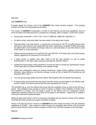
- 64. Basic Operation CAESAR II - User’s Guide The menus, toolbars, and accelerators offer a number of additional commands that the user can invoke to enter auxiliary processors or use special modelers or databases. These com- mands and general input instructions of the piping spreadsheet are discussed in detail in Chapter 5. To Enter the first element (element 10-20) of a simple model, do the following: 1. Enter the value 10-0 (10 ft) in the DX field. 2. Enter the value 8 (8-in. nominal) in the Diameter field. This is automatically con- verted to actual diameter. 3. Enter the letter “S” (standard schedule pipe wall) in the Wt/Sch field. This is automat- ically converted to wall thickness. 4. Enter 600 (degrees Fahrenheit) in the Temp 1 field. 5. Enter 150 (psig) in the Pressure 1 field. 6. Double-click on the Bend checkbox. This adds a long radius bend at the end of the element, and adds intermediate nodes 18 and 19 at the near weld and mid points of the bend respectively (node 20 physically represents the far weld point of the bend). 3-6 Quick Start and Basic Operation
- 65. CAESAR II - User’s Guide Basic Operation Bend Data 7. Double-click on the Restraint checkbox. This brings up a Restraint auxiliary screen. On the first Node field, enter 10; then select ANC from the first TYPE drop list. Quick Start and Basic Operation 3-7
- 66. Basic Operation CAESAR II - User’s Guide Restraint Settings 8. Select A106 B from the Material drop list. This selection fills in the material parame- ters such as density and modulus elasticity. 9. Double-click on the Allowable stress checkbox and select the B31.3 code from the Code drop list. Note Allowable stresses for the given material, temperature, and code are displayed automatically. 10. Enter 0.85SG (0.85 specific gravity) in the Fluid Density field. This value is automat- ically converted to density. 11. To enter the second element of the model 12. Press Alt-C, or the Continue toolbar, or use the Edit-Continue menu command to get a spreadsheet for a new element, element 20-30. 3-8 Quick Start and Basic Operation