SlideShare une entreprise Scribd logo
1  sur  21
What Is an Internetwork?
An internetwork is a collection of individual networks, connected by intermediate networking devices,
that functions as a single large network. Internetworking refers to the industry, products, and
procedures that meet the challenge of creating and administering internetworks.
Figure: Different Network Technologies Can Be Connected to Create an
Internetwork illustrates some different kinds of network technologies that can be interconnected by
routers and other networking devices to create an internetwork.
Figure: Different Network Technologies Can Be Connected to Create an Internetwork
History of Internetworking
The first networks were time-sharing networks that used mainframes and attached terminals. Such
environments were implemented by both IBM's Systems Network Architecture (SNA) and Digital's
network architecture.
Local-area networks (LANs) evolved around the PC revolution. LANs enabled multiple users in a
relatively small geographical area to exchange files and messages, as well as access shared
resources such as file servers and printers.
Wide-area networks (WANs) interconnect LANs with geographically dispersed users to create
connectivity. Some of the technologies used for connecting LANs include T1, T3, ATM, ISDN, ADSL,
Frame Relay, radio links, and others. New methods of connecting dispersed LANs are appearing
everyday.
Today, high-speed LANs and switched internetworks are becoming widely used, largely because they
operate at very high speeds and support such high-bandwidth applications as multimedia and
videoconferencing.
Internetworking evolved as a solution to three key problems: isolated LANs, duplication of resources,
and a lack of network management. Isolated LANs made electronic communication between different
offices or departments impossible. Duplication of resources meant that the same hardware and
software had to be supplied to each office or department, as did separate support staff. This lack of
network management meant that no centralized method of managing and troubleshooting networks
existed.
Internetworking Challenges
Implementing a functional internetwork is no simple task. Many challenges must be faced, especially
in the areas of connectivity, reliability, network management, and flexibility. Each area is key in
establishing an efficient and effective internetwork.
The challenge when connecting various systems is to support communication among disparate
technologies. Different sites, for example, may use different types of media operating at varying
speeds, or may even include different types of systems that need to communicate.
Because companies rely heavily on data communication, internetworks must provide a certain level of
reliability. This is an unpredictable world, so many large internetworks include redundancy to allow for
communication even when problems occur.
Furthermore, network management must provide centralized support and troubleshooting capabilities
in an internetwork. Configuration, security, performance, and other issues must be adequately
addressed for the internetwork to function smoothly. Security within an internetwork is essential. Many
people think of network security from the perspective of protecting the private network from outside
attacks. However, it is just as important to protect the network from internal attacks, especially
because most security breaches come from inside. Networks must also be secured so that the
internal network cannot be used as a tool to attack other external sites.
Early in the year 2000, many major web sites were the victims of distributed denial of service (DDOS)
attacks. These attacks were possible because a great number of private networks currently
connected with the Internet were not properly secured. These private networks were used as tools for
the attackers.
Because nothing in this world is stagnant, internetworks must be flexible enough to change with new
demands.
Open Systems Interconnection Reference Model
The Open Systems Interconnection (OSI) reference model describes how information from a software
application in one computer moves through a network medium to a software application in another
computer. The OSI reference model is a conceptual model composed of seven layers, each
specifying particular network functions. The model was developed by the International Organization
for Standardization (ISO) in 1984, and it is now considered the primary architectural model for
intercomputer communications. The OSI model divides the tasks involved with moving information
between networked computers into seven smaller, more manageable task groups. A task or group of
tasks is then assigned to each of the seven OSI layers. Each layer is reasonably self-contained so
that the tasks assigned to each layer can be implemented independently. This enables the solutions
offered by one layer to be updated without adversely affecting the other layers. The following list
details the seven layers of the Open Systems Interconnection (OSI) reference model:
 Layer 7-Application
 Layer 6-Presentation
 Layer 5-Session
 Layer 4-Transport
 Layer 3-Network
 Layer 2-Data link
 Layer 1-Physical
Note: A handy way to remember the seven layers is the sentence "All people seem to need data
processing." The beginning letter of each word corresponds to a layer.
 All-Application layer
 People-Presentation layer
 Seem-Session layer
 To-Transport layer
 Need-Network layer
 Data-Data link layer
 Processing-Physical layer
Figure: The OSI Reference Model Contains Seven Independent Layers illustrates the
seven-layer OSI reference model.
Figure: The OSI Reference Model Contains Seven Independent Layers
Characteristics of the OSI Layers
The seven layers of the OSI reference model can be divided into two categories: upper layers and
lower layers.
The upper layers of the OSI model deal with application issues and generally are implemented only in
software. The highest layer, the application layer, is closest to the end user. Both users and
application layer processes interact with software applications that contain a communications
component. The term upper layer is sometimes used to refer to any layer above another layer in the
OSI model.
The lower layers of the OSI model handle data transport issues. The physical layer and the data link
layer are implemented in hardware and software. The lowest layer, the physical layer, is closest to the
physical network medium (the network cabling, for example) and is responsible for actually placing
information on the medium.
Figure: Two Sets of Layers Make Up the OSI Layers illustrates the division between the
upper and lower OSI layers.
Figure: Two Sets of Layers Make Up the OSI Layers
Protocols
The OSI model provides a conceptual framework for communication between computers, but the
model itself is not a method of communication. Actual communication is made possible by using
communication protocols. In the context of data networking, a protocol is a formal set of rules and
conventions that governs how computers exchange information over a network medium. A protocol
implements the functions of one or more of the OSI layers.
A wide variety of communication protocols exist. Some of these protocols include LAN protocols,
WAN protocols, network protocols, and routing protocols. LAN protocols operate at the physical and
data link layers of the OSI model and define communication over the various LAN media. WAN
protocols operate at the lowest three layers of the OSI model and define communication over the
various wide-area media. Routing protocols are network layer protocols that are responsible for
exchanging information between routers so that the routers can select the proper path for network
traffic. Finally, network protocols are the various upper-layer protocols that exist in a given protocol
suite. Many protocols rely on others for operation. For example, many routing protocols use network
protocols to exchange information between routers. This concept of building upon the layers already
in existence is the foundation of the OSI model.
OSI Model and Communication Between Systems
Information being transferred from a software application in one computer system to a software
application in another must pass through the OSI layers. For example, if a software application in
System A has information to transmit to a software application in System B, the application program in
System A will pass its information to the application layer (Layer 7) of System A. The application layer
then passes the information to the presentation layer (Layer 6), which relays the data to the session
layer (Layer 5), and so on down to the physical layer (Layer 1). At the physical layer, the information
is placed on the physical network medium and is sent across the medium to System B. The physical
layer of System B removes the information from the physical medium, and then its physical layer
passes the information up to the data link layer (Layer 2), which passes it to the network layer (Layer
3), and so on, until it reaches the application layer (Layer 7) of System B. Finally, the application layer
of System B passes the information to the recipient application program to complete the
communication process.
Interaction Between OSI Model Layers
A given layer in the OSI model generally communicates with three other OSI layers: the layer directly
above it, the layer directly below it, and its peer layer in other networked computer systems. The data
link layer in System A, for example, communicates with the network layer of System A, the physical
layer of System A, and the data link layer in System B.
Figure: OSI Model Layers Communicate with Other Layers illustrates this example.
Figure: OSI Model Layers Communicate with Other Layers
OSI Layer Services
One OSI layer communicates with another layer to make use of the services provided by the second
layer. The services provided by adjacent layers help a given OSI layer communicate with its peer
layer in other computer systems. Three basic elements are involved in layer services: the service
user, the service provider, and the service access point (SAP).
In this context, the service user is the OSI layer that requests services from an adjacent OSI layer.
The service provider is the OSI layer that provides services to service users. OSI layers can provide
services to multiple service users. The SAP is a conceptual location at which one OSI layer can
request the services of another OSI layer.
Figure: Service Users, Providers, and SAPs Interact at the Network and Data Link
Layers illustrates how these three elements interact at the network and data link layers.
Figure: Service Users, Providers, and SAPs Interact at the Network and Data Link Layers
OSI Model Layers and Information Exchange
The seven OSI layers use various forms of control information to communicate with their peer layers
in other computer systems. This control information consists of specific requests and instructions that
are exchanged between peer OSI layers.
Control information typically takes one of two forms: headers and trailers. Headers are prepended to
data that has been passed down from upper layers. Trailers are appended to data that has been
passed down from upper layers. An OSI layer is not required to attach a header or a trailer to data
from upper layers.
Headers, trailers, and data are relative concepts, depending on the layer that analyzes the information
unit. At the network layer, for example, an information unit consists of a Layer 3 header and data. At
the data link layer, however, all the information passed down by the network layer (the Layer 3 header
and the data) is treated as data.
In other words, the data portion of an information unit at a given OSI layer potentially can contain
headers, trailers, and data from all the higher layers. This is known as encapsulation.
Figure: Headers and Data Can Be Encapsulated During Information Exchange shows
how the header and data from one layer are encapsulated into the header of the next lowest layer.
Figure: Headers and Data Can Be Encapsulated During Information Exchange
Information Exchange Process
The information exchange process occurs between peer OSI layers. Each layer in the source system
adds control information to data, and each layer in the destination system analyzes and removes the
control information from that data.
If System A has data from a software application to send to System B, the data is passed to the
application layer. The application layer in System A then communicates any control information
required by the application layer in System B by prepending a header to the data. The resulting
information unit (a header and the data) is passed to the presentation layer, which prepends its own
header containing control information intended for the presentation layer in System B. The information
unit grows in size as each layer prepends its own header (and, in some cases, a trailer) that contains
control information to be used by its peer layer in System B. At the physical layer, the entire
information unit is placed onto the network medium.
The physical layer in System B receives the information unit and passes it to the data link layer. The
data link layer in System B then reads the control information contained in the header prepended by
the data link layer in System A. The header is then removed, and the remainder of the information unit
is passed to the network layer. Each layer performs the same actions: The layer reads the header
from its peer layer, strips it off, and passes the remaining information unit to the next highest layer.
After the application layer performs these actions, the data is passed to the recipient software
application in System B, in exactly the form in which it was transmitted by the application in System A.
OSI Model Physical Layer
The physical layer defines the electrical, mechanical, procedural, and functional specifications for
activating, maintaining, and deactivating the physical link between communicating network systems.
Physical layer specifications define characteristics such as voltage levels, timing of voltage changes,
physical data rates, maximum transmission distances, and physical connectors. Physical layer
implementations can be categorized as either LAN or WAN specifications.
Figure: Physical Layer Implementations Can Be LAN or WAN Specifications illustrates
some common LAN and WAN physical layer implementations.
Figure: Physical Layer Implementations Can Be LAN or WAN Specifications
OSI Model Data Link Layer
The data link layer provides reliable transit of data across a physical network link. Different data link
layer specifications define different network and protocol characteristics, including physical
addressing, network topology, error notification, sequencing of frames, and flow control. Physical
addressing (as opposed to network addressing) defines how devices are addressed at the data link
layer. Network topology consists of the data link layer specifications that often define how devices are
to be physically connected, such as in a bus or a ring topology. Error notification alerts upper-layer
protocols that a transmission error has occurred, and the sequencing of data frames reorders frames
that are transmitted out of sequence. Finally, flow control moderates the transmission of data so that
the receiving device is not overwhelmed with more traffic than it can handle at one time.
The Institute of Electrical and Electronics Engineers (IEEE) has subdivided the data link layer into two
sublayers: Logical Link Control (LLC) and Media Access Control (MAC).
Figure: The Data Link Layer Contains Two Sublayers illustrates the IEEE sublayers of the
data link layer.
Figure: The Data Link Layer Contains Two Sublayers
The Logical Link Control (LLC) sublayer of the data link layer manages communications between
devices over a single link of a network. LLC is defined in the IEEE 802.2 specification and supports
both connectionless and connection-oriented services used by higher-layer protocols. IEEE 802.2
defines a number of fields in data link layer frames that enable multiple higher-layer protocols to share
a single physical data link. The Media Access Control (MAC) sublayer of the data link layer manages
protocol access to the physical network medium. The IEEE MAC specification defines MAC
addresses, which enable multiple devices to uniquely identify one another at the data link layer.
OSI Model Network Layer
The network layer defines the network address, which differs from the MAC address. Some network
layer implementations, such as the Internet Protocol (IP), define network addresses in a way that
route selection can be determined systematically by comparing the source network address with the
destination network address and applying the subnet mask. Because this layer defines the logical
network layout, routers can use this layer to determine how to forward packets. Because of this, much
of the design and configuration work for internetworks happens at Layer 3, the network layer.
OSI Model Transport Layer
The transport layer accepts data from the session layer and segments the data for transport across
the network. Generally, the transport layer is responsible for making sure that the data is delivered
error-free and in the proper sequence. Flow control generally occurs at the transport layer.
Flow control manages data transmission between devices so that the transmitting device does not
send more data than the receiving device can process. Multiplexing enables data from several
applications to be transmitted onto a single physical link. Virtual circuits are established, maintained,
and terminated by the transport layer. Error checking involves creating various mechanisms for
detecting transmission errors, while error recovery involves acting, such as requesting that data be
retransmitted, to resolve any errors that occur.
The transport protocols used on the Internet are TCP and UDP.
OSI Model Session Layer
The session layer establishes, manages, and terminates communication sessions. Communication
sessions consist of service requests and service responses that occur between applications located in
different network devices. These requests and responses are coordinated by protocols implemented
at the session layer. Some examples of session-layer implementations include Zone Information
Protocol (ZIP), the AppleTalk protocol that coordinates the name binding process; and Session
Control Protocol (SCP), the DECnet Phase IV session layer protocol.
OSI Model Presentation Layer
The presentation layer provides a variety of coding and conversion functions that are applied to
application layer data. These functions ensure that information sent from the application layer of one
system would be readable by the application layer of another system. Some examples of presentation
layer coding and conversion schemes include common data representation formats, conversion of
character representation formats, common data compression schemes, and common data encryption
schemes.
Common data representation formats, or the use of standard image, sound, and video formats,
enable the interchange of application data between different types of computer systems. Conversion
schemes are used to exchange information with systems by using different text and data
representations, such as EBCDIC and ASCII. Standard data compression schemes enable data that
is compressed at the source device to be properly decompressed at the destination. Standard data
encryption schemes enable data encrypted at the source device to be properly deciphered at the
destination.
Presentation layer implementations are not typically associated with a particular protocol stack. Some
well-known standards for video include QuickTime and Motion Picture Experts Group (MPEG).
QuickTime is an Apple Computer specification for video and audio, and MPEG is a standard for video
compression and coding.
Among the well-known graphic image formats are Graphics Interchange Format (GIF), Joint
Photographic Experts Group (JPEG), and Tagged Image File Format (TIFF). GIF is a standard for
compressing and coding graphic images. JPEG is another compression and coding standard for
graphic images, and TIFF is a standard coding format for graphic images.
OSI Model Application Layer
The application layer is the OSI layer closest to the end user, which means that both the OSI
application layer and the user interact directly with the software application.
This layer interacts with software applications that implement a communicating component. Such
application programs fall outside the scope of the OSI model. Application layer functions typically
include identifying communication partners, determining resource availability, and synchronizing
communication.
When identifying communication partners, the application layer determines the identity and availability
of communication partners for an application with data to transmit. When determining resource
availability, the application layer must decide whether sufficient network resources for the requested
communication exist. In synchronizing communication, all communication between applications
requires cooperation that is managed by the application layer.
Some examples of application layer implementations include Telnet, File Transfer Protocol (FTP), and
Simple Mail Transfer Protocol (SMTP).
Information Formats
The data and control information that is transmitted through internetworks takes a variety of forms.
The terms used to refer to these information formats are not used consistently in the internetworking
industry but sometimes are used interchangeably. Common information formats include frames,
packets, datagrams, segments, messages, cells, and data units.
A frame is an information unit whose source and destination are data link layer entities. A frame is
composed of the data link layer header (and possibly a trailer) and upper-layer data. The header and
trailer contain control information intended for the data link layer entity in the destination system. Data
from upper-layer entities is encapsulated in the data link layer header and trailer.
Figure: Data from Upper-Layer Entities Makes Up the Data Link Layer
Frame illustrates the basic components of a data link layer frame.
Figure: Data from Upper-Layer Entities Makes Up the Data Link Layer Frame
A packet is an information unit whose source and destination are network layer entities. A packet is
composed of the network layer header (and possibly a trailer) and upper-layer data. The header and
trailer contain control information intended for the network layer entity in the destination system. Data
from upper-layer entities is encapsulated in the network layer header and trailer.
Figure: Three Basic Components Make Up a Network Layer Packet illustrates the basic
components of a network layer packet.
Figure: Three Basic Components Make Up a Network Layer Packet
The term datagram usually refers to an information unit whose source and destination are network
layer entities that use connectionless network service.
The term segment usually refers to an information unit whose source and destination are transport
layer entities.
A message is an information unit whose source and destination entities exist above the network layer
(often at the application layer).
A cell is an information unit of a fixed size whose source and destination are data link layer entities.
Cells are used in switched environments, such as Asynchronous Transfer Mode (ATM) and Switched
Multimegabit Data Service (SMDS) networks. A cell is composed of the header and payload. The
header contains control information intended for the destination data link layer entity and is typically 5
bytes long. The payload contains upper-layer data that is encapsulated in the cell header and is
typically 48 bytes long.
The length of the header and the payload fields always are the same for each cell.
Figure: Two Components Make Up a Typical Cell depicts the components of a typical cell.
Figure: Two Components Make Up a Typical Cell
Data unit is a generic term that refers to a variety of information units. Some common data units are
service data units (SDUs), protocol data units, and bridge protocol data units (BPDUs). SDUs are
information units from upper-layer protocols that define a service request to a lower-layer protocol.
PDU is OSI terminology for a packet. BPDUs are used by the spanning-tree algorithm as hello
messages.
ISO Hierarchy of Networks
Large networks typically are organized as hierarchies. A hierarchical organization provides such
advantages as ease of management, flexibility, and a reduction in unnecessary traffic. Thus, the
International Organization for Standardization (ISO) has adopted a number of terminology
conventions for addressing network entities. Key terms defined in this section include end system
(ES), intermediate system (IS), area, and autonomous system (AS).
An ES is a network device that does not perform routing or other traffic forwarding functions. Typical
ESs include such devices as terminals, personal computers, and printers. An IS is a network device
that performs routing or other traffic-forwarding functions. Typical ISs include such devices as routers,
switches, and bridges. Two types of IS networks exist: intradomain IS and interdomain IS. An
intradomain IS communicates within a single autonomous system, while an interdomain IS
communicates within and between autonomous systems. An area is a logical group of network
segments and their attached devices. Areas are subdivisions of autonomous systems (AS's). An AS is
a collection of networks under a common administration that share a common routing strategy.
Autonomous systems are subdivided into areas, and an AS is sometimes called a domain.
Figure: A Hierarchical Network Contains Numerous Components illustrates a hierarchical
network and its components.
Figure: A Hierarchical Network Contains Numerous Components
Connection-Oriented and Connectionless Network Services
In general, transport protocols can be characterized as being either connection-oriented or
connectionless. Connection-oriented services must first establish a connection with the desired
service before passing any data. A connectionless service can send the data without any need to
establish a connection first. In general, connection-oriented services provide some level of delivery
guarantee, whereas connectionless services do not.
Connection-oriented service involves three phases: connection establishment, data transfer, and
connection termination.
During connection establishment, the end nodes may reserve resources for the connection. The end
nodes also may negotiate and establish certain criteria for the transfer, such as a window size used in
TCP connections. This resource reservation is one of the things exploited in some denial of service
(DOS) attacks. An attacking system will send many requests for establishing a connection but then
will never complete the connection. The attacked computer is then left with resources allocated for
many never-completed connections. Then, when an end node tries to complete an actual connection,
there are not enough resources for the valid connection.
The data transfer phase occurs when the actual data is transmitted over the connection. During data
transfer, most connection-oriented services will monitor for lost packets and handle resending them.
The protocol is generally also responsible for putting the packets in the right sequence before passing
the data up the protocol stack.
When the transfer of data is complete, the end nodes terminate the connection and release resources
reserved for the connection.
Connection-oriented network services have more overhead than connectionless ones. Connection-
oriented services must negotiate a connection, transfer data, and tear down the connection, whereas
a connectionless transfer can simply send the data without the added overhead of creating and
tearing down a connection. Each has its place in internetworks.
Internetwork Addressing
Internetwork addresses identify devices separately or as members of a group. Addressing schemes
vary depending on the protocol family and the OSI layer. Three types of internetwork addresses are
commonly used: data link layer addresses, Media Access Control (MAC) addresses, and network
layer addresses.
Data Link Layer Addresses
A data link layer address uniquely identifies each physical network connection of a network device.
Data-link addresses sometimes are referred to as physical or hardware addresses. Data-link
addresses usually exist within a flat address space and have a pre-established and typically fixed
relationship to a specific device.
End systems generally have only one physical network connection and thus have only one data-link
address. Routers and other internetworking devices typically have multiple physical network
connections and therefore have multiple data-link addresses.
Figure: Each Interface on a Device Is Uniquely Identified by a Data-Link
Address illustrates how each interface on a device is uniquely identified by a data-link address.
Figure: Each Interface on a Device Is Uniquely Identified by a Data-Link Address
MAC Addresses
Media Access Control (MAC) addresses consist of a subset of data link layer addresses. MAC
addresses identify network entities in LANs that implement the IEEE MAC addresses of the data link
layer. As with most data-link addresses, MAC addresses are unique for each LAN interface.
Figure: MAC Addresses, Data-Link Addresses, and the IEEE Sublayers of the Data
Link Layer Are All Related illustrates the relationship between MAC addresses, data-link
addresses, and the IEEE sublayers of the data link layer.
Figure: MAC Addresses, Data-Link Addresses, and the IEEE Sublayers of the Data Link Layer
Are All Related
MAC addresses are 48 bits in length and are expressed as 12 hexadecimal digits. The first 6
hexadecimal digits, which are administered by the IEEE, identify the manufacturer or vendor and thus
comprise the Organizationally Unique Identifier (OUI). The last 6 hexadecimal digits comprise the
interface serial number, or another value administered by the specific vendor. MAC addresses
sometimes are called burned-in addresses (BIAs) because they are burned into read-only memory
(ROM) and are copied into random-access memory (RAM) when the interface card initializes.
Figure: The MAC Address Contains a Unique Format of Hexadecimal Digits illustrates
the MAC address format.
Figure: The MAC Address Contains a Unique Format of Hexadecimal Digits
Mapping Addresses
Because internetworks generally use network addresses to route traffic around the network, there is a
need to map network addresses to MAC addresses. When the network layer has determined the
destination station's network address, it must forward the information over a physical network using a
MAC address. Different protocol suites use different methods to perform this mapping, but the most
popular is Address Resolution Protocol (ARP).
Different protocol suites use different methods for determining the MAC address of a device. The
following three methods are used most often. Address Resolution Protocol (ARP) maps network
addresses to MAC addresses. The Hello protocol enables network devices to learn the MAC
addresses of other network devices. MAC addresses either are embedded in the network layer
address or are generated by an algorithm.
Address Resolution Protocol (ARP) is the method used in the TCP/IP suite. When a network device
needs to send data to another device on the same network, it knows the source and destination
network addresses for the data transfer. It must somehow map the destination address to a MAC
address before forwarding the data. First, the sending station will check its ARP table to see if it has
already discovered this destination station's MAC address. If it has not, it will send a broadcast on the
network with the destination station's IP address contained in the broadcast. Every station on the
network receives the broadcast and compares the embedded IP address to its own. Only the station
with the matching IP address replies to the sending station with a packet containing the MAC address
for the station. The first station then adds this information to its ARP table for future reference and
proceeds to transfer the data.
When the destination device lies on a remote network, one beyond a router, the process is the same
except that the sending station sends the ARP request for the MAC address of its default gateway. It
then forwards the information to that device. The default gateway will then forward the information
over whatever networks necessary to deliver the packet to the network on which the destination
device resides. The router on the destination device's network then uses ARP to obtain the MAC of
the actual destination device and delivers the packet.
The Hello protocol is a network layer protocol that enables network devices to identify one another
and indicate that they are still functional. When a new end system powers up, for example, it
broadcasts hello messages onto the network. Devices on the network then return hello replies, and
hello messages are also sent at specific intervals to indicate that they are still functional. Network
devices can learn the MAC addresses of other devices by examining Hello protocol packets.
Three protocols use predictable MAC addresses. In these protocol suites, MAC addresses are
predictable because the network layer either embeds the MAC address in the network layer address
or uses an algorithm to determine the MAC address. The three protocols are Xerox Network Systems
(XNS), Novell Internetwork Packet Exchange (IPX), and DECnet Phase IV.
Network Layer Addresses
A network layer address identifies an entity at the network layer of the OSI layers. Network addresses
usually exist within a hierarchical address space and sometimes are called virtual or logical
addresses.
The relationship between a network address and a device is logical and unfixed; it typically is based
either on physical network characteristics (the device is on a particular network segment) or on
groupings that have no physical basis (the device is part of an AppleTalk zone). End systems require
one network layer address for each network layer protocol that they support. (This assumes that the
device has only one physical network connection.) Routers and other internetworking devices require
one network layer address per physical network connection for each network layer protocol
supported. For example, a router with three interfaces each running AppleTalk, TCP/IP, and OSI must
have three network layer addresses for each interface. The router therefore has nine network layer
addresses.
Figure: Each Network Interface Must Be Assigned a Network Address for Each
Protocol Supported illustrates how each network interface must be assigned a network address
for each protocol supported.
Figure: Each Network Interface Must Be Assigned a Network Address for Each Protocol
Supported
Hierarchical Versus Flat Address Space
Internetwork address space typically takes one of two forms: hierarchical address space or flat
address space. A hierarchical address space is organized into numerous subgroups, each
successively narrowing an address until it points to a single device (in a manner similar to street
addresses). A flat address space is organized into a single group (in a manner similar to U.S. Social
Security numbers).
Hierarchical addressing offers certain advantages over flat-addressing schemes. Address sorting and
recall is simplified using comparison operations. For example, "Ireland" in a street address eliminates
any other country as a possible location.
Figure: Hierarchical and Flat Address Spaces Differ in Comparison
Operations illustrates the difference between hierarchical and flat address spaces.
Figure: Hierarchical and Flat Address Spaces Differ in Comparison Operations
Address Assignments
Addresses are assigned to devices as one of two types: static and dynamic. Static addresses are
assigned by a network administrator according to a preconceived internetwork addressing plan. A
static address does not change until the network administrator manually changes it. Dynamic
addresses are obtained by devices when they attach to a network, by means of some protocol-
specific process. A device using a dynamic address often has a different address each time that it
connects to the network. Some networks use a server to assign addresses. Server-assigned
addresses are recycled for reuse as devices disconnect. A device is therefore likely to have a different
address each time that it connects to the network.
Addresses Versus Names
Internetwork devices usually have both a name and an address associated with them. Internetwork
names typically are location-independent and remain associated with a device wherever that device
moves (for example, from one building to another). Internetwork addresses usually are location-
dependent and change when a device is moved (although MAC addresses are an exception to this
rule). As with network addresses being mapped to MAC addresses, names are usually mapped to
network addresses through some protocol. The Internet uses Domain Name System (DNS) to map
the name of a device to its IP address. For example, it's easier for you to remember www.cisco.com
instead of some IP address. Therefore, you type www.cisco.com into your browser when you want to
access Cisco's web site. Your computer performs a DNS lookup of the IP address for Cisco's web
server and then communicates with it using the network address.
Flow Control Basics
Flow control is a function that prevents network congestion by ensuring that transmitting devices do
not overwhelm receiving devices with data. A high-speed computer, for example, may generate traffic
faster than the network can transfer it, or faster than the destination device can receive and process it.
The three commonly used methods for handling network congestion are buffering, transmitting
source-quench messages, and windowing.
Buffering is used by network devices to temporarily store bursts of excess data in memory until they
can be processed. Occasional data bursts are easily handled by buffering. Excess data bursts can
exhaust memory, however, forcing the device to discard any additional datagrams that arrive.
Source-quench messages are used by receiving devices to help prevent their buffers from
overflowing. The receiving device sends source-quench messages to request that the source reduce
its current rate of data transmission. First, the receiving device begins discarding received data due to
overflowing buffers. Second, the receiving device begins sending source-quench messages to the
transmitting device at the rate of one message for each packet dropped. The source device receives
the source-quench messages and lowers the data rate until it stops receiving the messages. Finally,
the source device then gradually increases the data rate as long as no further source-quench
requests are received.
Windowing is a flow-control scheme in which the source device requires an acknowledgment from the
destination after a certain number of packets have been transmitted. With a window size of 3, the
source requires an acknowledgment after sending three packets, as follows. First, the source device
sends three packets to the destination device. Then, after receiving the three packets, the destination
device sends an acknowledgment to the source. The source receives the acknowledgment and sends
three more packets. If the destination does not receive one or more of the packets for some reason,
such as overflowing buffers, it does not receive enough packets to send an acknowledgment. The
source then retransmits the packets at a reduced transmission rate.
Error-Checking Basics
Error-checking schemes determine whether transmitted data has become corrupt or otherwise
damaged while traveling from the source to the destination. Error checking is implemented at several
of the OSI layers.
One common error-checking scheme is the cyclic redundancy check (CRC), which detects and
discards corrupted data. Error-correction functions (such as data retransmission) are left to higher-
layer protocols. A CRC value is generated by a calculation that is performed at the source device. The
destination device compares this value to its own calculation to determine whether errors occurred
during transmission. First, the source device performs a predetermined set of calculations over the
contents of the packet to be sent. Then, the source places the calculated value in the packet and
sends the packet to the destination. The destination performs the same predetermined set of
calculations over the contents of the packet and then compares its computed value with that
contained in the packet. If the values are equal, the packet is considered valid. If the values are
unequal, the packet contains errors and is discarded.
Multiplexing Basics
Multiplexing is a process in which multiple data channels are combined into a single data or physical
channel at the source. Multiplexing can be implemented at any of the OSI layers. Conversely,
demultiplexing is the process of separating multiplexed data channels at the destination. One
example of multiplexing is when data from multiple applications is multiplexed into a single lower-layer
data packet.
Figure: Multiple Applications Can Be Multiplexed into a Single Lower-Layer Data
Packet illustrates this example.
Figure: Multiple Applications Can Be Multiplexed into a Single Lower-Layer Data Packet
Another example of multiplexing is when data from multiple devices is combined into a single physical
channel (using a device called a multiplexer).
Figure: Multiple Devices Can Be Multiplexed into a Single Physical Channel illustrates
this example.
Figure: Multiple Devices Can Be Multiplexed into a Single Physical Channel
A multiplexer is a physical layer device that combines multiple data streams into one or more output
channels at the source. Multiplexers demultiplex the channels into multiple data streams at the remote
end and thus maximize the use of the bandwidth of the physical medium by enabling it to be shared
by multiple traffic sources.
Some methods used for multiplexing data are time-division multiplexing (TDM), asynchronous time-
division multiplexing (ATDM), frequency-division multiplexing (FDM), and statistical multiplexing.
In TDM, information from each data channel is allocated bandwidth based on preassigned time slots,
regardless of whether there is data to transmit. In ATDM, information from data channels is allocated
bandwidth as needed by using dynamically assigned time slots. In FDM, information from each data
channel is allocated bandwidth based on the signal frequency of the traffic. In statistical multiplexing,
bandwidth is dynamically allocated to any data channels that have information to transmit.
Standards Organizations
A wide variety of organizations contribute to internetworking standards by providing forums for
discussion, turning informal discussion into formal specifications, and proliferating specifications after
they are standardized.
Most standards organizations create formal standards by using specific processes: organizing ideas,
discussing the approach, developing draft standards, voting on all or certain aspects of the standards,
and then formally releasing the completed standard to the public.
Some of the best-known standards organizations that contribute to internetworking standards include
these:
 International Organization for Standardization (ISO)-ISO is an international standards
organization responsible for a wide range of standards, including many that are relevant to
networking. Its best-known contribution is the development of the OSI reference model and the
OSI protocol suite.
 American National Standards Institute (ANSI)-ANSI, which is also a member of the ISO, is the
coordinating body for voluntary standards groups within the United States. ANSI developed the
Fiber Distributed Data Interface (FDDI) and other communications standards.
 Electronic Industries Association (EIA)-EIA specifies electrical transmission standards,
including those used in networking. The EIA developed the widely used EIA/TIA-232 standard
(formerly known as RS-232).
 Institute of Electrical and Electronic Engineers (IEEE)-IEEE is a professional organization that
defines networking and other standards. The IEEE developed the widely used LAN standards
IEEE 802.3 and IEEE 802.5.
 International Telecommunication Union Telecommunication Standardization Sector (ITU-
T)-Formerly called the Committee for International Telegraph and Telephone (CCITT), ITU-T is
now an international organization that develops communication standards. The ITU-T developed
X.25 and other communications standards.
 Internet Activities Board (IAB)-IAB is a group of internetwork researchers who discuss issues
pertinent to the Internet and set Internet policies through decisions and task forces. The IAB
designates some Request For Comments (RFC) documents as Internet standards, including
Transmission Control Protocol/Internet Protocol (TCP/IP) and the Simple Network Management
Protocol (SNMP).
Summary
This article introduced the building blocks on which internetworks are built. Under-standing where
complex pieces of internetworks fit into the OSI model will help you understand the concepts better.
Internetworks are complex systems that, when viewed as a whole, are too much to understand. Only
by breaking the network down into the conceptual pieces can it be easily understood. As you read
and experience internetworks, try to think of them in terms of OSI layers and conceptual pieces.
Understanding the interaction between various layers and protocols makes designing, configuring,
and diagnosing internetworks possible. Without understanding of the building blocks, you cannot
understand the interaction between them.
Review Questions
Q - What are the layers of the OSI model?
A - Application, presentation, session, transport, network, data link, physical. Remember the sentence
"All people seem to need data processing."
Q - Which layer determines path selection in an internetwork?
A - Layer 3, the network layer.
Q - What types of things are defined at the physical layer?
A - Voltage levels, time of voltage changes, physical data rates, maximum transmission distances,
physical connectors, and type of media.
Q - What is one method of mapping network addresses to MAC addresses?
A - ARP, Hello, predictable.
Q - Which includes more overhead, connection-oriented or connectionless services?
A - Connection-oriented.

Contenu connexe

Tendances

Tendances (20)

Networking Models
Networking ModelsNetworking Models
Networking Models
 
Hy3313681373
Hy3313681373Hy3313681373
Hy3313681373
 
Introduction to OSI MODEL
Introduction to OSI MODEL Introduction to OSI MODEL
Introduction to OSI MODEL
 
Presentation on osi layer
Presentation on osi layerPresentation on osi layer
Presentation on osi layer
 
Modern computer network technologies
Modern computer network technologies Modern computer network technologies
Modern computer network technologies
 
THE OSI MODEL
THE OSI MODELTHE OSI MODEL
THE OSI MODEL
 
Sept 2017 network standards and models
Sept 2017   network standards and modelsSept 2017   network standards and models
Sept 2017 network standards and models
 
Osi model (open systems interconnection)
Osi model (open systems interconnection)Osi model (open systems interconnection)
Osi model (open systems interconnection)
 
PACE-IT: The OSI Networking Reference Model
PACE-IT: The OSI Networking Reference ModelPACE-IT: The OSI Networking Reference Model
PACE-IT: The OSI Networking Reference Model
 
Lesson 7
Lesson 7Lesson 7
Lesson 7
 
Modelo osi
Modelo osiModelo osi
Modelo osi
 
2nd class
2nd class2nd class
2nd class
 
Osi model
Osi modelOsi model
Osi model
 
The osi layers and ethernet protocols
The osi layers and ethernet protocolsThe osi layers and ethernet protocols
The osi layers and ethernet protocols
 
Uses of computer networks
Uses of computer networksUses of computer networks
Uses of computer networks
 
Computer Network [OSI Model]
Computer Network [OSI Model]Computer Network [OSI Model]
Computer Network [OSI Model]
 
Computer networks
Computer networksComputer networks
Computer networks
 
Osi model
Osi model Osi model
Osi model
 
Introduction To Computer Networks
Introduction To Computer Networks Introduction To Computer Networks
Introduction To Computer Networks
 
OSI Model
OSI ModelOSI Model
OSI Model
 

En vedette

Alejandra serna colanta (1)
Alejandra serna colanta (1)Alejandra serna colanta (1)
Alejandra serna colanta (1)3218267155
 
Android development-workshop-v2-1228043706544191-8
Android development-workshop-v2-1228043706544191-8Android development-workshop-v2-1228043706544191-8
Android development-workshop-v2-1228043706544191-8maxminhaj1
 
Industrial engineering
Industrial engineeringIndustrial engineering
Industrial engineeringElimarVanessa
 
Learder ability
Learder abilityLearder ability
Learder abilityshuyanmiao
 
Únete al equipo de voluntari@s
Únete al equipo de voluntari@sÚnete al equipo de voluntari@s
Únete al equipo de voluntari@sEdgar Martinez
 

En vedette (8)

Module 2
Module 2Module 2
Module 2
 
Alejandra serna colanta (1)
Alejandra serna colanta (1)Alejandra serna colanta (1)
Alejandra serna colanta (1)
 
Android development-workshop-v2-1228043706544191-8
Android development-workshop-v2-1228043706544191-8Android development-workshop-v2-1228043706544191-8
Android development-workshop-v2-1228043706544191-8
 
Presentation 3
Presentation 3Presentation 3
Presentation 3
 
What is cloud
What is cloudWhat is cloud
What is cloud
 
Industrial engineering
Industrial engineeringIndustrial engineering
Industrial engineering
 
Learder ability
Learder abilityLearder ability
Learder ability
 
Únete al equipo de voluntari@s
Únete al equipo de voluntari@sÚnete al equipo de voluntari@s
Únete al equipo de voluntari@s
 

Similaire à What is an Internetwork? Understanding Connected Networks in 40 Characters

Similaire à What is an Internetwork? Understanding Connected Networks in 40 Characters (20)

Ccna complete notes
Ccna complete notesCcna complete notes
Ccna complete notes
 
Internetworking basics
Internetworking basicsInternetworking basics
Internetworking basics
 
Networking Standards And Protocols
Networking Standards And ProtocolsNetworking Standards And Protocols
Networking Standards And Protocols
 
7 Layers Of The OSI Model
7 Layers Of The OSI Model7 Layers Of The OSI Model
7 Layers Of The OSI Model
 
Osi model 1
Osi model 1Osi model 1
Osi model 1
 
Lecture2
Lecture2Lecture2
Lecture2
 
Osi model
Osi modelOsi model
Osi model
 
Lecture2
Lecture2Lecture2
Lecture2
 
Osi model
Osi modelOsi model
Osi model
 
Osi model
Osi modelOsi model
Osi model
 
OSI MODEL
    OSI MODEL    OSI MODEL
OSI MODEL
 
Lecture2
Lecture2Lecture2
Lecture2
 
Lecture2
Lecture2Lecture2
Lecture2
 
Osi Layer model provided by TopTechy.com
Osi Layer model provided by TopTechy.comOsi Layer model provided by TopTechy.com
Osi Layer model provided by TopTechy.com
 
Internet
InternetInternet
Internet
 
OSI models
OSI modelsOSI models
OSI models
 
OSI MODEL
OSI MODELOSI MODEL
OSI MODEL
 
Practical Wireless, Ethernet and TCP/IP Networking
Practical Wireless, Ethernet and TCP/IP NetworkingPractical Wireless, Ethernet and TCP/IP Networking
Practical Wireless, Ethernet and TCP/IP Networking
 
THE OSI MODEL
THE OSI MODEL THE OSI MODEL
THE OSI MODEL
 
Internetworking
InternetworkingInternetworking
Internetworking
 

Dernier

The Codex of Business Writing Software for Real-World Solutions 2.pptx
The Codex of Business Writing Software for Real-World Solutions 2.pptxThe Codex of Business Writing Software for Real-World Solutions 2.pptx
The Codex of Business Writing Software for Real-World Solutions 2.pptxMalak Abu Hammad
 
Raspberry Pi 5: Challenges and Solutions in Bringing up an OpenGL/Vulkan Driv...
Raspberry Pi 5: Challenges and Solutions in Bringing up an OpenGL/Vulkan Driv...Raspberry Pi 5: Challenges and Solutions in Bringing up an OpenGL/Vulkan Driv...
Raspberry Pi 5: Challenges and Solutions in Bringing up an OpenGL/Vulkan Driv...Igalia
 
08448380779 Call Girls In Civil Lines Women Seeking Men
08448380779 Call Girls In Civil Lines Women Seeking Men08448380779 Call Girls In Civil Lines Women Seeking Men
08448380779 Call Girls In Civil Lines Women Seeking MenDelhi Call girls
 
Salesforce Community Group Quito, Salesforce 101
Salesforce Community Group Quito, Salesforce 101Salesforce Community Group Quito, Salesforce 101
Salesforce Community Group Quito, Salesforce 101Paola De la Torre
 
04-2024-HHUG-Sales-and-Marketing-Alignment.pptx
04-2024-HHUG-Sales-and-Marketing-Alignment.pptx04-2024-HHUG-Sales-and-Marketing-Alignment.pptx
04-2024-HHUG-Sales-and-Marketing-Alignment.pptxHampshireHUG
 
WhatsApp 9892124323 ✓Call Girls In Kalyan ( Mumbai ) secure service
WhatsApp 9892124323 ✓Call Girls In Kalyan ( Mumbai ) secure serviceWhatsApp 9892124323 ✓Call Girls In Kalyan ( Mumbai ) secure service
WhatsApp 9892124323 ✓Call Girls In Kalyan ( Mumbai ) secure servicePooja Nehwal
 
How to Troubleshoot Apps for the Modern Connected Worker
How to Troubleshoot Apps for the Modern Connected WorkerHow to Troubleshoot Apps for the Modern Connected Worker
How to Troubleshoot Apps for the Modern Connected WorkerThousandEyes
 
Swan(sea) Song – personal research during my six years at Swansea ... and bey...
Swan(sea) Song – personal research during my six years at Swansea ... and bey...Swan(sea) Song – personal research during my six years at Swansea ... and bey...
Swan(sea) Song – personal research during my six years at Swansea ... and bey...Alan Dix
 
Understanding the Laravel MVC Architecture
Understanding the Laravel MVC ArchitectureUnderstanding the Laravel MVC Architecture
Understanding the Laravel MVC ArchitecturePixlogix Infotech
 
A Domino Admins Adventures (Engage 2024)
A Domino Admins Adventures (Engage 2024)A Domino Admins Adventures (Engage 2024)
A Domino Admins Adventures (Engage 2024)Gabriella Davis
 
How to convert PDF to text with Nanonets
How to convert PDF to text with NanonetsHow to convert PDF to text with Nanonets
How to convert PDF to text with Nanonetsnaman860154
 
Maximizing Board Effectiveness 2024 Webinar.pptx
Maximizing Board Effectiveness 2024 Webinar.pptxMaximizing Board Effectiveness 2024 Webinar.pptx
Maximizing Board Effectiveness 2024 Webinar.pptxOnBoard
 
My Hashitalk Indonesia April 2024 Presentation
My Hashitalk Indonesia April 2024 PresentationMy Hashitalk Indonesia April 2024 Presentation
My Hashitalk Indonesia April 2024 PresentationRidwan Fadjar
 
Enhancing Worker Digital Experience: A Hands-on Workshop for Partners
Enhancing Worker Digital Experience: A Hands-on Workshop for PartnersEnhancing Worker Digital Experience: A Hands-on Workshop for Partners
Enhancing Worker Digital Experience: A Hands-on Workshop for PartnersThousandEyes
 
IAC 2024 - IA Fast Track to Search Focused AI Solutions
IAC 2024 - IA Fast Track to Search Focused AI SolutionsIAC 2024 - IA Fast Track to Search Focused AI Solutions
IAC 2024 - IA Fast Track to Search Focused AI SolutionsEnterprise Knowledge
 
Tech-Forward - Achieving Business Readiness For Copilot in Microsoft 365
Tech-Forward - Achieving Business Readiness For Copilot in Microsoft 365Tech-Forward - Achieving Business Readiness For Copilot in Microsoft 365
Tech-Forward - Achieving Business Readiness For Copilot in Microsoft 3652toLead Limited
 
Breaking the Kubernetes Kill Chain: Host Path Mount
Breaking the Kubernetes Kill Chain: Host Path MountBreaking the Kubernetes Kill Chain: Host Path Mount
Breaking the Kubernetes Kill Chain: Host Path MountPuma Security, LLC
 
SQL Database Design For Developers at php[tek] 2024
SQL Database Design For Developers at php[tek] 2024SQL Database Design For Developers at php[tek] 2024
SQL Database Design For Developers at php[tek] 2024Scott Keck-Warren
 
Scaling API-first – The story of a global engineering organization
Scaling API-first – The story of a global engineering organizationScaling API-first – The story of a global engineering organization
Scaling API-first – The story of a global engineering organizationRadu Cotescu
 
Google AI Hackathon: LLM based Evaluator for RAG
Google AI Hackathon: LLM based Evaluator for RAGGoogle AI Hackathon: LLM based Evaluator for RAG
Google AI Hackathon: LLM based Evaluator for RAGSujit Pal
 

Dernier (20)

The Codex of Business Writing Software for Real-World Solutions 2.pptx
The Codex of Business Writing Software for Real-World Solutions 2.pptxThe Codex of Business Writing Software for Real-World Solutions 2.pptx
The Codex of Business Writing Software for Real-World Solutions 2.pptx
 
Raspberry Pi 5: Challenges and Solutions in Bringing up an OpenGL/Vulkan Driv...
Raspberry Pi 5: Challenges and Solutions in Bringing up an OpenGL/Vulkan Driv...Raspberry Pi 5: Challenges and Solutions in Bringing up an OpenGL/Vulkan Driv...
Raspberry Pi 5: Challenges and Solutions in Bringing up an OpenGL/Vulkan Driv...
 
08448380779 Call Girls In Civil Lines Women Seeking Men
08448380779 Call Girls In Civil Lines Women Seeking Men08448380779 Call Girls In Civil Lines Women Seeking Men
08448380779 Call Girls In Civil Lines Women Seeking Men
 
Salesforce Community Group Quito, Salesforce 101
Salesforce Community Group Quito, Salesforce 101Salesforce Community Group Quito, Salesforce 101
Salesforce Community Group Quito, Salesforce 101
 
04-2024-HHUG-Sales-and-Marketing-Alignment.pptx
04-2024-HHUG-Sales-and-Marketing-Alignment.pptx04-2024-HHUG-Sales-and-Marketing-Alignment.pptx
04-2024-HHUG-Sales-and-Marketing-Alignment.pptx
 
WhatsApp 9892124323 ✓Call Girls In Kalyan ( Mumbai ) secure service
WhatsApp 9892124323 ✓Call Girls In Kalyan ( Mumbai ) secure serviceWhatsApp 9892124323 ✓Call Girls In Kalyan ( Mumbai ) secure service
WhatsApp 9892124323 ✓Call Girls In Kalyan ( Mumbai ) secure service
 
How to Troubleshoot Apps for the Modern Connected Worker
How to Troubleshoot Apps for the Modern Connected WorkerHow to Troubleshoot Apps for the Modern Connected Worker
How to Troubleshoot Apps for the Modern Connected Worker
 
Swan(sea) Song – personal research during my six years at Swansea ... and bey...
Swan(sea) Song – personal research during my six years at Swansea ... and bey...Swan(sea) Song – personal research during my six years at Swansea ... and bey...
Swan(sea) Song – personal research during my six years at Swansea ... and bey...
 
Understanding the Laravel MVC Architecture
Understanding the Laravel MVC ArchitectureUnderstanding the Laravel MVC Architecture
Understanding the Laravel MVC Architecture
 
A Domino Admins Adventures (Engage 2024)
A Domino Admins Adventures (Engage 2024)A Domino Admins Adventures (Engage 2024)
A Domino Admins Adventures (Engage 2024)
 
How to convert PDF to text with Nanonets
How to convert PDF to text with NanonetsHow to convert PDF to text with Nanonets
How to convert PDF to text with Nanonets
 
Maximizing Board Effectiveness 2024 Webinar.pptx
Maximizing Board Effectiveness 2024 Webinar.pptxMaximizing Board Effectiveness 2024 Webinar.pptx
Maximizing Board Effectiveness 2024 Webinar.pptx
 
My Hashitalk Indonesia April 2024 Presentation
My Hashitalk Indonesia April 2024 PresentationMy Hashitalk Indonesia April 2024 Presentation
My Hashitalk Indonesia April 2024 Presentation
 
Enhancing Worker Digital Experience: A Hands-on Workshop for Partners
Enhancing Worker Digital Experience: A Hands-on Workshop for PartnersEnhancing Worker Digital Experience: A Hands-on Workshop for Partners
Enhancing Worker Digital Experience: A Hands-on Workshop for Partners
 
IAC 2024 - IA Fast Track to Search Focused AI Solutions
IAC 2024 - IA Fast Track to Search Focused AI SolutionsIAC 2024 - IA Fast Track to Search Focused AI Solutions
IAC 2024 - IA Fast Track to Search Focused AI Solutions
 
Tech-Forward - Achieving Business Readiness For Copilot in Microsoft 365
Tech-Forward - Achieving Business Readiness For Copilot in Microsoft 365Tech-Forward - Achieving Business Readiness For Copilot in Microsoft 365
Tech-Forward - Achieving Business Readiness For Copilot in Microsoft 365
 
Breaking the Kubernetes Kill Chain: Host Path Mount
Breaking the Kubernetes Kill Chain: Host Path MountBreaking the Kubernetes Kill Chain: Host Path Mount
Breaking the Kubernetes Kill Chain: Host Path Mount
 
SQL Database Design For Developers at php[tek] 2024
SQL Database Design For Developers at php[tek] 2024SQL Database Design For Developers at php[tek] 2024
SQL Database Design For Developers at php[tek] 2024
 
Scaling API-first – The story of a global engineering organization
Scaling API-first – The story of a global engineering organizationScaling API-first – The story of a global engineering organization
Scaling API-first – The story of a global engineering organization
 
Google AI Hackathon: LLM based Evaluator for RAG
Google AI Hackathon: LLM based Evaluator for RAGGoogle AI Hackathon: LLM based Evaluator for RAG
Google AI Hackathon: LLM based Evaluator for RAG
 

What is an Internetwork? Understanding Connected Networks in 40 Characters

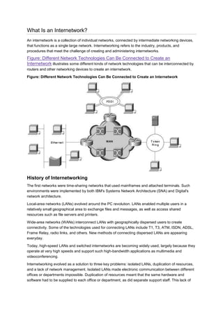
  • 1. What Is an Internetwork? An internetwork is a collection of individual networks, connected by intermediate networking devices, that functions as a single large network. Internetworking refers to the industry, products, and procedures that meet the challenge of creating and administering internetworks. Figure: Different Network Technologies Can Be Connected to Create an Internetwork illustrates some different kinds of network technologies that can be interconnected by routers and other networking devices to create an internetwork. Figure: Different Network Technologies Can Be Connected to Create an Internetwork History of Internetworking The first networks were time-sharing networks that used mainframes and attached terminals. Such environments were implemented by both IBM's Systems Network Architecture (SNA) and Digital's network architecture. Local-area networks (LANs) evolved around the PC revolution. LANs enabled multiple users in a relatively small geographical area to exchange files and messages, as well as access shared resources such as file servers and printers. Wide-area networks (WANs) interconnect LANs with geographically dispersed users to create connectivity. Some of the technologies used for connecting LANs include T1, T3, ATM, ISDN, ADSL, Frame Relay, radio links, and others. New methods of connecting dispersed LANs are appearing everyday. Today, high-speed LANs and switched internetworks are becoming widely used, largely because they operate at very high speeds and support such high-bandwidth applications as multimedia and videoconferencing. Internetworking evolved as a solution to three key problems: isolated LANs, duplication of resources, and a lack of network management. Isolated LANs made electronic communication between different offices or departments impossible. Duplication of resources meant that the same hardware and software had to be supplied to each office or department, as did separate support staff. This lack of
  • 2. network management meant that no centralized method of managing and troubleshooting networks existed. Internetworking Challenges Implementing a functional internetwork is no simple task. Many challenges must be faced, especially in the areas of connectivity, reliability, network management, and flexibility. Each area is key in establishing an efficient and effective internetwork. The challenge when connecting various systems is to support communication among disparate technologies. Different sites, for example, may use different types of media operating at varying speeds, or may even include different types of systems that need to communicate. Because companies rely heavily on data communication, internetworks must provide a certain level of reliability. This is an unpredictable world, so many large internetworks include redundancy to allow for communication even when problems occur. Furthermore, network management must provide centralized support and troubleshooting capabilities in an internetwork. Configuration, security, performance, and other issues must be adequately addressed for the internetwork to function smoothly. Security within an internetwork is essential. Many people think of network security from the perspective of protecting the private network from outside attacks. However, it is just as important to protect the network from internal attacks, especially because most security breaches come from inside. Networks must also be secured so that the internal network cannot be used as a tool to attack other external sites. Early in the year 2000, many major web sites were the victims of distributed denial of service (DDOS) attacks. These attacks were possible because a great number of private networks currently connected with the Internet were not properly secured. These private networks were used as tools for the attackers. Because nothing in this world is stagnant, internetworks must be flexible enough to change with new demands. Open Systems Interconnection Reference Model The Open Systems Interconnection (OSI) reference model describes how information from a software application in one computer moves through a network medium to a software application in another computer. The OSI reference model is a conceptual model composed of seven layers, each specifying particular network functions. The model was developed by the International Organization for Standardization (ISO) in 1984, and it is now considered the primary architectural model for intercomputer communications. The OSI model divides the tasks involved with moving information between networked computers into seven smaller, more manageable task groups. A task or group of tasks is then assigned to each of the seven OSI layers. Each layer is reasonably self-contained so that the tasks assigned to each layer can be implemented independently. This enables the solutions offered by one layer to be updated without adversely affecting the other layers. The following list details the seven layers of the Open Systems Interconnection (OSI) reference model:  Layer 7-Application  Layer 6-Presentation  Layer 5-Session  Layer 4-Transport  Layer 3-Network  Layer 2-Data link
  • 3.  Layer 1-Physical Note: A handy way to remember the seven layers is the sentence "All people seem to need data processing." The beginning letter of each word corresponds to a layer.  All-Application layer  People-Presentation layer  Seem-Session layer  To-Transport layer  Need-Network layer  Data-Data link layer  Processing-Physical layer Figure: The OSI Reference Model Contains Seven Independent Layers illustrates the seven-layer OSI reference model. Figure: The OSI Reference Model Contains Seven Independent Layers Characteristics of the OSI Layers The seven layers of the OSI reference model can be divided into two categories: upper layers and lower layers. The upper layers of the OSI model deal with application issues and generally are implemented only in software. The highest layer, the application layer, is closest to the end user. Both users and application layer processes interact with software applications that contain a communications component. The term upper layer is sometimes used to refer to any layer above another layer in the OSI model. The lower layers of the OSI model handle data transport issues. The physical layer and the data link layer are implemented in hardware and software. The lowest layer, the physical layer, is closest to the physical network medium (the network cabling, for example) and is responsible for actually placing information on the medium. Figure: Two Sets of Layers Make Up the OSI Layers illustrates the division between the upper and lower OSI layers. Figure: Two Sets of Layers Make Up the OSI Layers
  • 4. Protocols The OSI model provides a conceptual framework for communication between computers, but the model itself is not a method of communication. Actual communication is made possible by using communication protocols. In the context of data networking, a protocol is a formal set of rules and conventions that governs how computers exchange information over a network medium. A protocol implements the functions of one or more of the OSI layers. A wide variety of communication protocols exist. Some of these protocols include LAN protocols, WAN protocols, network protocols, and routing protocols. LAN protocols operate at the physical and data link layers of the OSI model and define communication over the various LAN media. WAN protocols operate at the lowest three layers of the OSI model and define communication over the various wide-area media. Routing protocols are network layer protocols that are responsible for exchanging information between routers so that the routers can select the proper path for network traffic. Finally, network protocols are the various upper-layer protocols that exist in a given protocol suite. Many protocols rely on others for operation. For example, many routing protocols use network protocols to exchange information between routers. This concept of building upon the layers already in existence is the foundation of the OSI model. OSI Model and Communication Between Systems Information being transferred from a software application in one computer system to a software application in another must pass through the OSI layers. For example, if a software application in System A has information to transmit to a software application in System B, the application program in System A will pass its information to the application layer (Layer 7) of System A. The application layer then passes the information to the presentation layer (Layer 6), which relays the data to the session layer (Layer 5), and so on down to the physical layer (Layer 1). At the physical layer, the information is placed on the physical network medium and is sent across the medium to System B. The physical layer of System B removes the information from the physical medium, and then its physical layer passes the information up to the data link layer (Layer 2), which passes it to the network layer (Layer 3), and so on, until it reaches the application layer (Layer 7) of System B. Finally, the application layer of System B passes the information to the recipient application program to complete the communication process. Interaction Between OSI Model Layers A given layer in the OSI model generally communicates with three other OSI layers: the layer directly above it, the layer directly below it, and its peer layer in other networked computer systems. The data link layer in System A, for example, communicates with the network layer of System A, the physical layer of System A, and the data link layer in System B.
  • 5. Figure: OSI Model Layers Communicate with Other Layers illustrates this example. Figure: OSI Model Layers Communicate with Other Layers OSI Layer Services One OSI layer communicates with another layer to make use of the services provided by the second layer. The services provided by adjacent layers help a given OSI layer communicate with its peer layer in other computer systems. Three basic elements are involved in layer services: the service user, the service provider, and the service access point (SAP). In this context, the service user is the OSI layer that requests services from an adjacent OSI layer. The service provider is the OSI layer that provides services to service users. OSI layers can provide services to multiple service users. The SAP is a conceptual location at which one OSI layer can request the services of another OSI layer. Figure: Service Users, Providers, and SAPs Interact at the Network and Data Link Layers illustrates how these three elements interact at the network and data link layers. Figure: Service Users, Providers, and SAPs Interact at the Network and Data Link Layers OSI Model Layers and Information Exchange
  • 6. The seven OSI layers use various forms of control information to communicate with their peer layers in other computer systems. This control information consists of specific requests and instructions that are exchanged between peer OSI layers. Control information typically takes one of two forms: headers and trailers. Headers are prepended to data that has been passed down from upper layers. Trailers are appended to data that has been passed down from upper layers. An OSI layer is not required to attach a header or a trailer to data from upper layers. Headers, trailers, and data are relative concepts, depending on the layer that analyzes the information unit. At the network layer, for example, an information unit consists of a Layer 3 header and data. At the data link layer, however, all the information passed down by the network layer (the Layer 3 header and the data) is treated as data. In other words, the data portion of an information unit at a given OSI layer potentially can contain headers, trailers, and data from all the higher layers. This is known as encapsulation. Figure: Headers and Data Can Be Encapsulated During Information Exchange shows how the header and data from one layer are encapsulated into the header of the next lowest layer. Figure: Headers and Data Can Be Encapsulated During Information Exchange Information Exchange Process The information exchange process occurs between peer OSI layers. Each layer in the source system adds control information to data, and each layer in the destination system analyzes and removes the control information from that data. If System A has data from a software application to send to System B, the data is passed to the application layer. The application layer in System A then communicates any control information required by the application layer in System B by prepending a header to the data. The resulting information unit (a header and the data) is passed to the presentation layer, which prepends its own header containing control information intended for the presentation layer in System B. The information unit grows in size as each layer prepends its own header (and, in some cases, a trailer) that contains control information to be used by its peer layer in System B. At the physical layer, the entire information unit is placed onto the network medium.
  • 7. The physical layer in System B receives the information unit and passes it to the data link layer. The data link layer in System B then reads the control information contained in the header prepended by the data link layer in System A. The header is then removed, and the remainder of the information unit is passed to the network layer. Each layer performs the same actions: The layer reads the header from its peer layer, strips it off, and passes the remaining information unit to the next highest layer. After the application layer performs these actions, the data is passed to the recipient software application in System B, in exactly the form in which it was transmitted by the application in System A. OSI Model Physical Layer The physical layer defines the electrical, mechanical, procedural, and functional specifications for activating, maintaining, and deactivating the physical link between communicating network systems. Physical layer specifications define characteristics such as voltage levels, timing of voltage changes, physical data rates, maximum transmission distances, and physical connectors. Physical layer implementations can be categorized as either LAN or WAN specifications. Figure: Physical Layer Implementations Can Be LAN or WAN Specifications illustrates some common LAN and WAN physical layer implementations. Figure: Physical Layer Implementations Can Be LAN or WAN Specifications OSI Model Data Link Layer The data link layer provides reliable transit of data across a physical network link. Different data link layer specifications define different network and protocol characteristics, including physical addressing, network topology, error notification, sequencing of frames, and flow control. Physical addressing (as opposed to network addressing) defines how devices are addressed at the data link layer. Network topology consists of the data link layer specifications that often define how devices are to be physically connected, such as in a bus or a ring topology. Error notification alerts upper-layer protocols that a transmission error has occurred, and the sequencing of data frames reorders frames that are transmitted out of sequence. Finally, flow control moderates the transmission of data so that the receiving device is not overwhelmed with more traffic than it can handle at one time.
  • 8. The Institute of Electrical and Electronics Engineers (IEEE) has subdivided the data link layer into two sublayers: Logical Link Control (LLC) and Media Access Control (MAC). Figure: The Data Link Layer Contains Two Sublayers illustrates the IEEE sublayers of the data link layer. Figure: The Data Link Layer Contains Two Sublayers The Logical Link Control (LLC) sublayer of the data link layer manages communications between devices over a single link of a network. LLC is defined in the IEEE 802.2 specification and supports both connectionless and connection-oriented services used by higher-layer protocols. IEEE 802.2 defines a number of fields in data link layer frames that enable multiple higher-layer protocols to share a single physical data link. The Media Access Control (MAC) sublayer of the data link layer manages protocol access to the physical network medium. The IEEE MAC specification defines MAC addresses, which enable multiple devices to uniquely identify one another at the data link layer. OSI Model Network Layer The network layer defines the network address, which differs from the MAC address. Some network layer implementations, such as the Internet Protocol (IP), define network addresses in a way that route selection can be determined systematically by comparing the source network address with the destination network address and applying the subnet mask. Because this layer defines the logical network layout, routers can use this layer to determine how to forward packets. Because of this, much of the design and configuration work for internetworks happens at Layer 3, the network layer. OSI Model Transport Layer The transport layer accepts data from the session layer and segments the data for transport across the network. Generally, the transport layer is responsible for making sure that the data is delivered error-free and in the proper sequence. Flow control generally occurs at the transport layer. Flow control manages data transmission between devices so that the transmitting device does not send more data than the receiving device can process. Multiplexing enables data from several applications to be transmitted onto a single physical link. Virtual circuits are established, maintained, and terminated by the transport layer. Error checking involves creating various mechanisms for detecting transmission errors, while error recovery involves acting, such as requesting that data be retransmitted, to resolve any errors that occur. The transport protocols used on the Internet are TCP and UDP. OSI Model Session Layer The session layer establishes, manages, and terminates communication sessions. Communication sessions consist of service requests and service responses that occur between applications located in
  • 9. different network devices. These requests and responses are coordinated by protocols implemented at the session layer. Some examples of session-layer implementations include Zone Information Protocol (ZIP), the AppleTalk protocol that coordinates the name binding process; and Session Control Protocol (SCP), the DECnet Phase IV session layer protocol. OSI Model Presentation Layer The presentation layer provides a variety of coding and conversion functions that are applied to application layer data. These functions ensure that information sent from the application layer of one system would be readable by the application layer of another system. Some examples of presentation layer coding and conversion schemes include common data representation formats, conversion of character representation formats, common data compression schemes, and common data encryption schemes. Common data representation formats, or the use of standard image, sound, and video formats, enable the interchange of application data between different types of computer systems. Conversion schemes are used to exchange information with systems by using different text and data representations, such as EBCDIC and ASCII. Standard data compression schemes enable data that is compressed at the source device to be properly decompressed at the destination. Standard data encryption schemes enable data encrypted at the source device to be properly deciphered at the destination. Presentation layer implementations are not typically associated with a particular protocol stack. Some well-known standards for video include QuickTime and Motion Picture Experts Group (MPEG). QuickTime is an Apple Computer specification for video and audio, and MPEG is a standard for video compression and coding. Among the well-known graphic image formats are Graphics Interchange Format (GIF), Joint Photographic Experts Group (JPEG), and Tagged Image File Format (TIFF). GIF is a standard for compressing and coding graphic images. JPEG is another compression and coding standard for graphic images, and TIFF is a standard coding format for graphic images. OSI Model Application Layer The application layer is the OSI layer closest to the end user, which means that both the OSI application layer and the user interact directly with the software application. This layer interacts with software applications that implement a communicating component. Such application programs fall outside the scope of the OSI model. Application layer functions typically include identifying communication partners, determining resource availability, and synchronizing communication. When identifying communication partners, the application layer determines the identity and availability of communication partners for an application with data to transmit. When determining resource availability, the application layer must decide whether sufficient network resources for the requested communication exist. In synchronizing communication, all communication between applications requires cooperation that is managed by the application layer. Some examples of application layer implementations include Telnet, File Transfer Protocol (FTP), and Simple Mail Transfer Protocol (SMTP). Information Formats The data and control information that is transmitted through internetworks takes a variety of forms. The terms used to refer to these information formats are not used consistently in the internetworking
  • 10. industry but sometimes are used interchangeably. Common information formats include frames, packets, datagrams, segments, messages, cells, and data units. A frame is an information unit whose source and destination are data link layer entities. A frame is composed of the data link layer header (and possibly a trailer) and upper-layer data. The header and trailer contain control information intended for the data link layer entity in the destination system. Data from upper-layer entities is encapsulated in the data link layer header and trailer. Figure: Data from Upper-Layer Entities Makes Up the Data Link Layer Frame illustrates the basic components of a data link layer frame. Figure: Data from Upper-Layer Entities Makes Up the Data Link Layer Frame A packet is an information unit whose source and destination are network layer entities. A packet is composed of the network layer header (and possibly a trailer) and upper-layer data. The header and trailer contain control information intended for the network layer entity in the destination system. Data from upper-layer entities is encapsulated in the network layer header and trailer. Figure: Three Basic Components Make Up a Network Layer Packet illustrates the basic components of a network layer packet. Figure: Three Basic Components Make Up a Network Layer Packet The term datagram usually refers to an information unit whose source and destination are network layer entities that use connectionless network service. The term segment usually refers to an information unit whose source and destination are transport layer entities. A message is an information unit whose source and destination entities exist above the network layer (often at the application layer). A cell is an information unit of a fixed size whose source and destination are data link layer entities. Cells are used in switched environments, such as Asynchronous Transfer Mode (ATM) and Switched
  • 11. Multimegabit Data Service (SMDS) networks. A cell is composed of the header and payload. The header contains control information intended for the destination data link layer entity and is typically 5 bytes long. The payload contains upper-layer data that is encapsulated in the cell header and is typically 48 bytes long. The length of the header and the payload fields always are the same for each cell. Figure: Two Components Make Up a Typical Cell depicts the components of a typical cell. Figure: Two Components Make Up a Typical Cell Data unit is a generic term that refers to a variety of information units. Some common data units are service data units (SDUs), protocol data units, and bridge protocol data units (BPDUs). SDUs are information units from upper-layer protocols that define a service request to a lower-layer protocol. PDU is OSI terminology for a packet. BPDUs are used by the spanning-tree algorithm as hello messages. ISO Hierarchy of Networks Large networks typically are organized as hierarchies. A hierarchical organization provides such advantages as ease of management, flexibility, and a reduction in unnecessary traffic. Thus, the International Organization for Standardization (ISO) has adopted a number of terminology conventions for addressing network entities. Key terms defined in this section include end system (ES), intermediate system (IS), area, and autonomous system (AS). An ES is a network device that does not perform routing or other traffic forwarding functions. Typical ESs include such devices as terminals, personal computers, and printers. An IS is a network device that performs routing or other traffic-forwarding functions. Typical ISs include such devices as routers, switches, and bridges. Two types of IS networks exist: intradomain IS and interdomain IS. An intradomain IS communicates within a single autonomous system, while an interdomain IS communicates within and between autonomous systems. An area is a logical group of network segments and their attached devices. Areas are subdivisions of autonomous systems (AS's). An AS is a collection of networks under a common administration that share a common routing strategy. Autonomous systems are subdivided into areas, and an AS is sometimes called a domain. Figure: A Hierarchical Network Contains Numerous Components illustrates a hierarchical network and its components. Figure: A Hierarchical Network Contains Numerous Components
  • 12. Connection-Oriented and Connectionless Network Services In general, transport protocols can be characterized as being either connection-oriented or connectionless. Connection-oriented services must first establish a connection with the desired service before passing any data. A connectionless service can send the data without any need to establish a connection first. In general, connection-oriented services provide some level of delivery guarantee, whereas connectionless services do not. Connection-oriented service involves three phases: connection establishment, data transfer, and connection termination. During connection establishment, the end nodes may reserve resources for the connection. The end nodes also may negotiate and establish certain criteria for the transfer, such as a window size used in TCP connections. This resource reservation is one of the things exploited in some denial of service (DOS) attacks. An attacking system will send many requests for establishing a connection but then will never complete the connection. The attacked computer is then left with resources allocated for many never-completed connections. Then, when an end node tries to complete an actual connection, there are not enough resources for the valid connection. The data transfer phase occurs when the actual data is transmitted over the connection. During data transfer, most connection-oriented services will monitor for lost packets and handle resending them. The protocol is generally also responsible for putting the packets in the right sequence before passing the data up the protocol stack. When the transfer of data is complete, the end nodes terminate the connection and release resources reserved for the connection. Connection-oriented network services have more overhead than connectionless ones. Connection- oriented services must negotiate a connection, transfer data, and tear down the connection, whereas a connectionless transfer can simply send the data without the added overhead of creating and tearing down a connection. Each has its place in internetworks. Internetwork Addressing
  • 13. Internetwork addresses identify devices separately or as members of a group. Addressing schemes vary depending on the protocol family and the OSI layer. Three types of internetwork addresses are commonly used: data link layer addresses, Media Access Control (MAC) addresses, and network layer addresses. Data Link Layer Addresses A data link layer address uniquely identifies each physical network connection of a network device. Data-link addresses sometimes are referred to as physical or hardware addresses. Data-link addresses usually exist within a flat address space and have a pre-established and typically fixed relationship to a specific device. End systems generally have only one physical network connection and thus have only one data-link address. Routers and other internetworking devices typically have multiple physical network connections and therefore have multiple data-link addresses. Figure: Each Interface on a Device Is Uniquely Identified by a Data-Link Address illustrates how each interface on a device is uniquely identified by a data-link address. Figure: Each Interface on a Device Is Uniquely Identified by a Data-Link Address MAC Addresses Media Access Control (MAC) addresses consist of a subset of data link layer addresses. MAC addresses identify network entities in LANs that implement the IEEE MAC addresses of the data link layer. As with most data-link addresses, MAC addresses are unique for each LAN interface. Figure: MAC Addresses, Data-Link Addresses, and the IEEE Sublayers of the Data Link Layer Are All Related illustrates the relationship between MAC addresses, data-link addresses, and the IEEE sublayers of the data link layer. Figure: MAC Addresses, Data-Link Addresses, and the IEEE Sublayers of the Data Link Layer Are All Related
  • 14. MAC addresses are 48 bits in length and are expressed as 12 hexadecimal digits. The first 6 hexadecimal digits, which are administered by the IEEE, identify the manufacturer or vendor and thus comprise the Organizationally Unique Identifier (OUI). The last 6 hexadecimal digits comprise the interface serial number, or another value administered by the specific vendor. MAC addresses sometimes are called burned-in addresses (BIAs) because they are burned into read-only memory (ROM) and are copied into random-access memory (RAM) when the interface card initializes. Figure: The MAC Address Contains a Unique Format of Hexadecimal Digits illustrates the MAC address format. Figure: The MAC Address Contains a Unique Format of Hexadecimal Digits Mapping Addresses Because internetworks generally use network addresses to route traffic around the network, there is a need to map network addresses to MAC addresses. When the network layer has determined the destination station's network address, it must forward the information over a physical network using a MAC address. Different protocol suites use different methods to perform this mapping, but the most popular is Address Resolution Protocol (ARP). Different protocol suites use different methods for determining the MAC address of a device. The following three methods are used most often. Address Resolution Protocol (ARP) maps network addresses to MAC addresses. The Hello protocol enables network devices to learn the MAC addresses of other network devices. MAC addresses either are embedded in the network layer address or are generated by an algorithm. Address Resolution Protocol (ARP) is the method used in the TCP/IP suite. When a network device needs to send data to another device on the same network, it knows the source and destination network addresses for the data transfer. It must somehow map the destination address to a MAC address before forwarding the data. First, the sending station will check its ARP table to see if it has
  • 15. already discovered this destination station's MAC address. If it has not, it will send a broadcast on the network with the destination station's IP address contained in the broadcast. Every station on the network receives the broadcast and compares the embedded IP address to its own. Only the station with the matching IP address replies to the sending station with a packet containing the MAC address for the station. The first station then adds this information to its ARP table for future reference and proceeds to transfer the data. When the destination device lies on a remote network, one beyond a router, the process is the same except that the sending station sends the ARP request for the MAC address of its default gateway. It then forwards the information to that device. The default gateway will then forward the information over whatever networks necessary to deliver the packet to the network on which the destination device resides. The router on the destination device's network then uses ARP to obtain the MAC of the actual destination device and delivers the packet. The Hello protocol is a network layer protocol that enables network devices to identify one another and indicate that they are still functional. When a new end system powers up, for example, it broadcasts hello messages onto the network. Devices on the network then return hello replies, and hello messages are also sent at specific intervals to indicate that they are still functional. Network devices can learn the MAC addresses of other devices by examining Hello protocol packets. Three protocols use predictable MAC addresses. In these protocol suites, MAC addresses are predictable because the network layer either embeds the MAC address in the network layer address or uses an algorithm to determine the MAC address. The three protocols are Xerox Network Systems (XNS), Novell Internetwork Packet Exchange (IPX), and DECnet Phase IV. Network Layer Addresses A network layer address identifies an entity at the network layer of the OSI layers. Network addresses usually exist within a hierarchical address space and sometimes are called virtual or logical addresses. The relationship between a network address and a device is logical and unfixed; it typically is based either on physical network characteristics (the device is on a particular network segment) or on groupings that have no physical basis (the device is part of an AppleTalk zone). End systems require one network layer address for each network layer protocol that they support. (This assumes that the device has only one physical network connection.) Routers and other internetworking devices require one network layer address per physical network connection for each network layer protocol supported. For example, a router with three interfaces each running AppleTalk, TCP/IP, and OSI must have three network layer addresses for each interface. The router therefore has nine network layer addresses. Figure: Each Network Interface Must Be Assigned a Network Address for Each Protocol Supported illustrates how each network interface must be assigned a network address for each protocol supported. Figure: Each Network Interface Must Be Assigned a Network Address for Each Protocol Supported
  • 16. Hierarchical Versus Flat Address Space Internetwork address space typically takes one of two forms: hierarchical address space or flat address space. A hierarchical address space is organized into numerous subgroups, each successively narrowing an address until it points to a single device (in a manner similar to street addresses). A flat address space is organized into a single group (in a manner similar to U.S. Social Security numbers). Hierarchical addressing offers certain advantages over flat-addressing schemes. Address sorting and recall is simplified using comparison operations. For example, "Ireland" in a street address eliminates any other country as a possible location. Figure: Hierarchical and Flat Address Spaces Differ in Comparison Operations illustrates the difference between hierarchical and flat address spaces. Figure: Hierarchical and Flat Address Spaces Differ in Comparison Operations
  • 17. Address Assignments Addresses are assigned to devices as one of two types: static and dynamic. Static addresses are assigned by a network administrator according to a preconceived internetwork addressing plan. A static address does not change until the network administrator manually changes it. Dynamic addresses are obtained by devices when they attach to a network, by means of some protocol- specific process. A device using a dynamic address often has a different address each time that it connects to the network. Some networks use a server to assign addresses. Server-assigned addresses are recycled for reuse as devices disconnect. A device is therefore likely to have a different address each time that it connects to the network. Addresses Versus Names Internetwork devices usually have both a name and an address associated with them. Internetwork names typically are location-independent and remain associated with a device wherever that device moves (for example, from one building to another). Internetwork addresses usually are location- dependent and change when a device is moved (although MAC addresses are an exception to this rule). As with network addresses being mapped to MAC addresses, names are usually mapped to network addresses through some protocol. The Internet uses Domain Name System (DNS) to map the name of a device to its IP address. For example, it's easier for you to remember www.cisco.com instead of some IP address. Therefore, you type www.cisco.com into your browser when you want to access Cisco's web site. Your computer performs a DNS lookup of the IP address for Cisco's web server and then communicates with it using the network address. Flow Control Basics Flow control is a function that prevents network congestion by ensuring that transmitting devices do not overwhelm receiving devices with data. A high-speed computer, for example, may generate traffic faster than the network can transfer it, or faster than the destination device can receive and process it.
  • 18. The three commonly used methods for handling network congestion are buffering, transmitting source-quench messages, and windowing. Buffering is used by network devices to temporarily store bursts of excess data in memory until they can be processed. Occasional data bursts are easily handled by buffering. Excess data bursts can exhaust memory, however, forcing the device to discard any additional datagrams that arrive. Source-quench messages are used by receiving devices to help prevent their buffers from overflowing. The receiving device sends source-quench messages to request that the source reduce its current rate of data transmission. First, the receiving device begins discarding received data due to overflowing buffers. Second, the receiving device begins sending source-quench messages to the transmitting device at the rate of one message for each packet dropped. The source device receives the source-quench messages and lowers the data rate until it stops receiving the messages. Finally, the source device then gradually increases the data rate as long as no further source-quench requests are received. Windowing is a flow-control scheme in which the source device requires an acknowledgment from the destination after a certain number of packets have been transmitted. With a window size of 3, the source requires an acknowledgment after sending three packets, as follows. First, the source device sends three packets to the destination device. Then, after receiving the three packets, the destination device sends an acknowledgment to the source. The source receives the acknowledgment and sends three more packets. If the destination does not receive one or more of the packets for some reason, such as overflowing buffers, it does not receive enough packets to send an acknowledgment. The source then retransmits the packets at a reduced transmission rate. Error-Checking Basics Error-checking schemes determine whether transmitted data has become corrupt or otherwise damaged while traveling from the source to the destination. Error checking is implemented at several of the OSI layers. One common error-checking scheme is the cyclic redundancy check (CRC), which detects and discards corrupted data. Error-correction functions (such as data retransmission) are left to higher- layer protocols. A CRC value is generated by a calculation that is performed at the source device. The destination device compares this value to its own calculation to determine whether errors occurred during transmission. First, the source device performs a predetermined set of calculations over the contents of the packet to be sent. Then, the source places the calculated value in the packet and sends the packet to the destination. The destination performs the same predetermined set of calculations over the contents of the packet and then compares its computed value with that contained in the packet. If the values are equal, the packet is considered valid. If the values are unequal, the packet contains errors and is discarded. Multiplexing Basics Multiplexing is a process in which multiple data channels are combined into a single data or physical channel at the source. Multiplexing can be implemented at any of the OSI layers. Conversely, demultiplexing is the process of separating multiplexed data channels at the destination. One example of multiplexing is when data from multiple applications is multiplexed into a single lower-layer data packet. Figure: Multiple Applications Can Be Multiplexed into a Single Lower-Layer Data Packet illustrates this example.
  • 19. Figure: Multiple Applications Can Be Multiplexed into a Single Lower-Layer Data Packet Another example of multiplexing is when data from multiple devices is combined into a single physical channel (using a device called a multiplexer). Figure: Multiple Devices Can Be Multiplexed into a Single Physical Channel illustrates this example. Figure: Multiple Devices Can Be Multiplexed into a Single Physical Channel A multiplexer is a physical layer device that combines multiple data streams into one or more output channels at the source. Multiplexers demultiplex the channels into multiple data streams at the remote end and thus maximize the use of the bandwidth of the physical medium by enabling it to be shared by multiple traffic sources. Some methods used for multiplexing data are time-division multiplexing (TDM), asynchronous time- division multiplexing (ATDM), frequency-division multiplexing (FDM), and statistical multiplexing. In TDM, information from each data channel is allocated bandwidth based on preassigned time slots, regardless of whether there is data to transmit. In ATDM, information from data channels is allocated bandwidth as needed by using dynamically assigned time slots. In FDM, information from each data channel is allocated bandwidth based on the signal frequency of the traffic. In statistical multiplexing, bandwidth is dynamically allocated to any data channels that have information to transmit. Standards Organizations A wide variety of organizations contribute to internetworking standards by providing forums for discussion, turning informal discussion into formal specifications, and proliferating specifications after they are standardized.
  • 20. Most standards organizations create formal standards by using specific processes: organizing ideas, discussing the approach, developing draft standards, voting on all or certain aspects of the standards, and then formally releasing the completed standard to the public. Some of the best-known standards organizations that contribute to internetworking standards include these:  International Organization for Standardization (ISO)-ISO is an international standards organization responsible for a wide range of standards, including many that are relevant to networking. Its best-known contribution is the development of the OSI reference model and the OSI protocol suite.  American National Standards Institute (ANSI)-ANSI, which is also a member of the ISO, is the coordinating body for voluntary standards groups within the United States. ANSI developed the Fiber Distributed Data Interface (FDDI) and other communications standards.  Electronic Industries Association (EIA)-EIA specifies electrical transmission standards, including those used in networking. The EIA developed the widely used EIA/TIA-232 standard (formerly known as RS-232).  Institute of Electrical and Electronic Engineers (IEEE)-IEEE is a professional organization that defines networking and other standards. The IEEE developed the widely used LAN standards IEEE 802.3 and IEEE 802.5.  International Telecommunication Union Telecommunication Standardization Sector (ITU- T)-Formerly called the Committee for International Telegraph and Telephone (CCITT), ITU-T is now an international organization that develops communication standards. The ITU-T developed X.25 and other communications standards.  Internet Activities Board (IAB)-IAB is a group of internetwork researchers who discuss issues pertinent to the Internet and set Internet policies through decisions and task forces. The IAB designates some Request For Comments (RFC) documents as Internet standards, including Transmission Control Protocol/Internet Protocol (TCP/IP) and the Simple Network Management Protocol (SNMP). Summary This article introduced the building blocks on which internetworks are built. Under-standing where complex pieces of internetworks fit into the OSI model will help you understand the concepts better. Internetworks are complex systems that, when viewed as a whole, are too much to understand. Only by breaking the network down into the conceptual pieces can it be easily understood. As you read and experience internetworks, try to think of them in terms of OSI layers and conceptual pieces. Understanding the interaction between various layers and protocols makes designing, configuring, and diagnosing internetworks possible. Without understanding of the building blocks, you cannot understand the interaction between them. Review Questions Q - What are the layers of the OSI model? A - Application, presentation, session, transport, network, data link, physical. Remember the sentence "All people seem to need data processing." Q - Which layer determines path selection in an internetwork? A - Layer 3, the network layer.
  • 21. Q - What types of things are defined at the physical layer? A - Voltage levels, time of voltage changes, physical data rates, maximum transmission distances, physical connectors, and type of media. Q - What is one method of mapping network addresses to MAC addresses? A - ARP, Hello, predictable. Q - Which includes more overhead, connection-oriented or connectionless services? A - Connection-oriented.