
Recommandé
Contenu connexe
Tendances
Tendances (20)
En vedette
En vedette (9)
Similaire à Instruction formats-in-8086
Similaire à Instruction formats-in-8086 (20)
Plus de MNM Jain Engineering College
Plus de MNM Jain Engineering College (17)
Dernier
Dernier (20)
Instruction formats-in-8086
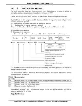
- 1. 8086 INSTRUCTION FORMATS Compiled by: L. Krishnananda, Assistant Professor, REVA ITM, Bangalore 1 Byte 3 Byte 4 UNIT 2. Instruction Format: The 8086 instruction sizes vary from one to six bytes. Depending on the type of coding, an instruction may have more than one Hexcode, (not unique as in 8085) The OP code field occupies 6-bits.It defines the operation to be carried out by the instruction. Register Direct bit (D) occupies one bit. It defines whether the register operand in byte 2 is the source or destination operand. D=1 Specifies that the register operand is the destination operand. D=0 indicates that the register is a source operand. Data size bit (W) defines whether the operation to be performed is an 8 bit or 16 bit data W=0 indicates 8 bit operation W=1 indicates 16 bit operation 7 2 1 0 7 6 5 4 3 2 1 0 Opcode D W MOD REG R/M Low Disp/ DATA High Disp/ DATA The second byte of the instruction usually identifies whether one of the operands is in memory or whether both are registers. This byte contains 3 fields. These are the mode (MOD) field, the register (REG) field and the Register/Memory (R/M) field. MOD (2 bits) Interpretation 00 Memory mode with no displacement follows except for 16 bit displacement when R/M=110 01 Memory mode with 8 bit displacement 10 Memory mode with 16 bit displacement 11 Register mode (no displacement) Register field occupies 3 bits. It defines the register for the first operand which is specified as source or destination by the D bit. Register Codes: Byte 1 Byte 2 OR Register Operand/Register to use EA Calculation Register Operand/Extension of opcode Register mode/Memory mode with displacement length Word/byte operation Direction is to register/from register Operation code DIRECT ADDRESS LOW BYTE DIRECT ADDRESS HIGH BYTE
- 2. 8086 INSTRUCTION FORMATS Compiled by: L. Krishnananda, Assistant Professor, REVA ITM, Bangalore 2 REG W=0 W=1 000 AL AX 001 CL CX 010 DL DX 011 BL BX 100 AH SP 101 CH BP 110 DH SI 111 BH DI The R/M field occupies 3 bits. The R/M field along with the MOD field defines the second operand as shown below. MOD 11 R/M W=0 W=1 000 AL AX 001 CL CX 010 DL DX 011 BL BX 100 AH SP 101 CH BP 110 DH SI 111 BH DI Effective Address Calculation R/M MOD=00 MOD 01 MOD 10 000 (BX) + (SI) (BX)+(SI)+D8 (BX)+(SI)+D16 001 (BX)+(DI) (BX)+(DI)+D8 (BX)+(DI)+D16 010 (BP)+(SI) (BP)+(SI)+D8 (BP)+(SI)+D16 011 (BP)+(DI) (BP)+(DI)+D8 (BP)+(DI)+D10 100 (SI) (SI) + D8 (SI) + D16 101 (DI) (DI) + D8 (DI) + D16 110 Direct address (BP) + D8 (BP) + D16 111 (BX) (BX) + D8 (BX) + D16 In the above, encoding of the R/M field depends on how the mode field is set. If MOD=11 (register to register mode), this R/M identifies the second register operand. MOD selects memory mode, then R/M indicates how the effective address of the memory operand is to be calculated. Bytes 3 through 6 of an instruction are optional fields that MOD / R/M Memory Mode (EA Calculation) Register Mode 00 01 10 W=0 W=1 000 (BX)+(SI) (BX)+(SI)+d8 (BX)+(SI)+d16 AL AX 001 (BX) + (DI) (BX)+(DI)+d8 (BX)+(DI)+d16 CL CX 010 (BP)+(SI) (BP)+(SI)+d8 (BP)+(SI)+d16 DL DX 011 (BP)+(DI) (BP)+(DI)+d8 (BP)+(DI)+d16 BL BX 100 (SI) (SI) + d8 (SI) + d16 AH SP 101 (DI) (DI) + d8 (DI) + d16 CH BP 110 d16 (BP) + d8 (BP) + d16 DH SI 111 (BX) (BX) + d8 (BX) + d16 BH DI
- 3. 8086 INSTRUCTION FORMATS Compiled by: L. Krishnananda, Assistant Professor, REVA ITM, Bangalore 3 normally contain the displacement value of a memory operand and / or the actual value of an immediate constant operand. Obtain the opcodes for the following instructions. Example 1 : Code for MOV CH, BL This instruction transfers 8 bit content of BL into CH The 6 bit Opcode for this instruction is 1000102 D bit indicates whether the register specified by the REG field of byte 2 is a source or destination operand. D=0 indicates BL is a source operand. W=0 byte operation In byte 2, since the second operand is a register MOD field is 112. The R/M field = 101 (CH) Register (REG) field = 011 (BL) Hence the machine code for MOV CH, BL is 10001000 11 011 101 Byte 1 Byte2 = 88DDH Example 2: Code for SUB BX, (DI) This instruction subtracts the 16 bit content of memory location addressed by DI and DS from Bx. The 6 bit Opcode for SUB is 0010102. D=1 so that REG field of byte 2 is the destination operand. W=1 indicates 16 bit operation. MOD = 00 REG = 011 R/M = 101 The machine code is 0010 1011 0001 1101 2 B 1 D Example 3 :Code for MOV 1234 (BP), DX Here we have specify DX using REG field, the D bit must be 0, indicating the DX is the source register. The REG field must be 010 to indicate DX register. The W bit must be 1 to indicate it is a word operation. 1234 [BP] is specified using MOD value of 10 and R/M value of 110 and a displacement of 1234H. The 4 byte code for this instruction would be 89 96 34 12H. Opcode D W MOD REG R/M LB displacement HB displacement 100010 0 1 10 010 110 34H 12H Example 4 :Code for MOV DS : 2345 [BP], DX Here we have to specify DX using REG field. The D bit must be 0, indicating that Dx is the source register. The REG field must be 010 to indicate DX register. The w bit must be 1 to indicate it is a word operation. 2345 [BP] is specified with MOD=10 and R/M = 110 and displacement = 2345 H. Whenever BP is used to generate the Effective Address (EA), the default segment would be SS. In this example, we want the segment register to be DS, we have to provide the
- 4. 8086 INSTRUCTION FORMATS Compiled by: L. Krishnananda, Assistant Professor, REVA ITM, Bangalore 4 segment override prefix byte (SOP byte) to start with. The SOP byte is 001 xx 110, where SR value is provided as per table shown below. xx Segment register 00 ES 01 CS 10 SS 11 DS To specify DS register, the SOP byte would be 001 11 110 = 3E H. Thus the 5 byte code for this instruction would be 3E 89 96 45 23 H. SOP Opcode D W MOD REG R/M LB disp. HD disp. 3EH 1000 10 0 1 10 010 110 45 23 Suppose we want to code MOV SS : 2345 (BP), DX. This generates only a 4 byte code, without SOP byte, as SS is already the default segment register in this case. Example 5: Give the instruction template and generate code for the instruction ADD 0FABE [BX], [DI], DX (code for ADD instruction is 000000) ADD 0FABE [BX] [DI], DX Here we have to specify DX using REG field. The bit D is 0, indicating that DX is the source register. The REG field must be 010 to indicate DX register. The w must be 1 to indicate it is a word operation. FABE (BX + DI) is specified using MOD value of 10 and R/M value of 001 (from the summary table). The 4 byte code for this instruction would be Opcode D W MOD REG R/M 16 bit disp. 000000 0 1 10 010 001 BEH FAH =01 91 BE FAH Example 6 : Give the instruction template and generate the code for the instruction MOV AX, [BX] (Code for MOV instruction is 100010) AX destination register with D=1 and code for AX is 000 [BX] is specified using 00 Mode and R/M value 111. It is a word operation Opcode D W Mod REG R/M 100010 1 1 00 000 111 =8B 07H INPUT/OUTPUT INSTRUCTIONS: IN acc, port : In transfers a byte or a word from input port to the AL register or the AX register respectively. The port number my be specified either with an immediate byte constant, allowing access to ports numbered 0 through 255 or with a number previously placed in the DX register allowing variable access (by changing the value in DX) to ports numbered from 0 through 65,535. In Operands Example acc, immB IN AL, 0E2H (OR) IN AX, PORT acc, DX IN AX, DX (OR) IN AL, DX
- 5. 8086 INSTRUCTION FORMATS Compiled by: L. Krishnananda, Assistant Professor, REVA ITM, Bangalore 5 OUT port, acc : Out transfers a byte or a word from the AL register or the AX register respectively to an output port. The port numbers may be specified either with an immediate byte or with a number previously placed in the register DX allowing variable access. No flags are affected. In Operands Example Imm 8, acc OUT 32, AX (OR) OUT PORT, AL DX, acc OUT DX, AL (OR) OUT DX, AX I/O mode (direct) : Port number is an 8 bit immediate operand. Example : OUT 05 H, AL Outputs [AL] to 8 bit port 05 H I/O mode (indirect): The port number is taken from DX. Example 1 : INAL, DX If [DX] = 5040 8 bit content by port 5040 is moved into AL. Example 2 : IN AX, DX Inputs 8 bit content of ports 5040 and 5041 into AL and AH respectively.