SlideShare une entreprise Scribd logo
1  sur  150
Télécharger pour lire hors ligne
Bifurcation analysis of a semiconductor laser
  with two filtered optical feedback loops


                                       ´
                      Piotr Marek Słowinski
              Department of Engineering Mathematics
                         University of Bristol


        A dissertation submitted to the University of Bristol in
          accordance with the requirements of the degree of
        Doctor of Philosophy in the Faculty of Engineering.


                              May 2011
Abstract


    We study the solution structure and dynamics of a semiconductor laser receiving delayed
filtered optical feedback from two filter loops; this system is also referred to as the 2FOF laser.
The motivation for this study comes from optical communication applications where two filters
are used to control and stabilize the laser output. The overall mathematical model of the 2FOF
laser takes the form of delay differential equations for the (real-valued) inversion of the laser,
and the (complex-valued) electric fields of the laser and of the two filters. There are two time
delays that arise from the travel times from the laser to each of the filters and back.
     Since, in the optical communication applications the main concern is stable operation of
the laser source, in our analysis we focus on the continuous-wave solutions of the 2FOF laser.
These basic solutions are known as external filtered modes (EFMs), and they have been studied
for the case of a laser with only a single filtered optical feedback loop. Nevertheless, compared
to the single FOF laser, the introduction of the second filter significantly influences the structure
and stability of the EFMs and, therefore, the laser’s operation.
     To analyse the structure and stability of the EFMs we compute and represent them as an
EFM surface in (ωs , dCp , Ns )-space of frequency ωs , filter phase difference dCp , and popu-
lation inversion Ns of the laser. The parameter dCp is a measure of the interference between
the two filter fields, and it is identified as a key to the EFM structure. To analyse how the struc-
ture and stability of the EFMs depend on all the filter and feedback loop parameters, we make
extensive use of numerical continuation techniques for delay differential equations and asso-
ciated transcendental equations. Furthermore, we use singularity theory to explain changes of
the EFM surface in terms of the generic transitions through its critical points. Presented in this
work is a comprehensive picture of the dependence of the EFM surface and associated EFM
stability regions on all filter and feedback loop parameters. Our theoretical results allow us to
make certain predictions about the operation of a real 2FOF laser device. Furthermore, they
show that many other laser systems subject to optical feedback can be considered as limiting
cases of the 2FOF laser.
    Overall, the EFM surface is the natural object that one should consider to understand dy-
namical properties of the 2FOF laser. Our geometric approach allows us to perform a multi-
parameter analysis of the 2FOF laser model and provides a compact way of understanding
the EFM solutions. More generally, our study showcases the state-of-the-art of what can be
achieved in the study of delay equations with considerable number of parameters with ad-
vanced tools of numerical bifurcation analysis.
Acknowledgements


   First of all, I would like to thank my supervisors Prof. Bernd Krauskopf and Dr. Sebastian
M. Wieczorek. Their support and encouragement made my PhD project and stay in Bristol a
great experience, and their wise guidance made an invaluable contribution to my research and
development. Additional thanks go to Dr. Harmut Erzgräber. His published works, as well as
private communication, helped me to establish my research project. Furthermore, I would like
to thank Prof. Dirk Roose and Dr. David A. W. Barton, who agreed to review my dissertation.

   I greatly appreciate all financial support I received during my PhD. The Great Western
Research Initiative funded my PhD research under studentship number 250, with support from
Bookham Technology PLC (now Oclaro Inc.). The Bristol Center for Applied Nonlinear Math-
ematics provided support during the write-up of this thesis. The Society for Industrial and Ap-
plied Mathematics granted me a SIAM Student Travel Award to attend the SIAM Conference
on Applications of Dynamical Systems in May 2009 at Snowbird, Utah. The European Com-
mission Marie Curie fellowship supported my attendance at the TC4 SICON event in Lyon,
France, in March 2009. The Centre de Recherches Mathématiques supported my attendance
at the workshop and mini-conference on "Path Following and Boundary Value Problems" in
Montréal, Canada, in July 2007.

   Finally, I would like to thank the Department of Engineering Mathematics and the Uni-
versity of Bristol for providing a creative environment and supporting all my other research
activities. During my stay at the Applied Nonlinear Mathematics research group I met many
inspiring people who became my friends and colleagues. For this I am especially grateful.
“The mathematical description of the world depends on a delicate interplay between discrete
 and continuous objects. Discrete phenomena are perceived first, but continuous ones have a
simpler description in terms of the traditional calculus. Singularity theory describes the birth
                                         of discrete objects from smooth, continuous sources.

   The main lesson of singularity theory is that, while the diversity of general possibilities is
  enormous, in most cases only some standard phenomena occur. It is possible and useful to
   study those standard phenomena once for all times and recognize them as the elements of
        more complicated phenomena, which are combinations of those standard elements.”
                                                                                    V.I. Arnold
Author’s Declaration


    I declare that the work in this dissertation was carried out in accordance with the require-
ments of the University’s Regulations and Code of Practice for Research Degree Programmes
and that it has not been submitted for any other academic award. Except where indicated by
specific reference in the text, the work is the candidate’s own work. Work done in collabora-
tion with, or with the assistance of, others, is indicated as such. Any views expressed in the
dissertation are those of the author.


Signed:


Dated:
Contents


1   Introduction                                                                                   1
    1.1   Modelling the 2FOF laser . . . . . . . . . . . . . . . . . . . . . . . . . . . . .       5
    1.2   Outline of the thesis . . . . . . . . . . . . . . . . . . . . . . . . . . . . . . . .    8

2   Classification of EFM structure                                                                11
    2.1   External filtered modes . . . . . . . . . . . . . . . . . . . . . . . . . . . . . . 12
          2.1.1    EFM components . . . . . . . . . . . . . . . . . . . . . . . . . . . . . 15
          2.1.2    EFM components for two identical filters . . . . . . . . . . . . . . . . 17
    2.2   The EFM-surface . . . . . . . . . . . . . . . . . . . . . . . . . . . . . . . . . 19
    2.3   Classification of the EFM surface for dτ = 0 . . . . . . . . . . . . . . . . . . 24
          2.3.1    Dependence of the EFM components for fixed dCp = 0 on the detunings 25
          2.3.2    EFM surface types with dCp -independent number of EFM components               30
          2.3.3    Transitions of the EFM surface . . . . . . . . . . . . . . . . . . . . . . 33
          2.3.4    The EFM surface bifurcation diagram in the (∆1 , ∆2 )-plane for fixed Λ 41
    2.4   Dependence of the EFM surface bifurcation diagram on the filter width Λ . . . 52
          2.4.1    Unfolding of the bifurcation at infinity . . . . . . . . . . . . . . . . . . 55
          2.4.2    Islands of non-banded EFM surface types . . . . . . . . . . . . . . . . 56
    2.5   The effect of changing the delay difference ∆τ . . . . . . . . . . . . . . . . . 59
    2.6   Conclusion and outlook . . . . . . . . . . . . . . . . . . . . . . . . . . . . . . 62

3   EFM stability regions                                                                         65
    3.1   Dependence of EFM stability on κ . . . . . . . . . . . . . . . . . . . . . . . . 67
    3.2   Dependence of EFM stability on Λ . . . . . . . . . . . . . . . . . . . . . . . . 70
    3.3   Dependence of EFM stability on ∆ . . . . . . . . . . . . . . . . . . . . . . . . 77
          3.3.1    Influence of hole creation on EFM stability . . . . . . . . . . . . . . . 79
          3.3.2    Influence of SN -transition on EFM stability . . . . . . . . . . . . . . . 86
          3.3.3    Influence of Sω -transition on EFM stability . . . . . . . . . . . . . . . 89
          3.3.4    Influence of SC -transition on EFM stability . . . . . . . . . . . . . . . 94
    3.4   Dependence of EFM stability on dτ . . . . . . . . . . . . . . . . . . . . . . . 97
    3.5   Different types of bifurcating oscillations . . . . . . . . . . . . . . . . . . . . 100


                                                 i
CONTENTS                                                                                       ii


4   Overall summary                                                                          105
    4.1   Physical relevance of findings . . . . . . . . . . . . . . . . . . . . . . . . . . 107
          4.1.1   Experimental techniques for the control of parameters . . . . . . . . . 107
          4.1.2   Expected experimental results . . . . . . . . . . . . . . . . . . . . . . 108
          4.1.3   Existence of multistability . . . . . . . . . . . . . . . . . . . . . . . . 110

Bibliography                                                                                 113

Appendices                                                                                   121

A How to construct the EFM surface                                                           121
    A.1 Dealing with the S1 -symmetry of the 2FOF laser model . . . . . . . . . . . . . 122
    A.2 Computation and rendering of the EFM surface . . . . . . . . . . . . . . . . . 123
    A.3 Determining the stability of EFMs . . . . . . . . . . . . . . . . . . . . . . . . 125
List of Tables


 1.1   System parameters and their values. . . . . . . . . . . . . . . . . . . . . . . .   7

 2.1   Notation and parameter values for the types of EFM-surface in figure 2.11.
       The second and third column show the minimal number Cmin and the maximal
       number Cmax of EFM components (for suitable fixed dCp ) of the type; note
       that in all cases the number of EFM components is independent of dC p . . . . . 33
 2.2   Notation and parameter values for the types of EFM-surface in figure 2.18;
       the second and third column show the minimal number Cmin and the maximal
       number Cmax of EFM components (for suitable fixed dCp ) of the type. . . . . . 44
 2.3   Notation and parameter values for the types of EFM-surface in figure 2.21;
       the second and third column show the minimal number Cmin and the maximal
       number Cmax of EFM components (for suitable fixed dCp ) of the type. . . . . . 48

 3.1   Axes ranges for all the panels in figure 3.6 . . . . . . . . . . . . . . . . . . . . 81


                                            iii
List of Figures


 1.1   Sketch of a 2FOF semiconductor laser realized by coupling to an optical fiber
       with two fibre Bragg gratings (a), and by two (unidirectional) feedback loops
       with Fabry-Pérot filters (b); other optical elements are beam splitters (BS) and
       optical isolators (ISO). . . . . . . . . . . . . . . . . . . . . . . . . . . . . . .   3
 1.2   Spectrum of light transmitted (left scale) or reflected (right scale) by a Fabry-
       Pérot filter (black) and by a fibre Bragg grating (grey). The peak is at the filter’s
       central frequency ∆, and the filter width Λ is defined as the full width at half
       maximum. . . . . . . . . . . . . . . . . . . . . . . . . . . . . . . . . . . . . .     4

 2.1   The graph of (2.3) (black curve) oscillates between its envelope (grey curve)
       given by (2.9). Frequencies of EFMs (blue dots) are found from intersection
       points of the graph of Ω(ωs ) with the diagonal; also shown are the intersection
                                                    1       2
       points (black dots) with the envelope. Here Cp = 0, Cp = π/3, ∆1 = −0.1,
       ∆2 = 0.05, κ1 = 0.05, κ2 = 0.025, Λ1 = Λ2 = 0.005, τ1 = 500 and τ2 = 400. 13
 2.2                                                                                 1
       Projection of EFMs branches onto the (ωs , Ns )-plane (a) and onto the (ωs , Cp )-
       plane (b). The open circles are the starting points for three different types of
       branches. The blue branch is the EFM component for dCp = 0, the green
                                  1
       branches are for constant Cp , and the red branches are for constant ωs . Here
       ∆1 = ∆2 = 0, κ1 = κ2 = 0.05, Λ1 = Λ2 = 0.015, dτ1 = τ2 = 500 and the
       other parameters are as given in Table 1.1. . . . . . . . . . . . . . . . . . . . . 18
 2.3                                                    1
       Representation of the EFM surface in (ωs , Ns , Cp )-space; compare with fig-
       ure 2.2. Panel (a) shows one fundamental element of the EFM surface (semi-
       transparent grey); superimposed are the EFM branches from figure 2.2. The
       entire EFM surface is a single smooth surface that is obtain by connecting all
       2nπ-translated copies of the surface element shown in panel (a). Panels (b) and
                                                   1
       (c) show how the EFM branches for constant Cp and for constant ωs , respec-
       tively, arise as intersection curves of fixed sections with the EFM surface. . . . 20


                                             iv
LIST OF FIGURES                                                                               v


  2.4   Representation of the EFM surface of figure 2.3 in (ωs , Ns , dCp )-space. Panel
        (a) shows one fundamental 2π interval of the EFM surface (semitransparent
        grey); superimposed are the EFM branches from figure 2.2. The entire EFM
        surface consists of all 2nπ-translated copies of this compact surface, which
        touch at the points (ωs , Ns , dCp ) = (0, 0, (2n + 1)π); panel (b) shows this
        in projection of the surface onto the (ωs , dCp )-plane. Panel (c) illustrates how
        the EFM branches for constant ωs and the outer-most EFM component for
        dCp = 2nπ arise as intersection curves with planar sections. . . . . . . . . . . 22
  2.5   EFM-components arising as sections through the EFM surface of figure 2.4.
        Panel (a) shows the EFM-surface in (ωs , Ns , dCp )-space, intersected with the
        planes defined by dCp = 0 and dCp = 0.9π, respectively. Panels (b1) and
        (c1) show the corresponding envelope (grey curves) given by (2.9). The black
                                                  1
        solution curve of (2.3) inside it is for Cp = 0; it gives rise to the marked blue
        EFMs. Panels (b2) and (c2) show the two respective EFM-components and
        individual EFMs (blue dots) in the (ωs , dCp )-plane. . . . . . . . . . . . . . . . 23
  2.6   Envelope and solution curve for dCp = 0 (a1)-(d1) and the corresponding
        EFM-components and EFMs (blue dots) of the 2FOF laser, were ∆1 = 0.2 is
        fixed and in panels (a)-(d) ∆2 takes the values −0.2, 0, 0.158 and 0.2, respec-
        tively; here Λ1 = Λ2 = 0.015, τ1 = τ2 = 500 and the other parameters are as
        given in Table 1.1. . . . . . . . . . . . . . . . . . . . . . . . . . . . . . . . . . 26
  2.7   Regions in the (∆1 , ∆2 )-plane with a one, two or three EFM components of
        the 2FOF laser for dCp = 0. From (a) to (f) Λ takes the values Λ = 0, Λ =
        0.001, Λ = 0.01, Λ = 0.06, Λ = 0.12 and Λ = 0.14. . . . . . . . . . . . . . . 28
  2.8   Panel (a) shows surfaces (orange and grey) that divide the (∆1 , ∆2 , Λ)-space
        into regions with one, two and three EFM-components of the 2FOF laser for
        dCp = 0; in the shown (semitransparent) horizontal cross section for Λ = 0.01
        one finds the bifurcation diagram from figure 2.7 (c) . Panel (b) shows the
        bifurcation diagram in the (∆1 , Λ)-plane for fixed ∆2 = 0.82; the light grey
        curve is the boundary curve for the limiting single FOF laser for ∆2 = ∞.
        Panel (c) shows the projection onto the (∆1 , Λ)-plane of the section along the
        diagonal ∆1 = ∆2 through the surfaces in panel (a). . . . . . . . . . . . . . . 30
  2.9   The EFM surface in (ωs , dCp , Ns )-space showing case B for ∆1 = ∆2 = 0
        (a), and showing case B BB for ∆1 = 0.16, ∆2 = −0.16 (b), where Λ = 0.015. 31
LIST OF FIGURES                                                                            vi


  2.10 Boundary curves (orange or grey) in the (∆1 , ∆2 )-plane for Λ = 0.01 for
       61 equidistant values of dCp from the interval [−π, π]; compare with fig-
       ure 2.7 (c). In the white regions the 2FOF laser has one, two or three EFM
       components independently of the value of dCp , as is indicated by the labelling
       with symbols B and B; representatives of the four types of EFM components
       can be found in figure 2.11. . . . . . . . . . . . . . . . . . . . . . . . . . . . . 32
  2.11 The four simple banded types of EFM-surface of the 2FOF laser in the la-
       belled regions of figure 2.10, represented by the projection (shaded) onto the
       (ωs , dCp )-plane; the blue boundary curves are found directly from (2.16). For
       notation and the corresponding values of ∆1 and ∆2 see Table 2.1; in all panels
       ωs ∈ [−0.3, 0.3] and dCp ∈ [−π, π]. . . . . . . . . . . . . . . . . . . . . . . 33
  2.12 Minimax transition M of the EFM-surface in (ωs , dCp , Ns )-space, where a
       connected component of the EFM surface (a1) shrinks to a point (b1). Panels
       (a2) and (b2) show the corresponding projection onto the (ωs , dCp )-plane of
       the entire EFM surface; the local region where the transition M occurs is high-
       lighted by dashed lines and the projections of the part of the EFM surface in
       panels (a1) and (b1) is shaded grey. Here Λ = 0.01, ∆1 = 0.4, and ∆2 = 0.28
       in (a) and ∆2 = 0.28943 in (b). . . . . . . . . . . . . . . . . . . . . . . . . . . 36
  2.13 Saddle transition SC of the EFM-surface in (ωs , dCp , Ns )-space, where lo-
       cally the surface changes from a one-sheeted hyperboloid (a1) to a cone aligned
       in the dCp -direction (b1) to a two-sheeted hyperboloid (c1). Panels (a2)–
       (c2) show the corresponding projection onto the (ωs , dCp )-plane of the entire
       EFM surface; the local region where the transition SC occurs is highlighted
       by dashed lines and the projections of the part of the EFM surface in panels
       (a1)–(c1) is shaded grey. Here Λ = 0.01, ∆1 = 0.4, and ∆2 = 0.23 in (a),
       ∆2 = 0.232745 in (b) and ∆2 = 0.24 in (c). . . . . . . . . . . . . . . . . . . . 37
  2.14 Saddle transition Sω of the EFM-surface in (ωs , dCp , Ns )-space, where a con-
       nected component (a1) pinches (b1) and then locally disconnects (c1); here the
       associated local cone in panel (b1) is aligned in the ωs -direction. Panels (a2)–
       (c2) show the corresponding projection onto the (ωs , dCp )-plane of the entire
       EFM surface; the local region where the transition Sω occurs is highlighted
       by dashed lines and the projections of the part of the EFM surface in panels
       (a1)–(c1) is shaded grey. Here Λ = 0.01, ∆1 = 0.4, and ∆2 = 0.13 in (a),
       ∆2 = 0.133535 in (b) and ∆2 = 0.135 in (c). . . . . . . . . . . . . . . . . . . 38
LIST OF FIGURES                                                                            vii


  2.15 Saddle transition SN of the EFM-surface in (ωs , dCp , Ns )-space, where two
       sheets that lie on top of each other in the Ns direction (a1) connect at a point
       (b1) and then create a hole in the surface (c1); here the associated local cone
       in panel (b1) is aligned in the N -direction. Panels (a2)–(c2) show the corre-
       sponding projection onto the (ωs , dCp )-plane of the entire EFM surface; the
       local region where the transition SN occurs is highlighted by dashed lines and
       the projections of the part of the EFM surface in panels (a1)–(c1) is shaded
       grey. Here Λ = 0.01, ∆1 = 0.4, and ∆2 = 0.0.11 in (a), ∆2 = 0.11085 in (b)
       and ∆2 = 0.1115 in (c). . . . . . . . . . . . . . . . . . . . . . . . . . . . . . 39
  2.16 Cubic tangency C of the EFM-surface in (ωs , dCp , Ns )-space, where a part
       of the surface (a1) becomes tangent to a plane {dCp = const} (b1) and then
       develops a bulge (c1). The unfolding of the cubic tangency into two dCp -folds
       can be seen clearly in the projections onto the (ωs , dCp )-plane in panels (a2)–
       (c2). Here Λ = 0.015, and (∆1 , ∆2 ) = (−0.03, −0.0301) in (a), (∆1 , ∆2 ) =
       (−0.04, −0.0401) in (b) and (∆1 , ∆2 ) = (−0.05, −0.051). . . . . . . . . . . . 40
  2.17 EFM surface bifurcation diagram in the (∆1 , ∆2 )-plane for Λ = 0.01 with
       regions of different types of the EFM surface; see figure 2.18 for representa-
       tives of the labelled types of the EFM surface and Table 2.2 for the notation.
       The main boundary curves are the singularity transitions M (orange curves),
       SC (blue curves), Sω (green curves) and SN (red curves). The locus of cu-
       bic tangency (black curves) can be found near the diagonal; also shown is the
       anti-diagonal. . . . . . . . . . . . . . . . . . . . . . . . . . . . . . . . . . . . 42
  2.18 Additional types of EFM-surface of the 2FOF laser in the labelled regions of
       figure 2.17, represented by the projection (shaded) onto the (ωs , dCp )-plane;
       the blue boundary curves are found directly from (2.16). For notation and
       the corresponding values of ∆1 and ∆2 see Table 2.2; in all panels ωs ∈
       [−0.3, 0.3] and dCp ∈ [−π, π]. . . . . . . . . . . . . . . . . . . . . . . . . . 43
  2.19 Projection of the EFM-surface onto (ωs , dCp )-plane for Λ = 0.01. Panel (a) is
       for ∆1 = −∆2 = 0.003 and panel (b) is for ∆1 = −∆2 = 0.08. . . . . . . . . 45
  2.20 Enlargement near the center of the (∆1 , ∆2 )-plane of figure 2.17 with (blue)
       curves of SC transition, (red) curves of SN transition, and (black) curves Ca
       and (grey) curves Cd of cubic tangency; see figure 2.21 for representatives of
       the labelled types of the EFM surface and Table 2.3 for the notation. . . . . . . 46
LIST OF FIGURES                                                                             viii


  2.21 Additional types of EFM-surface of the 2FOF laser that feature bulges, repre-
       sented by the projection (shaded) onto the (ωs , dCp )-plane; the blue boundary
       curves are found directly from (2.16). Where necessary, insets show local en-
       largements. The corresponding regions in the (∆1 , ∆2 )-plane can be found in
       figures 2.20, 2.25 and 2.29; for notation and the corresponding values of ∆1 ,
       ∆2 and Λ see Table 2.3. In all panels ωs ∈ [−0.3, 0.3] and dCp ∈ [−π, π]. . . 47
  2.22 Global manifestation of local saddle transition SC of the EFM-surface where
       two bulges connect to form a hole. Panels (a1)–(c1) show the relevant part of
       the EFM surface and panels (a2)–(c2) the corresponding projection onto the
       (ωs , dCp )-plane. Here Λ = 0.015 and ∆2 = −0.02, and ∆1 = −0.0248 in
       (a), ∆1 = −0.02498 in (b) and ∆1 = −0.0252 in (c). . . . . . . . . . . . . . . 49
  2.23 Sketch of the bifurcation diagram in the (∆1 , ∆2 )-plane near the (purple)
       codimension-two point DCN C on the curve C of cubic tangency, from which
       the (red) curve SN and the (blue) curve SC of saddle transition emanate; com-
       pare with figures 2.20 and 2.29 (a) and (b). . . . . . . . . . . . . . . . . . . . . 50
  2.24 Sketch of the bifurcation diagram in the (∆1 , ∆2 )-plane near the (golden)
       codimension-two point DCM ω on the curve C of cubic tangency, from which
       the (orange) curve M and the (green) curve Sω of saddle transition emanate;
       compare with figures 2.17 and 2.28. . . . . . . . . . . . . . . . . . . . . . . . 50
  2.25 Enlargement near the diagonal of the (∆1 , ∆2 )-plane with (blue) curves of SC
       transition, (green) curves of Sω transition, and SC transition, and (black) curves
       Cd of cubic tangency; see figure 2.21 for representatives of the labelled types
       of the EFM surface and Table 2.3 for the notation. Panel (a) is for Λ = 0.01 as
       figure 2.17, and panel (b) is for Λ = 0.02 . . . . . . . . . . . . . . . . . . . . 52
  2.26 EFM surface bifurcation diagram in the compactified (∆1 , ∆2 )-square, [−1, 1]×
       [−1, 1], showing regions of band-like EFM surface types; compare with fig-
       ure 2.10. The boundary of the square corresponds to ∆i = ±∞; from (a) to
       (e) Λ takes values Λ = 0.01, Λ = 0.015, Λ = 0.06, Λ = 0.098131, Λ = 0.1
       and Λ = 0.13. . . . . . . . . . . . . . . . . . . . . . . . . . . . . . . . . . . . 53
  2.27 Sketch of EFM surface bifurcation diagram near the boundary {∆2 = −1} of
       the (∆1 , ∆2 )-square in the transition through Λ = ΛC . Panels (a1)–(a3) show
       the transition involving the (black) curve Ca of cubic tangency that bounds the
       orange islands, and panels (b1)–(b3) show the transition involving the (grey)
       curve Cd of cubic tangency that bounds the grey islands; compare with fig-
       ure 2.26 (c)–(e). . . . . . . . . . . . . . . . . . . . . . . . . . . . . . . . . . . 55
  2.28 Grey island for Λ = 0.1 in the (∆1 , ∆2 )-plane with regions of non-banded
       EFM surface types; compare with figure 2.26 (e). . . . . . . . . . . . . . . . . 56
LIST OF FIGURES                                                                              ix


  2.29 Orange island in the (∆1 , ∆2 )-plane with regions of non-banded EFM surface
        types; the inset in panel (a) shows the details of curves and regions. From (a)
        to (d) Λ takes the values Λ = 0.1, Λ = 0.145, Λ = 0.166 and Λ = 0.179;
        compare panel (a) with figure 2.26 (e). . . . . . . . . . . . . . . . . . . . . . . 58
  2.30 The EFM surface (a) for κ = 0.05, ∆1 = ∆2 = 0, Λ = 0.015, and τ1 = 500
        and τ2 = 600 so that dτ = 100, and its intersection with the planes defined by
        dCp = 0 and dCp = −π; compare with figure 2.5. Panels (b)–(e) show the
        EFM-components for dCp = 0, dCp = −π/2, dCp = −π and dCp = −3π/2,
                                                      1
        respectively; the blue dots are the EFMs for Cp as given by (2.12). . . . . . . . 60
  2.31 Solution curves of the transcendental equation (2.3) and corresponding EFM
                                                                         1
        components for dCp = 0, where the dots show the actual EFMs for Cp =0;
        here κ = 0.05, ∆1 = ∆2 = 0, Λ = 0.015, τ1 = 500, and dτ = 200 in panels
        (a) and dτ = 300 in panels (b). The inset of panel (b2) shows that the EFM
        components are in fact disjoint. . . . . . . . . . . . . . . . . . . . . . . . . . . 61
  2.32 The EFM surface of type hBB for dτ = 0 (a1) and its EFM components for
        dCp = −1.6π (a2), and the corresponding sheared EFM surface for dτ = 230
        (b1) and its EFM components for dCp = −1.6π (b2). Here κ = 0.05, ∆1 =
        0.13, ∆2 = −0.1, Λ = 0.01, and τ1 = 500. . . . . . . . . . . . . . . . . . . . 62

  3.1   Dependence of the EFM surface on the feedback rate κ (as indicated in the
        panels); here ∆1 = ∆2 = 0, Λ = 0.015 and dτ = 0. Panels (a1)–(c1)
        show the EFM-surface in (ωs , Ns , dCp )-space (semitransparent grey) together
        with information about the stability of the EFMs. Panels (a2)–(c2) show cor-
        responding projections of the EFM surface onto the (ωs , Ns )-plane and pan-
        els (a3)–(c3) onto the (ωs , dCp )-plane. Regions of stable EFMs (green) are
        bounded by Hopf bifurcations curves (red) and saddle node bifurcation curves
        (blue). In panels (a1)–(c1) ωs ∈ [−0.065, 0.065], dCp /π ∈ [−1, 1] and
        Ns ∈ [−0.013, 0.013]. . . . . . . . . . . . . . . . . . . . . . . . . . . . . . . 69
  3.2   Dependence of the EFM surface on the filter width Λ = Λ1 = Λ2 (as in-
        dicated); here ∆1 = ∆2 = 0, κ = 0.01 and dτ = 0. Light grey regions
        with black envelopes are projections, for five different values of Λ, of the EFM
        surface onto the (ωs , Ns )-plane. . . . . . . . . . . . . . . . . . . . . . . . . . 70
LIST OF FIGURES                                                                             x


  3.3   Dependence of the stability region on the EFM surface on the common filter
        width Λ (as indicated in the panels); here ∆1 = ∆2 = 0, κ = 0.01 and dτ = 0.
        Panels (a1)–(d1) show the EFM-surface in (ωs , Ns , dCp )-space (semitrans-
        parent grey) together with information about the stability of the EFMs. Pan-
        els (a2)–(d2) show corresponding projections of the EFM surface onto the
        (ωs , Ns )-plane. Black dots indicate codimension-two Bogdanov-Takens bi-
        furcation points; curves and regions are coloured as in figure 3.1. In panels
        (a1)–(d1) dCp ∈ [−π, π], and the ranges of Ns and ωs are as in panels (a2)–(d2). 72
  3.4   Projections of the EFM surfaces presented in figure 3.3 (a1)–(d1) onto the
        (ωs , dCp )-plane. Black dots indicate codimension-two Bogdanov-Takens bi-
        furcation points; curves and regions are coloured as in figure 3.1. . . . . . . . . 73
  3.5   Projections of the EFM surface onto the (ωs , Ns )-plane, for increasing filter
        width Λ as indicated in the panels; here ∆1 = ∆2 = 0, κ = 0.01 and dτ =
        0. Black dots indicate codimension-two Bogdanov-Takens bifurcation points;
        curves and regions are coloured as in figure 3.1. . . . . . . . . . . . . . . . . . 75
  3.6   Influence of local saddle transition SC , where two bulges connect to form a
        hole, on the stability of the EFMs; here ∆2 = 0, κ = 0.01, Λ = 0.005 and
        dτ = 0. Panels (a1)–(c1) shows two copies of the fundamental 2π-interval
        of the EFM surface for different values of a detuning ∆1 , as indicated in the
        panels. Panels (a2)–(c2) show enlargements of the region where the hole is
        formed. In panels (a1)–(c1) the limit of the dCp -axis corresponds to a planar
        section that goes through middle of the hole in panels (a2)–(c2). For the spe-
        cific axes ranges see Table 3.1; curves and regions are coloured as in figure 3.1.   80
  3.7   Projections with stability information of the EFM surface in figure 3.6 onto
        the (ωs , dCp )-plane, shown for increasing filter detuning ∆1 = 0.0005 (a),
        ∆1 = 0.0007 (b) and ∆1 = 0.005 (c); here ∆2 = 0, κ = 0.01, Λ = 0.005 and
        dτ = 0. To illustrate the changes in the EFM surface, panels (a1)–(c1) show
        the 2π interval of the EFM surface that is shifted by π with respect to the fun-
        damental 2π interval of the EFM-surface. Panels (a2)–(c2) show enlargements
        of the central part of panels (a1)–(c1). Curves and regions are coloured as in
        figure 3.1; dark green colour indicates that there are two stable regions on the
        EFM surface that lie above one another in the Ns direction. . . . . . . . . . . . 82
  3.8   The EFM surface with stability information for filters detunings ∆1 = 0.024
        and ∆2 = 0. Here κ = 0.01, Λ = 0.005 and dτ = 0; curves and regions are
        coloured as in figure 3.1. . . . . . . . . . . . . . . . . . . . . . . . . . . . . . 84
LIST OF FIGURES                                                                               xi


  3.9   Projections of the EFM surface with stability information onto the (ωs , dCp )-
        plane for increasing filter detuning ∆1 = 0.0065 (a), ∆1 = 0.0085 (b), ∆1 =
        0.0165 (c), ∆1 = 0.0175 (d), ∆1 = 0.0215 (e) and ∆1 = 0.024 (f). Here
        ∆2 = 0, κ = 0.01, Λ = 0.005 and dτ = 0; curves and regions are coloured as
        in figure 3.7.   . . . . . . . . . . . . . . . . . . . . . . . . . . . . . . . . . . . 86
  3.10 The EFM surface with stability information for filters detunings ∆1 = 0.024
        and ∆2 = −0.025. Here κ = 0.01, Λ = 0.005 and dτ = 0; curves and regions
        are coloured as in figure 3.1. . . . . . . . . . . . . . . . . . . . . . . . . . . . 87
  3.11 Projections of the EFM surface with stability information onto the (ωs , dCp )-
        plane for increasing filter detunings ∆2 = −0.012 (a), ∆2 = −0.023 (b),
        ∆2 = −0.024 (c), ∆2 = −0.025 (d). Here ∆1 = 0.024, κ = 0.01, Λ = 0.005
        and dτ = 0; curves and regions are coloured as in figure 3.7. . . . . . . . . . . 88
  3.12 The EFM surface with stability information for ∆2 = −0.035 (a), ∆2 =
        −0.037 (b). Here ∆1 = 0.024, κ = 0.01, Λ = 0.005 and dτ = 0; curves
        and regions are coloured as in figure 3.1.    . . . . . . . . . . . . . . . . . . . . 90
  3.13 Projections of the EFM surface with stability information onto the (ωs , dCp )-
        plane for ∆1 = 0.024, ∆2 = −0.036 (a), ∆1 = 0.024, ∆2 = −0.037 (b),
        ∆1 = 0.026, ∆2 = −0.037 (c), ∆1 = 0.029, ∆2 = −0.037 (d), ∆1 =
        0.035, ∆2 = −0.037 (e) and ∆1 = 0.036, ∆2 = −0.037 (f). Here κ = 0.01,
        Λ = 0.005 and dτ = 0; curves and regions are coloured as in figure 3.7. . . . . 93
  3.14 The EFM surface with stability information for ∆1 = 0.044 (a), ∆1 = 0.050
        (b). Here ∆2 = −0.049, κ = 0.01, Λ = 0.005 and dτ = 0; curves and regions
        are coloured as in figure 3.1. . . . . . . . . . . . . . . . . . . . . . . . . . . . 95
  3.15 Projections of the EFM surface with stability information onto the (ωs , dCp )-
        plane for ∆1 = 0.039, ∆2 = −0.041 (a), ∆1 = 0.039, ∆2 = −0.045 (b),
        ∆1 = 0.044, ∆2 = −0.049 (c) and ∆1 = 0.050, ∆2 = −0.049 (d). Here
        κ = 0.01, Λ = 0.005 and dτ = 0; curves and regions are coloured as in
        figure 3.7. . . . . . . . . . . . . . . . . . . . . . . . . . . . . . . . . . . . . . 96
  3.16 Projections of the EFM surface with stability information onto the (ωs , dCp )-
        plane for increasing delay time in the second feedback loop τ2 = 506 (a), τ2 =
        514 (b), τ2 = 562 (c) and τ2 = 750 (d); here τ1 = 500, κ = 0.01, Λ = 0.015
        and ∆1 = ∆2 = 0. Black dots indicate codimension-two Bogdanov-Takens
        bifurcation points; curves and regions are coloured as in figure 3.7. . . . . . . . 99
xii                                                                           LIST OF FIGURES


      3.17 Example of relaxation oscillations (a) and frequency oscillations (b) found in
            the EFM stability diagram in figure 3.7 (c); for ∆1 = 0.005, ∆2 = 0, κ = 0.01,
            Λ = 0.005 and dτ = 0. RO are found at (ωs , dCp /π) = (0.0035, 1.828), and
            FO at (ωs , dCp /π) = (0.0031, 0.802). The different rows show from top to
                                                       ˙
            bottom: the intensity IL and the frequency φL = dφL /dt of the laser field, the
                                              ˙
            intensity IF 1 and the frequency φF 1 = dφF 1 /dt of the first filter field, and the
                                             ˙
            intensity IF 2 and the frequency φF 2 = dφF 2 /dt of the second filter field. Note
            the different time scales for ROs and FOs. . . . . . . . . . . . . . . . . . . . . 101

      4.1                    1
            Regions in the (Cp , dCp )-plane with different numbers of coexisting EFMs,
            as indicated by the labelling. Panel (a) shows the regions on a fundamental
                            1
            2π-interval of Cp , while panel (b) shows it in the covering space (over several
                             1
            2π-intervals of Cp ). Boundaries between regions are saddle-node bifurcation
            curves (blue); also shown in panel (b) are periodic copies of the saddle-node
            bifurcation curves (light blue). Labels Here ∆1 = 0.050, ∆2 = −0.049,
            κ = 0.01, Λ = 0.005 and dτ = 0; these parameter values are those for the
            EFM surface in figure 3.14 (b). . . . . . . . . . . . . . . . . . . . . . . . . . . 111
      4.2   EFM-components (grey) in the (ωs , Ns )-plane with stability information. Panel
            (a) is for dCp = π, ∆1 = 0.050, ∆2 = −0.049, and panel (b) is for dCp = −π,
            ∆1 = 0.036, ∆2 = −0.037; furthermore, κ = 0.01, Λ = 0.005 and dτ = 0.
            Stable segments of the EFM-components (green) are bounded by the Hopf bi-
            furcations (red dots) or by the saddle-node bifurcation (blue dots). The actual
                             1                  1
            stable EFMs for Cp = 1.03π (a) and Cp = 0.9π (b) are the black full circles;
            open circles are unstable EFMs. The EFM components in panel (a) correspond
            to a constant dCp -section through the EFM surface in figure 3.14 (b), and those
            in panel (b) to a constant dCp -section through the EFM surface in figure 3.12 (d).112
Chapter 1

Introduction


Semiconductor lasers are very efficient in transforming electrical energy to coherent light. Co-
herent light is created in the laser by recombination of electron-hole pairs, which are generated
by an electrical pump current. The light is reflected by semitransparent mirrors that form the
laser cavity, and is amplified by stimulated emission during multiple passages through an am-
plifying semiconductor medium. The output light exits through one (or both) of the semitrans-
parent mirrors [33, 46]. Semiconductor lasers are small (about 1 millimetre long and several
micrometres wide), can easily be mass produced and are used in their millions in every day
applications — most importantly, in optical telecommunication and optical storage systems.
On the down side, semiconductor lasers are known to be very sensitive to optical influences,
especially in the form of external optical feedback from other optical components (such as
mirrors and lenses) and via coupling to other lasers. Depending on the exact situation, optical
feedback may lead to many different kinds of laser dynamics, from increased stability [6, 23]
all the way to complicated dynamics; for example: a period doubling cascade to chaos [73],
torus break-up [70], and a boundary crisis [69] have been identified. See [33, 38] as entry
points to the extensive literature on the possible dynamics of lasers with optical feedback.

   The simplest and now classical example of optical feedback is conventional optical feed-
back (COF) where light is reflected on a normal mirror and then re-enters the laser [43]. How-
ever, other types of laser systems with optical feedback have been considered, including lasers
with two COF feedback loops [54], with incoherent feedback [20], with optoelectronic feed-
back [44], with phase-conjugate feedback (PCF) [7, 37] and with filtered optical feedback
(FOF) [14, 28]. In all these cases an external feedback loop, or external cavity, is associated
with a delay time τ that arises from the travel time of the light before it re-enters the laser.
Due to the fast time scales within a semiconductor laser (on the order of picoseconds), external
optical paths of a few centimetres lead to considerable delay times that cannot be ignored. As
a consequence, an optical feedback created by an external cavity allows the laser to operate at
various compound-cavity modes; they are referred to as continuous-wave (cw) states because


                                               1
2                                                                           Chapter 1. Introduction


the laser produces constant-intensity output at a specific frequency. The cw-states are the sim-
plest nonzero solutions of the system and they form the backbone for understanding the overall
dynamics, even when they are unstable. For example, the typical dynamics of a COF laser
with irregular drop-outs of the power has been attributed to trajectories that pass closely near
cw-states of saddle type [25, 58].

    A main concern in practical applications is to achieve stable, and possibly tunable, laser op-
eration. One way of achieving this has been to use filtered optical feedback where the reflected
light is spectrally filtered before it re-enters the laser — one speaks of the (single) FOF laser.
As in any optical feedback system, important parameters are the delay time and the feedback
strength. Moreover, FOF is a form of coherent feedback, meaning that the phase relationship
between outgoing and returning light is also an important parameter. The interest in the FOF
laser is due to the fact that filtering of the reflected light allows additional control over the
behaviour of the output of the system by means of choosing the spectral width of the filter and
its detuning from the laser frequency. The basic idea is that the FOF laser produces stable out-
put at the central frequency of the filter, which is of interest, for example, for achieving stable
frequency tuning of lasers for the telecommunications applications [9].

    The single FOF laser system has recently been the subject of a number of experimental
and theoretical studies [15, 18, 22, 23, 27, 28, 31, 51, 64, 74, 76, 77]. Here, we assume that a
solitary laser (i.e. without feedback) emits light of constant intensity and frequency Ω0 . It has
been shown that single FOF can improve the laser performance [6, 23], but it can also induce
a wide range of more complicated dynamics. Its cw-states are called external filtered modes
(EFMs) [74], and they lie on closed curves, called EFM-components, in the (ωs , Ns )-plane of
the lasing frequency ωs (relative to the solitary laser frequency Ω0 ) and inversion Ns of the
laser (the number of electron-hole pairs). The EFM-components are traced out by the EFMs as
the phase of the electric field of the filter (relative to the phase of the laser field), called here the
feedback phase Cp , is varied. An analysis in [28] with dependence on the spectral width of the
filter, Λ, and the detuning between the filter central frequency and the solitary laser frequency,
∆, showed that there may be at most two EFM-components for the FOF laser: one around the
solitary laser frequency and one around the filter central frequency. A stability and bifurcation
analysis of EFMs in [17] shows that the FOF laser is very sensitive to changes in feedback
phase Cp . Furthermore, the filter parameters Λ and ∆ have a big influence on the possible
(non steady-state) dynamics [16, 19]. Importantly, in a FOF laser one can observe not only
the well-known relaxation oscillations, but also so-called frequency oscillations where only the
frequency of the laser oscillates while its intensity remains practically constant [24]. In light
of the strong amplitude-phase coupling of semiconductor lasers, the existence of frequency
oscillations is somewhat surprising, and they are due to an interaction with the flanks of the
filter transmittance profile [16]. An experimental study of the influence of feedback phase Cp
and frequency detuning ∆ on the single FOF laser dynamics can be found in [19]. The limiting
3

                                                                                                 .
              (a)
                      Laser                                   Optical fiber


                                                        Grating 1                   Grating 2

              (b)
                      Laser
                                                  2
                                  κ2 F2 (t, τ2 , Cp )                          BS


                                                  1
                                  κ1 F1 (t, τ1 , Cp )
                    E(t), N (t)
                    Ω, α, P, T                    ISO          ISO           ISO           ISO
                                                         Filter 1                    Filter 2


                                                         F1 (t)                      F2 (t)
          .                                              Λ1 , ∆1                     Λ2 , ∆2

Figure 1.1. Sketch of a 2FOF semiconductor laser realized by coupling to an optical fiber with two
fibre Bragg gratings (a), and by two (unidirectional) feedback loops with Fabry-Pérot filters (b); other
optical elements are beam splitters (BS) and optical isolators (ISO).


cases of small and large Λ and ∆ have been considered in [28, 31, 74]. In all these studies the
filter transmittance has a single maximum defining its central frequency; the FOF problem for
periodic filter transmittance with multiple maxima and minima was considered in [64].

    Given the large number of parameters and the transcendental nature of the equations for
the EFMs of the single FOF laser, possibilities for their analytical study are somewhat limited;
examples of such studies are the [15, 28, 31]. In [15] asymptotic expansion methods are used
to simplify the rate equations of the FOF laser and to investigate the injection laser limit Λ →
0. In [28] dependance of the EFM structure on Λ and ∆ is analysed by reduction of the
transcendental equation for their frequencies to a fourth-degree polynomial. Finally, the study
presented in [31] explores the transition of the FOF laser from the injection laser limit to the
COF laser limit, by analysing the limit cases Λ → 0 and Λ → ∞. Due to limitations of the
analytical approaches, the single FOF laser is analysed mainly by means of numerical methods.
In particular, popular techniques include: root finding, numerical integration and numerical
contiunation. Root finding is used, for example, in [74, 77], to solve transcendental equation
for the frequencies of EFMs. Numerical integration provides means to compare output of
the model with experimental time series; see, for example, [30, 25, 49]. Finally, numerical
continuation allows for very detailed bifurcation analysis of the investigated system; as was
performed for example, in [17].

    In a number of applications, such as the design of pump lasers for optical communication
4                                                                                           Chapter 1. Introduction

                                                                                        .
                       100%                                              0%
                                                   Fiber Bragg grating


                           T RANSMITTANCE


                                                                         R EFLECTANCE
                                              'E
                                               Λ


                                                    Fabry–P´ rot filter
                                                           e
                           0%                                            100%
                       .                       ∆        frequency


Figure 1.2. Spectrum of light transmitted (left scale) or reflected (right scale) by a Fabry-Pérot filter
(black) and by a fibre Bragg grating (grey). The peak is at the filter’s central frequency ∆, and the filter
width Λ is defined as the full width at half maximum.


systems, the requirements on stable and reliable laser operation at a specific frequency are so
stringent (especially when the device is on the ocean floor as part of a long-range fiber cable)
that other methods of stabilisation have been considered. One approach is to employ FOF from
two filtered feedback loops to stabilise the output of an (edge emitting) semiconductor laser
[4, 9, 21, 52]. This laser system is referred to as the 2FOF laser for short, and it is the subject of
the study presented here. The main idea is that the second filter provides extra frequency control
over the laser output. In [4] it has been shown that a second filtered feedback loop may indeed
improve the beam quality. Moreover, in [21] an experimental setup has been realized and it was
shown that the laser may show complicated dynamics as well; however, such dynamics have
not yet been investigated further. With the focus on enhanced stability, industrial pump sources
with enhanced wavelength and power stability performance due to a 2FOF design are available
today [52]. The 2FOF laser has also been considered recently for frequency switching [9] and
for sensor applications [59, 60].

    The filtered feedback of the 2FOF laser can be realized in two ways: either by reflection
from an optical fibre with two fibre Bragg gratings (periodic changes of the refractive index)
at given distances, or by transmission through two unidirectional feedback loops with Fabry-
Pérot filters; see figure 1.1. The two setups are equivalent in the sense that the overall spectral
characteristics of the filtering is the same. More specifically, a fibre Bragg grating (FBG) has
a peak in the reflectance at its central frequency, while a Fabry-Pérot filter (FP) has a peak in
the transmittance at its central frequency; see figure 1.2. There are some important practical
differences between the two setups in figure 1.1 that are discussed in more detail in section 1.1.
Nevertheless, the 2FOF laser in either form can be modelled by rate equations for the complex-
valued electric field E inside the laser, for the real-valued population inversion N inside the
laser, and for the complex-valued electric fields F1 and F2 inside the two filters. The 2FOF
laser is hence described by a delay differential equation (DDE) model, equations (1.1)–(1.4)
1.1. Modelling the 2FOF laser                                                                     5


introduced in detail in section 1.1 below, which describes the time evolution of seven real-
valued variables and in the presence of two discrete delay times τ1 and τ2 .


1.1 Modelling the 2FOF laser

The 2FOF design with fibre Bragg gratings (FBG) as in figure 1.1 (a) is the one that has been
employed in industrial pump sources [52], and it is also the one considered in [21, 59, 60]; see
also the analysis of FOF from a FBG in [50]. The main advantage is that FBGs are simple and
cheap to manufacture in a fiber at desired locations; furthermore, apart from the need to couple
the light into the fiber without any direct reflections (to avoid COF), no additional optical
elements are required so that the device is relatively simple; see figure 1.1 (a). The downside is
that, once it is imprinted into an optical fiber, a FBG cannot be modified. Furthermore, the two
filters are not independent feedback loops. When the two FBGs operate at different frequencies
(as in the actual devices) then they are transparent to each other’s central frequency, meaning
that the first FBG only slightly weakens the light reflected from the second FBG and one may
assume that there are no direct interactions between these two filters. However, when both
FBGs operate very close to the same frequency then the feedback from the second FBG is
almost completely blocked, so that the laser receives feedback only from one filter. Another
issue is that the light reflected from a FBG is due to the interaction with the entire grating, which
means that the round-trip time of the reflected light is not so easy to determine. Furthermore,
the optical fiber and the FBGs are susceptible to mechanical strain and to thermal expansion.
Such perturbations result in a modifications of the filter central frequency and the feedback
phase via changes of the feedback loop length at a sub-wavelength scale. For these reasons it is
difficult to perform controlled experiments with the FBGs setup over large ranges of parameters
of interest.

    The experimental setup in figure 1.1 (b) is less practical in industrial applications, but it
allows for exact and independent control of all relevant system parameters. More specifically,
the FOF comes from two independent unidirectional filter loops that do not influence one an-
other. The two delay times and feedback phases can easily be changed in the experiment as
independent parameters. Furthermore, the system can be investigated for any combination of
filter frequencies and widths (but note that every change of the filter properties requires a dif-
ferent FP filter). Finally, this type of experimental setup with a single FOF loop has been used
successfully in studies of the single FOF laser [18, 19]. In particular, it has been shown that the
system is modelled very well by a rate equation model where the filters are assumed to have a
Lorentzian transmittance profile [28, 74].

    In spite of the differences in terms of which parameter ranges can be explored in an exper-
iment, both realisations of the 2FOF laser in figure 1.1 can be modelled by the dimensionless
6                                                                       Chapter 1. Introduction


rate equations

                        dE
                              = (1 + iα)N (t)E(t) + κ1 F1 (t) + κ2 F2 (t),                  (1.1)
                        dt

                        dN
                    T         = P − N (t) − (1 + 2N (t))|E(t)|2 ,                           (1.2)
                         dt

                        dF1                        1
                              = Λ1 E(t − τ1 )e−iCp + (i∆1 − Λ1 )F1 (t),                     (1.3)
                         dt

                        dF2                        2
                              = Λ2 E(t − τ2 )e−iCp + (i∆2 − Λ2 )F2 (t).                     (1.4)
                         dt

The well established assumptions here are that the delay times τ1 and τ2 are larger than the
light roundtrip time inside the laser and that the filters have a Lorentzian transmittance profile
(figure 1.2); see [22, 28, 74] for more details. More specifically, one obtains Eqs. (1.1)–(1.4)
as an extension of the rate equations model of the single FOF laser [28, Eqs. (1)–(3)] with an
additional equation for the field of the second filter.

    Equation (1.1) describes the time evolution of the complex-valued slowly-varying elec-
tric field amplitude E(t) = Ex (t) + iEy (t) of the laser. Equation (1.2) describes normalised
population inversion N (t) within the laser active medium. In (1.1)–(1.2) the material prop-
erties of the laser are described by the linewidth enhancement factor α (which quantifies the
amplitude-phase coupling or frequency shift under changes in population inversion [32]), the
ratio T between the population inversion and the photon decay rates, and the dimensionless
pump parameter P . Time is measured in units of the inverse photon decay rate of 10−11 s.
Throughout, we use values of the semiconductor laser parameters from [17] that are given in
table 1.1.

    The two FOF loops enter equation (1.1) as feedback terms κ1 F1 (t) and κ2 F2 (t) with nor-
malised feedback strengths κ1 and κ2 [67, p. 93] of the normalised filters fields F1 (t) and
F2 (t). In general, the presence of a filter in the system gives rise to an integral equation for
the filter field. However, in the case of a Lorentzian transmittance profile as assumed here,
derivation of the respective integral equation yields the description of the filter fields by DDEs
(1.3) and (1.4); see [74] for more details.

    The two filter loops are characterised by a number of parameters. As for any coherent
                                                                                       i
feedback, we have the feedback strength κi , the delay time τi and the feedback phase Cp of the
filter field, which is accumulated by the light during its travel through the feedback loop. Hence,
 i
Cp = Ω0 τi . Owing to the large difference in time scales between the optical period 2π/Ω0 and
                                                    i
the delay time τi , one generally considers τi and Cp as independent parameters. Namely, as has
been justified experimentally [19, 30], changing the length of the feedback loop on the optical
1.1. Modelling the 2FOF laser                                                                    7


       Parameter                        Meaning                            Value
                                          Laser
              P      pump parameter                                        3.5
              α      linewidth enhancement factor                          5
              T      inversion decay rate / photon decay rate              100
                                       Feedback loops
              κ1     first loop feedback strength                           from 0.01 to 0.05
              κ2     second loop feedback strength                         from 0.01 to 0.05
              τ1     first loop round-trip time                             500
              τ2     second loop round-trip time                           500 to 800
               1
              Cp     first loop feedback phase                              2π-periodic
               2
              Cp     second loop feedback phase                            2π-periodic
                                            Filters
              ∆1     first filter central frequency detuning                 from -0.82 to 0.82
              ∆2     second filter central frequency detuning               from -0.82 to 0.82
              Λ1     first filter spectral width                             from 0.0 to 0.5
              Λ2     second filter spectral width                           from 0.0 to 0.5


                          Table 1.1. System parameters and their values.

                                        i
wavelength scale of nanometres changes Cp , but effectively does not change τi . Two different
                         i
strategies for changing Cp have been used experimentally: in [19] this is achieved by changing
the length of the feedback loop on the optical wavelength scale with a piezo actuator, and in
[30] Cp is varied indirectly through very small changes in the pump current which, in turn,
affect Ω0 .
    The optical properties of the filters are given by the detunings ∆i of their central frequencies
from the solitary laser frequency, and by their spectral widths Λi , defined as the frequency
width at half-maximum (FWHM) of the (Lorentzian) transmittance profile. In this study we
consider the filter detunings ∆1 and ∆2 as independent parameters. Furthermore, we keep both
feedback strengths as well as both filter widths equal, so that throughout we use κ := κ1 = κ2
and Λ := Λ1 = Λ2 . The values of the feedback parameters are also given in table 1.1.
    We remark that system (1.1)–(1.4) contains as limiting cases two alternative setups that
have also been considered for the stabilisation of the laser output. First, when the spectral
width of only one filter is very large then the laser effectively receives feedback from an FOF
loop and from a COF loop; see, for example, [3, 13]. Second, when the spectral widths of
both filters are very large then one is dealing with a laser with two external COF loops; see, for
example, [55, 63] and the discussion in section 2.4.2.
    System (1.1)–(1.4) shares symmetry properties with many other systems with coherent
optical feedback. Namely, the system has an S 1 -symmetry [29, 34, 40] given by simultaneous
8                                                                        Chapter 1. Introduction


rotation over any fixed angle of E and both filter fields F1 and F2 . This symmetry can be
expressed by the transformation

                       (E, N, F1 , F2 ) → Eeiβ , N, F1 eiβ , F2 eiβ                         (1.5)

for any 0 ≤ β ≤ 2π. In other words, solutions (trajectories) of (1.1)–(1.4) are not isolated but
come in S 1 -families. In particular, the EFMs introduced in the next chapter are group orbits
under this symmetry, and this fact leads to an additional zero eigenvalue [17, 34], which needs
to be considered for stability analysis. Furthermore, the continuation of EFMs with DDE-
BIFTOOL requires isolated solutions, which can be obtained as follows. After substitution of
 Eeibt , N, F1 eibt , F2 eibt into (1.1)–(1.4) and dividing through by an exponential factor, the
reference frequency b becomes an additional free parameter. A suitable choice of b ensures that
one is considering and computing an isolated solution; see [29, 56] and Appendix A for details.
                                                                           i
    There is also a rather trivial symmetry property: the feedback phases Cp are 2π-periodic
parameters, which means that they are invariant under the translation

                                       i    i
                                      Cp → Cp + 2π.                                         (1.6)

This property is quite handy, because results can be presented either over a compact fundamen-
                                                        i
tal interval of width 2π or on the covering space R of Cp ; see also [17].


1.2 Outline of the thesis

This thesis is organised in the following way. In chapter 2 we discuss the structure of the
continuous-wave solutions — called the EFMs — of the rate equation model (1.1)–(1.4). We
first introduce in section 2.1 the EFMs and show how they can be uniquely determined by
their frequencies, which are given by solutions of a transcendental equation; furthermore we
show that the envelope of the transcendental equation for the frequencies of the EFMs is key to
understanding the structure of the EFMs. In section 2.1.1 we show the correspondence between
the EFM components of the 2FOF laser and the EFM components known for the single FOF
laser. In section 2.2 we introduce the EFM surface, the key object of our studies. The EFM
surface provides a geometric approach to the multi-parameter analysis of the 2FOF laser. In
this way, it allows for comprehensive insight into the dependence of the EFMs on the feedback
phases of both feedback loops. Moreover, we show that the EFM surface of the 2FOF laser is
a natural generalisation of the EFM component of the single FOF laser.

    To study the dependence of the EFM surface on filter and feedback loop parameters in
section 2.3, we introduce a classification of the EFM surface into different types. For clarity
of exposition we successively increase the number of parameters involved in our analysis. We
1.2. Outline of the thesis                                                                      9


start by considering, in section 2.3.1, how the EFM components depend on the filter detunings
and filter widths. Next, in sections 2.3.2–2.4 we perform a comprehensive analysis for the
EFM surface. In particular, in section 2.3.2 we introduce the different types of the EFM sur-
face. Next, we show that transitions between different types of the EFM surface correspond to
five codimension-one singularity transitions: through extrema and saddle points, and through
a cubic tangency. We present details of these five singularity transitions in section 2.3.3. Fur-
thermore, in section 2.3.4 we use the loci of the transitions to construct the bifurcation diagram
of the EFM surface in the plane of detunings of the two filters. Finally, in section 2.4 we show
how the EFM surface bifurcation diagram in the plane of filter frequency detunings changes
with the filter widths. We finish our analysis of the dependence of the EFM surface on filter and
feedback loops parameters in section 2.5, where we show that a non-zero difference between
the two delay times has the effect of shearing the EFM surface.

    In chapter 3 we present a stability analysis of the EFMs. We start by considering how the
stability of EFMs changes with the common filter and feedback loop parameters and then anal-
yse effects of changing the filter detunings and delay times. In section 3.1 we show that regions
of stable EFMs are bounded by saddle-node and Hopf bifurcations; moreover, we study how
these stable EFM regions change with the increasing feedback strength. Next, in section 3.2 we
present how the regions of stable EFMs are affected by changing the filter widths. Both these
sections show that, although topologically the EFM surface remains unchanged, the stability of
EFMs changes substantially. In section 3.3 we show in what way the regions of stable EFMs
are influenced by the singularity transitions of the EFM surface (discussed in section 2.3.3) that
occur as the modulus of detunings of the two filters is increased. The last parameters that we
analyse in section 3.4 in terms of the effect on EFM stability are again the delay times: the
main effect is shearing of the EFM stability regions on the EFM surface. Finally, in section 3.5
we briefly describe what kinds of periodic solutions originate from the Hopf bifurcations that
bound regions of stable EFMs.

    An overall summary of the thesis can be found in chapter 4, where we also discuss the
possibility of an experimental confirmation of our findings. Finally, Appendix A gives more
details of how the EFM surface has been rendered from data obtained via continuation runs
with the package DDE-BIFTOOL.
Chapter 2

Classification of EFM structure

In this chapter we perform an extensive study of the external filtered modes (EFMs) of the
2FOF laser as modelled by the DDE model (1.1)–(1.4). The analysis shows that the second
filter influences the structure of the EFMs of the laser significantly. As was already mentioned,
in the single FOF laser one may find two (disjoint) EFM components. However, in the 2FOF
system, the number of (disjoint) EFM components depends on the exact phase relationship
between the two filters. When the filter loops have the same delay times, the interference
between the filter fields can give rise to at most three EFM components — one around the
solitary laser frequency and one around the central frequencies of the two filters. However,
when the two delay times are not the same, then the interference between the filter fields may
lead to any number of EFM components.
   The EFM structure with dependence on the different system parameters is quite compli-
cated and high-dimensional. To deal with this difficulty we present our results in the form
of EFM surfaces in suitable three-dimensional projection spaces. These surfaces are rendered
from EFM curves in several two-dimensional sections, which are computed with the continu-
ation software DDE-BIFTOOL [11] as steady-state solutions of the DDE model; see the Ap-
pendix for more details. We first present the EFM surface for the case of two identical filter
loops, but with nonzero phase difference between the filters. The properties of the EFM com-
ponents for this special case can be explained by considering slices of the EFM surface for
different values of the filter phase difference. We then consider the influence of other param-
eters on the EFM surface. First, we study the influence of the two filter detunings ∆1 and ∆2
(from the solitary laser frequency Ω0 ) on the number of EFM components (for a representative
value of the spectral width of the filters), which provides a connection with and generalisation
of the single FOF case. The result is a bifurcation diagram in the (∆1 , ∆2 )-plane whose open
regions correspond to different types of the EFM surface. In the spirit of singularity theory,
we present a classification of the EFM surface where the rationale is to distinguish cases with
different numbers of corresponding EFM components. The boundary curves in the (∆1 , ∆2 )-
plane correspond to singularity transitions (for example, through saddle points and extrema)


                                              11
12                                                         Chapter 2. Classification of EFM structure


of the EFM surface, and they can be computed as such. In a next step we also show how the
bifurcation diagram in the (∆1 , ∆2 )-plane changes with the spectral width of the filters. This
chapter shows how the 2FOF filter transitions between the two extreme cases of an infinitesi-
mally narrow filter profile, which corresponds to optical injection at a fixed frequency, to that
of an infinitely wide filter profile, which is physically the case of conventional (i.e. unfiltered)
optical feedback. In the final part of the chapter we consider the EFM surface for different
delay times of the filter loops, which yields the geometric result that there may be an arbitrary
number of EFM components.

      The EFM surface is the natural object that one should consider to understand dynami-
cal properties of the 2FOF laser. Our analysis reveals a complicated dependence of the EFM
surface on several key parameters and provides a comprehensive and compact way of under-
standing the structure of the EFM solutions.


2.1 External filtered modes

The basic solutions of the 2FOF laser correspond to constant-intensity monochromatic laser
operation with frequency ωs (relative to the solitary laser frequency Ω0 ). These solutions are
the external filtered modes. Mathematically, an EFM is a group orbit of (1.1)–(1.4) under the
S 1 -symmetry (1.5), which means that it takes the form

           (E(t), N (t), F1 (t), F2 (t)) = Es eiωs t , Ns , Fs ei(ωs t+φ1 ) , Fs ei(ωs t+φ2 ) .
                                                             1                 2
                                                                                                      (2.1)

            1      2
Here, Es , Fs and Fs are fixed real values of the amplitudes of the laser and filter fields, Ns
is a fixed level of inversion, ωs is a fixed lasing frequency, and φ1 , φ2 are fixed phase shifts
between the laser field and the two filter fields. To find the EFMs, we substitute the ansatz (2.1)
into (1.1)–(1.4); separating real and imaginary parts [28, 29] then gives the equation

                                           Ω(ωs ) − ωs = 0                                            (2.2)

where
                                                                                                 
                              κ1 Λ1 sin φ1 +   tan−1 (α)         κ2 Λ2 sin φ2 +   tan−1 (α)
  Ω(ωs ) = − 1 + α2                                         +                                     , (2.3)
                                      2                2                 2                2
                                   Λ1 + (ωs − ∆1 )                    Λ2 + (ωs − ∆2 )

and
                                          i                      ωs − ∆ i
                            φi = ωs τi + Cp + tan−1                          .                        (2.4)
                                                                    Λi
Equation (2.2) is a transcendental and implicit equation that allows one to determine all pos-
sible frequencies ωs of the EFMs for a given set of filter parameters. More specifically, the
2.1. External filtered modes                                                                       13

                                                                              .
                           0.3


                      Ω(ωs )


                            0


                          −0.3
                      .     −0.2   ωs     −0.1              0      0.05     0.1

Figure 2.1. The graph of (2.3) (black curve) oscillates between its envelope (grey curve) given by
(2.9). Frequencies of EFMs (blue dots) are found from intersection points of the graph of Ω(ωs ) with
                                                                                             1
the diagonal; also shown are the intersection points (black dots) with the envelope. Here Cp = 0,
  2
Cp = π/3, ∆1 = −0.1, ∆2 = 0.05, κ1 = 0.05, κ2 = 0.025, Λ1 = Λ2 = 0.005, τ1 = 500 and
τ2 = 400.


sought frequency values ωs of the 2FOF laser can be determined from (2.2) numerically by
root finding; for example, by Newton’s method in combination with numerical continuation.
The two terms of the sum in the parentheses of (2.3) correspond to the first and the second
filter, respectively. If one of the κi is set to zero, then (2.2) reduces to the transcendental equa-
tion from [28] for the frequencies of EFMs of the single FOF laser. The advantage of the
formulation of (2.2) is that it has a nice geometric interpretation: Ω(ωs ) is a function of ωs that
                                                             1     2
oscillates between two fixed envelopes. More precisely, when Cp or Cp are changed over 2π
the graph of Ω(ωs ) sweeps out the area in between the envelopes.

    Figure 2.1 shows an example of the solutions of (2.2) as intersection points (blue dots)
between the oscillatory function Ω(ωs ) and the diagonal (the straight line through the origin
with slope 1); see also [74]. Once ωs is known, the corresponding values of the other state
14                                                    Chapter 2. Classification of EFM structure


variables of the EFMs can be found from
                                                                                 
                                κ1 Λ1 cos(φ1 )              κ2 Λ2 cos(φ2 )
                Ns = −                           +                               ,          (2.5)
                               Λ1 2 + (ωs − ∆1 )2             2
                                                           Λ2 + (ωs − ∆2 )    2


                            P − Ns
                Es =                ,                                                         (2.6)
                            1 + 2Ns

                1                 Es Λ 1
               Fs =                              ,                                            (2.7)
                            Λ1 2 + (ωs − ∆1 )2


                2                 Es Λ 2
               Fs =                              .                                            (2.8)
                            Λ2 2 + (ωs − ∆2 )2

This means that an EFM is, in fact, uniquely determined by its value of ωs . Furthermore, it is
useful to consider the envelope of Ω(ωs ) (grey curves) so that Figure 2.1 represents all the rele-
vant geometric information needed to determine and classify EFMs. Notice that in this specific
example the EFMs are separated into three groups. The diagonal intersects the region bounded
by the envelope in three disjoint intervals where frequencies ωs of EFMs may lie; these in-
tervals correspond to three different EFM components as is discussed in section 2.1.1. As
figure 2.1 suggests, EFMs are created and lost in saddle-node bifurcations when an extremum
of the (black) graph passes through one of the boundary points (black dots) as a parameter (for
          1
example, Cp ) is changed.

     This geometric picture is very similar to that for the single FOF laser [28], but there is
an important difference. The envelope of Ω(ωs ) for the FOF laser is found by considering
the extrema of the sine function (in (2.3) for, say, κ2 = 0). It turns out that the envelope
for the single FOF laser is described by a polynomial of degree four, whose roots are the
boundary points of at most two intervals (or components) with possible EFMs [28]. However,
for the 2FOF laser, considering the extrema of the two sine functions in (2.3) is not sufficient
since they appear in a sum. Hence, we also need to consider mixed terms resulting from the
summation; with the use of standard trigonometric formulae, the equation for the envelope can
2.1. External filtered modes                                                                          15


be found as

                             κ2 Λ2
                              1 1             κ2 Λ2
                                               2 2
Ωe (ωs ) = ±   1 + α2                   + 2               +
                        Λ2 + (ωs − ∆1 )2 Λ2 + (ωs − ∆2 )2
                         1

                            2    1                                   ωs −∆2                 ωs −∆1        1/2
          2κ1 κ2 Λ1 Λ2 cos Cp − Cp + ωs (τ2 − τ1 ) + tan−1             Λ2         − tan−1     Λ1
                                                                                                                .
                                                      2                       2
                                  Λ2
                                   1   + (ωs − ∆1 )       Λ2
                                                           2   + (ωs − ∆2 )
                                                                                                 (2.9)

Indeed, when one of the κi is set to zero then (2.9) reduces to the fourth-order polynomial
describing the envelope of the single FOF laser in [28]. However, for general values of the
parameters, (2.9) is a transcendental equation, and not a polynomial of degree six as one might
have hoped; nevertheless, by means of (2.9) the envelope Ωe (ωs ) can be plotted readily.

   The transcendental nature of (2.9) means that the study of the EFM structure of the 2FOF
laser is a considerable challenge. As is shown here, the key is to find a suitable geometric
viewpoint that allows one to understand the dependence of the EFMs on the different filter
loop parameters. A first observation is that (2.9) depends on the differences

                                2    1
                        dCp := Cp − Cp       and dτ := τ2 − τ1 ,

which we will hence consider as parameters in what follows; note that dCp is 2π-periodic as
well.


2.1.1   EFM components

It is well-known for the single FOF laser that its EFMs lie on closed curves in the (ωs , Ns )-
plane. These curves are called EFM-components, and they arise as the set of all EFMs found
for different values of feedback phase Cp , whilst the other parameters of the system are fixed.
More specifically, when Cp is changed, EFMs are born in saddle-node bifurcations, then move
over the respective EFM components in the direction of increasing ωs , and finally disappear
again in saddle-node bifurcations. From an experimental point of view, EFM components
are quite natural objects that can be measured as groups of EFMs whose frequencies vary
with the feedback phase Cp ; see [19]. For the single FOF laser one finds either one or two
EFM components, depending on the properties of the filter. Intuitively, one expects one EFM
component centred around the solitary laser frequency and, if the detuning ∆ is large enough,
a second EFM component around the filter central frequency. As was already mentioned, the
exact dependence on the filter properties can be studied for the single FOF laser by considering
the roots of a polynomial of degree four that arises from the equation for the envelope of the
EFMs; see [28] for details.
16                                                    Chapter 2. Classification of EFM structure


     For the 2FOF laser the situation is more complicated. Intuitively, one may think that now
up to three EFM components may occur in the (ωs , Ns )-plane: one centred around the solitary
laser frequency and two more around the central frequencies of the two filters. However, this
intuition is not correct, and we will show that one may in fact have any number of EFM com-
ponents. Physically, the reason for this vastly more complicated EFM structure of the 2FOF
laser is the interference between the two filter fields, which can be interpreted as giving rise to a
complicated ‘effective’ filter profile. Mathematically, the reason behind the more complicated
EFM structure lies in the transcendental nature of the envelope equation (2.9).

     In spite of these underlying difficulties, we now proceed with providing a geometrical rep-
resentation of the EFM structure of the 2FOF laser in dependence on system parameters. Since
the transcendental EFM equation (2.2) is complicated and depends on all system parameters,
its solutions can only be found numerically (except for certain very special choices of the pa-
rameters). From the value of the EFM frequency ωs one can compute the values of the other
                          1    2
EFM quantities Es , Ns , Fs , Fs , φ1 and φ2 . In particular, the inversion Ns can be expressed as
a function of ωs as

                               κ2 Λ2            κ2 Λ2
Ns + (ωs − αNS )2 =
 2                              1 1
                                          + 2    2 2
                                                            +
                        Λ1 2 + (ωs − ∆1 )2 Λ2 + (ωs − ∆2 )2

                                                                    ωs −∆2              ωs −∆1
                        2κ1 κ2 Λ1 Λ2 cos dCp + ωs dτ + tan−1          Λ2     − tan−1      Λ1
                                                                                                  .
                                         Λ1 2 + (ωs − ∆1 )2     Λ2 2 + (ωs − ∆2 )2
                                                                                            (2.10)

From this quadratic expression we can conclude that for any ωs there are either no, one or two
solutions for Ns . In particular, any EFM component is a smooth closed curve that consists
of two branches, one with a higher and one with a lower value of Ns , which connect at two
points where (2.10) has exactly one solution. EFM components in the (ωs , Ns )-plane can be
computed from the implicit transcendental equations (2.2) and (2.10) by root solving, ideally
in combination with numerical continuation. An alternative approach is to find and then con-
tinue in parameters EFMs directly as steady-state solutions of the governing system (1.1)–(1.4)
of delay differential equations; this can be achieved with the numerical continuation package
DDE-BIFTOOL [11]. Additionaly, by using DDE-BIFTOOL we can obtain stability informa-
tion on the EFMs.
2.1. External filtered modes                                                                   17


2.1.2   EFM components for two identical filters

The starting point of our study of the EFM structure is the special case that the two filters are
                                                        1      2
identical, apart from having differing feedback phases Cp and Cp . Hence, we now set

                 κ := κ1 = κ2 ,    ∆ 1 = ∆2 ,     Λ := Λ1 = Λ2 ,      τ1 = τ 2 .

The EFMs for this special case are given by the EFMs of a corresponding single FOF laser
with effective feedback strength

                                                         dCp
                                    κeff    = 2κ cos                                       (2.11)
                                                          2

and effective feedback phase

                                    eff   1    2
                                   Cp = Cp + Cp /2.

In other words, we obtain a non-trivial reduction of the 2FOF laser to the FOF laser, where the
feedback phase difference dCp arises as a natural parameter that controls the effective feedback
strength κeff as a result of interference between the two filter fields. One extreme case is that
of constructive interference when dCp = 0 so that κeff = 2κ. The other extreme is the case of
destructive interference when dCp = π and κeff = 0. Hence, by changing dCp we can ‘switch
on’ or ‘switch off’ the overall filter field that the laser sees.
                                                                  1      2
    Clearly, which EFMs one finds depends on both feedback phases Cp and Cp . Branches
                                                          1      2
of EFMs are obtained by specifying a single condition on Cp and Cp , while keeping all other
                                                                        1                2
parameters fixed. The easiest option is to continue EFM curves in, say, Cp while keeping Cp
constant. Another option is to require that the frequency ωs remains fixed. Note that for the
above choices the feedback phase difference dCp changes along the branch of EFMs.

    We now consider EFM components of the 2FOF, which we define as the branches of EFMs
                                         1     2
that one finds when the feedback phases, Cp or Cp are changed while the feedback phase
difference dCp is fixed. This definition is the appropriate generalisation from the single FOF
laser [28]. The underlying idea is that the value of dCp determines the interference of the light
from the two filtered feedback loops and, hence, an important property of the overall feedback
the laser sees. In the simplest case of two identical feedback loops fixing dC p results in the
fixed effective feedback strength κeff . However, as we will see, our notion of EFM components
for the 2FOF laser is equally natural for nonidentical filter loops.

    Figure 2.2 shows a projection of different branches of EFMs onto the (ωs , Ns )-plane and
                1
onto the (ωs , Cp )-plane, respectively. Here we fixed κ = κ1 = κ2 = 0.05, Λ := Λ1 =
Λ2 = 0.015, τ1 = τ2 = 500, and consider the case where both filters are resonant with the
18                                                          Chapter 2. Classification of EFM structure

                                                         5                                               .
    0.02
           (a)
                                                        1
                                                       Cp    (b)
     Ns                                                π


      0                                                  0


−0.02                                                   −5
.  −0.1                     0          ωs        0.1    −0.1                     0          ωs         0.1

                                                                                              1
Figure 2.2. Projection of EFMs branches onto the (ωs , Ns )-plane (a) and onto the (ωs , Cp )-plane (b).
The open circles are the starting points for three different types of branches. The blue branch is the EFM
                                                                    1
component for dCp = 0, the green branches are for constant Cp , and the red branches are for constant
ωs . Here ∆1 = ∆2 = 0, κ1 = κ2 = 0.05, Λ1 = Λ2 = 0.015, dτ1 = τ2 = 500 and the other parameters
are as given in Table 1.1.


solitary laser, meaning that ∆1 = ∆2 = 0; the other parameters are as given in Table 1.1.
Colour in figure 2.2 distinguishes three types of one-dimensional EFM branches; the three sets
of blue, green and red curves are all clearly visible projection onto the (ωs , Ns )-plane in panel
(a). The continuations were started from the set of EFMs (open circles) that one finds on the
EFM component for dCp = 0 if one insists that one of the EFMs (the top open circle) has a
frequency of ωs = 0.

      The outer blue curve in figure 2.2 (a) is a single EFM-component that connects all EFMs; it
is indeed exactly the EFM component of the single FOF laser with a feedback strength of κeff =
                    1
2κ; see [28]. When Cp is increased by 2π, while keeping dCp = 0, each EFM moves along
the blue EFM component to the position of its left neighbour. Hence, the EFM-component
                                                                   1
can be calculated either by the continuation of all EFMs over the Cp -range of [0, 2π], or by the
continuation of a single EFM over several multiples of 2π. The green curves are the branches of
                                   2                1
EFMs that one obtains by changing Cp while keeping Cp constant. Notice that green branches
connect an EFM at the top with one at the bottom of the blue EFM-component; the exception
                                                                                        2
is the branch near the origin of the (ωs , Ns )-plane, which connects three EFMs. When Cp
is increased by 2π the respective EFMs on the green branch exchange their positions in a
clockwise direction. Finally, the red branches in figure 2.2 (a) are the result of continuation of
                                  1      2
EFM solutions for (1.1)–(1.4) in Cp and Cp while ωs is kept constant; hence, these branches
appear as straight vertical lines that start at the respective EFM. Figure 2.2 (b) shows the exact
                                                    1
same branches but now in projection onto the (ωs , Cp )-plane. In this projection, the blue EFM
                                                       1
branch ‘unwraps’ as a single curve that oscillated in Cp ; this property is characteristic and can
be found, more generally, for lasers with delayed feedback or coupling [28, 34, 61]. In the
       1
(ωs , Cp )-plane the red and the green branches are perpendicular to each other. Furthermore,
                                                         1
the image is invariant under a 2π translation along the Cp -axis.
2.2. The EFM-surface                                                                             19


2.2 The EFM-surface

The discussion in the previous section shows that the dependence of the EFMs on the feedback
        1      2
phases Cp and Cp (when all other parameters are fixed) gives rise to different one-parameter
families of EFM branches, depending on the conditions one poses. In other words, one is
really dealing with a surface of EFMs in dependence on the two feedback phases, which is
represented by any of the three families of EFM branches we discussed. Motivated by the
question of how many EFM components there are for the 2FOF laser, and in line with the
well-accepted representation of the external cavity mode structure for other laser systems with
delay [34, 61], it is a natural choice to represent this surface by the EFM values of ωs and Ns
in combination with one additional parameter.
                                                                                      1
    A first and quite natural choice is to consider the EFM surface in the (ωs , Ns , Cp )-space.
                                                                                 1
This representation stresses the influence of an individual feedback phase, here Cp , which is
convenient to make the connection with previous studies in [17, 35]. Figure 2.3 shows the EFM
surface for the case of two identical filters in this way. Panel (a) shows a grey semitransparent
two-dimensional object with EFMs branches from figure 2.2 superimposed. This object is the
‘basic’ element of the entire EFM surface, which consists of all infinitely many 2nπ-translated
copies of this basic element. Note that the 2nπ-translated copies connect smoothly at the open
ends of the surface element shown in panel (a). The element of the EFM surface was rendered
from computed one-dimensional EFM branches for fixed ωs ; selection of these branches is
shown as the red curves in figure 2.3 (a). Almost all red EFM branches are closed loops that
connect two points, each on the blue branch. An exception is the central red EFM branch
for ωs = 0, which connects infinitely many points on the infinitely long blue branch. Hence,
this red branch is important for representing the EFM surface properly; it is defined by the
conditions that both sine functions in (2.3) vanish, which means that

                            1                      ∆1
                           Cp = π + tan−1                + tan−1 (α) ,                       (2.12)
                                                   Λ1

                            2                      ∆2
                           Cp = π + tan−1                + tan−1 (α) .                       (2.13)
                                                   Λ2

The starting points for the calculations of the red EFM branches are taken from the maximal
blue curve, which corresponds to the maximal EFM component for dCp = 0; compare with
                                                            1
figure 2.2 (b). It forms the helix-like curve in (ωs , Ns , Cp )-space that is shown in figure 2.3 (a)
                         1
over one 2π interval of Cp . What is more, the shown part of the EFM surface is a fundamental
                                          1
unit under the translational symmetry of Cp that contains all the information. This means that
the entire EFM surface is obtained as a single smooth surface from all of the 2nπ-translated
copies of the unit in figure 2.3 (a). Notice that the shown part of the EFM surface is tilted in the
 1
Cp direction. More specifically, for negative ωs the red EFM branches are shifted toward higher
20                                                       Chapter 2. Classification of EFM structure

                                                                                                      .


       0.02
                    (a)

           Ns


           0


                                                                                              0.1
                                                                                         ωs


      −0.02                                                                      0
           15
                               1
                              Cp /π
                                      0
                                                                       −0.1
                                                                 −15
                                                           (c)           ωs
                                                                                  0
     (b)

Ns
                                                                                                          Ns
 0
                                                                                                          0

                                               1
                                              Cp /π


               ωs                                                                                    1
                                                                                                    Cp /π
 .                        0

                                                              1
Figure 2.3. Representation of the EFM surface in (ωs , Ns , Cp )-space; compare with figure 2.2. Panel
(a) shows one fundamental element of the EFM surface (semitransparent grey); superimposed are the
EFM branches from figure 2.2. The entire EFM surface is a single smooth surface that is obtain by
connecting all 2nπ-translated copies of the surface element shown in panel (a). Panels (b) and (c) show
                                      1
how the EFM branches for constant Cp and for constant ωs , respectively, arise as intersection curves of
fixed sections with the EFM surface.


           1                                                                    1
values of Cp , whereas for positive ωs they are shifted toward lower values of Cp ; compare
                                    1
with the projection onto the (ωs , Cp )-plane in figure 2.2 (b). Notice that for the maximal and
minimal possible values of ωs , the red EFM branches contract to just single points on the blue
EFMs branch.
                                                          1
     The representation of the EFM surface in (ωs , Ns , Cp )-space in figure 2.3 is, in effect, the
                                                                                   1
three-dimensional analogue of the representation of the EFM branches in the (ωs , Cp )-plane
                                                                        1
in figure 2.2 (b). In particular, the two sets of EFM branches for fixed Cp and fixed ωs (green
Bifurcation analysis of a semiconductor laser with two filtered optical feedback loops

Contenu connexe

Similaire à Bifurcation analysis of a semiconductor laser with two filtered optical feedback loops

edepotlink_t55083298_001.compressed
edepotlink_t55083298_001.compressededepotlink_t55083298_001.compressed
edepotlink_t55083298_001.compressedEduardo Barbaro
 
martinthesis
martinthesismartinthesis
martinthesisMartin L
 
MelendyDaniel2003_Thesis
MelendyDaniel2003_ThesisMelendyDaniel2003_Thesis
MelendyDaniel2003_ThesisDaniel Melendy
 
Names_BJ_T_2016
Names_BJ_T_2016Names_BJ_T_2016
Names_BJ_T_2016Ben Names
 
Application of linear transformation in computer
Application of linear transformation in computerApplication of linear transformation in computer
Application of linear transformation in computerFavour Chukwuedo
 
Integral Equation Formalism for Electromagnetic Scattering from Small Particles
Integral Equation Formalism for Electromagnetic Scattering from Small ParticlesIntegral Equation Formalism for Electromagnetic Scattering from Small Particles
Integral Equation Formalism for Electromagnetic Scattering from Small ParticlesHo Yin Tam
 
Otto Manneberg PhD Thesis: Multidimensional Ultrasonic Standing Wave Manipula...
Otto Manneberg PhD Thesis: Multidimensional Ultrasonic Standing Wave Manipula...Otto Manneberg PhD Thesis: Multidimensional Ultrasonic Standing Wave Manipula...
Otto Manneberg PhD Thesis: Multidimensional Ultrasonic Standing Wave Manipula...ottomanneberg
 
PhD thesis - Decision feedback equalization and channel estimation for SC-FDMA
PhD thesis - Decision feedback equalization and channel estimation for SC-FDMAPhD thesis - Decision feedback equalization and channel estimation for SC-FDMA
PhD thesis - Decision feedback equalization and channel estimation for SC-FDMAGillian Huang
 
Dissertation wonchae kim
Dissertation wonchae kimDissertation wonchae kim
Dissertation wonchae kimSudheer Babu
 
Gigliotti-L-2016-PhD-Thesis (2)
Gigliotti-L-2016-PhD-Thesis (2)Gigliotti-L-2016-PhD-Thesis (2)
Gigliotti-L-2016-PhD-Thesis (2)Luigi Gigliotti
 
Traineeship Melbourne University - Michael Beljaars
Traineeship Melbourne University - Michael BeljaarsTraineeship Melbourne University - Michael Beljaars
Traineeship Melbourne University - Michael BeljaarsMichael Beljaars
 
MSc_Thesis_Michael_Aldam
MSc_Thesis_Michael_AldamMSc_Thesis_Michael_Aldam
MSc_Thesis_Michael_AldamMichael Aldam
 

Similaire à Bifurcation analysis of a semiconductor laser with two filtered optical feedback loops (20)

12098
1209812098
12098
 
edepotlink_t55083298_001.compressed
edepotlink_t55083298_001.compressededepotlink_t55083298_001.compressed
edepotlink_t55083298_001.compressed
 
martinthesis
martinthesismartinthesis
martinthesis
 
thesis
thesisthesis
thesis
 
MelendyDaniel2003_Thesis
MelendyDaniel2003_ThesisMelendyDaniel2003_Thesis
MelendyDaniel2003_Thesis
 
A_Papoulia_thesis2015
A_Papoulia_thesis2015A_Papoulia_thesis2015
A_Papoulia_thesis2015
 
Names_BJ_T_2016
Names_BJ_T_2016Names_BJ_T_2016
Names_BJ_T_2016
 
Application of linear transformation in computer
Application of linear transformation in computerApplication of linear transformation in computer
Application of linear transformation in computer
 
Master_Thesis
Master_ThesisMaster_Thesis
Master_Thesis
 
Integral Equation Formalism for Electromagnetic Scattering from Small Particles
Integral Equation Formalism for Electromagnetic Scattering from Small ParticlesIntegral Equation Formalism for Electromagnetic Scattering from Small Particles
Integral Equation Formalism for Electromagnetic Scattering from Small Particles
 
Otto Manneberg PhD Thesis: Multidimensional Ultrasonic Standing Wave Manipula...
Otto Manneberg PhD Thesis: Multidimensional Ultrasonic Standing Wave Manipula...Otto Manneberg PhD Thesis: Multidimensional Ultrasonic Standing Wave Manipula...
Otto Manneberg PhD Thesis: Multidimensional Ultrasonic Standing Wave Manipula...
 
PhD thesis - Decision feedback equalization and channel estimation for SC-FDMA
PhD thesis - Decision feedback equalization and channel estimation for SC-FDMAPhD thesis - Decision feedback equalization and channel estimation for SC-FDMA
PhD thesis - Decision feedback equalization and channel estimation for SC-FDMA
 
PRINT COPY Senior THESIS - FOBES
PRINT COPY Senior THESIS - FOBESPRINT COPY Senior THESIS - FOBES
PRINT COPY Senior THESIS - FOBES
 
Dissertation wonchae kim
Dissertation wonchae kimDissertation wonchae kim
Dissertation wonchae kim
 
Gigliotti-L-2016-PhD-Thesis (2)
Gigliotti-L-2016-PhD-Thesis (2)Gigliotti-L-2016-PhD-Thesis (2)
Gigliotti-L-2016-PhD-Thesis (2)
 
Final Thesis Harsh Pandey
Final Thesis Harsh PandeyFinal Thesis Harsh Pandey
Final Thesis Harsh Pandey
 
Traineeship Melbourne University - Michael Beljaars
Traineeship Melbourne University - Michael BeljaarsTraineeship Melbourne University - Michael Beljaars
Traineeship Melbourne University - Michael Beljaars
 
Daniels_MASc_thesis
Daniels_MASc_thesisDaniels_MASc_thesis
Daniels_MASc_thesis
 
ubc_2016_may_foelliii_charles
ubc_2016_may_foelliii_charlesubc_2016_may_foelliii_charles
ubc_2016_may_foelliii_charles
 
MSc_Thesis_Michael_Aldam
MSc_Thesis_Michael_AldamMSc_Thesis_Michael_Aldam
MSc_Thesis_Michael_Aldam
 

Dernier

DevEX - reference for building teams, processes, and platforms
DevEX - reference for building teams, processes, and platformsDevEX - reference for building teams, processes, and platforms
DevEX - reference for building teams, processes, and platformsSergiu Bodiu
 
From Family Reminiscence to Scholarly Archive .
From Family Reminiscence to Scholarly Archive .From Family Reminiscence to Scholarly Archive .
From Family Reminiscence to Scholarly Archive .Alan Dix
 
Transcript: New from BookNet Canada for 2024: BNC CataList - Tech Forum 2024
Transcript: New from BookNet Canada for 2024: BNC CataList - Tech Forum 2024Transcript: New from BookNet Canada for 2024: BNC CataList - Tech Forum 2024
Transcript: New from BookNet Canada for 2024: BNC CataList - Tech Forum 2024BookNet Canada
 
Passkey Providers and Enabling Portability: FIDO Paris Seminar.pptx
Passkey Providers and Enabling Portability: FIDO Paris Seminar.pptxPasskey Providers and Enabling Portability: FIDO Paris Seminar.pptx
Passkey Providers and Enabling Portability: FIDO Paris Seminar.pptxLoriGlavin3
 
What is DBT - The Ultimate Data Build Tool.pdf
What is DBT - The Ultimate Data Build Tool.pdfWhat is DBT - The Ultimate Data Build Tool.pdf
What is DBT - The Ultimate Data Build Tool.pdfMounikaPolabathina
 
(How to Program) Paul Deitel, Harvey Deitel-Java How to Program, Early Object...
(How to Program) Paul Deitel, Harvey Deitel-Java How to Program, Early Object...(How to Program) Paul Deitel, Harvey Deitel-Java How to Program, Early Object...
(How to Program) Paul Deitel, Harvey Deitel-Java How to Program, Early Object...AliaaTarek5
 
unit 4 immunoblotting technique complete.pptx
unit 4 immunoblotting technique complete.pptxunit 4 immunoblotting technique complete.pptx
unit 4 immunoblotting technique complete.pptxBkGupta21
 
Unraveling Multimodality with Large Language Models.pdf
Unraveling Multimodality with Large Language Models.pdfUnraveling Multimodality with Large Language Models.pdf
Unraveling Multimodality with Large Language Models.pdfAlex Barbosa Coqueiro
 
New from BookNet Canada for 2024: Loan Stars - Tech Forum 2024
New from BookNet Canada for 2024: Loan Stars - Tech Forum 2024New from BookNet Canada for 2024: Loan Stars - Tech Forum 2024
New from BookNet Canada for 2024: Loan Stars - Tech Forum 2024BookNet Canada
 
The Ultimate Guide to Choosing WordPress Pros and Cons
The Ultimate Guide to Choosing WordPress Pros and ConsThe Ultimate Guide to Choosing WordPress Pros and Cons
The Ultimate Guide to Choosing WordPress Pros and ConsPixlogix Infotech
 
Moving Beyond Passwords: FIDO Paris Seminar.pdf
Moving Beyond Passwords: FIDO Paris Seminar.pdfMoving Beyond Passwords: FIDO Paris Seminar.pdf
Moving Beyond Passwords: FIDO Paris Seminar.pdfLoriGlavin3
 
The Fit for Passkeys for Employee and Consumer Sign-ins: FIDO Paris Seminar.pptx
The Fit for Passkeys for Employee and Consumer Sign-ins: FIDO Paris Seminar.pptxThe Fit for Passkeys for Employee and Consumer Sign-ins: FIDO Paris Seminar.pptx
The Fit for Passkeys for Employee and Consumer Sign-ins: FIDO Paris Seminar.pptxLoriGlavin3
 
TeamStation AI System Report LATAM IT Salaries 2024
TeamStation AI System Report LATAM IT Salaries 2024TeamStation AI System Report LATAM IT Salaries 2024
TeamStation AI System Report LATAM IT Salaries 2024Lonnie McRorey
 
Ensuring Technical Readiness For Copilot in Microsoft 365
Ensuring Technical Readiness For Copilot in Microsoft 365Ensuring Technical Readiness For Copilot in Microsoft 365
Ensuring Technical Readiness For Copilot in Microsoft 3652toLead Limited
 
Ryan Mahoney - Will Artificial Intelligence Replace Real Estate Agents
Ryan Mahoney - Will Artificial Intelligence Replace Real Estate AgentsRyan Mahoney - Will Artificial Intelligence Replace Real Estate Agents
Ryan Mahoney - Will Artificial Intelligence Replace Real Estate AgentsRyan Mahoney
 
"Subclassing and Composition – A Pythonic Tour of Trade-Offs", Hynek Schlawack
"Subclassing and Composition – A Pythonic Tour of Trade-Offs", Hynek Schlawack"Subclassing and Composition – A Pythonic Tour of Trade-Offs", Hynek Schlawack
"Subclassing and Composition – A Pythonic Tour of Trade-Offs", Hynek SchlawackFwdays
 
Transcript: New from BookNet Canada for 2024: Loan Stars - Tech Forum 2024
Transcript: New from BookNet Canada for 2024: Loan Stars - Tech Forum 2024Transcript: New from BookNet Canada for 2024: Loan Stars - Tech Forum 2024
Transcript: New from BookNet Canada for 2024: Loan Stars - Tech Forum 2024BookNet Canada
 
WordPress Websites for Engineers: Elevate Your Brand
WordPress Websites for Engineers: Elevate Your BrandWordPress Websites for Engineers: Elevate Your Brand
WordPress Websites for Engineers: Elevate Your Brandgvaughan
 
Sample pptx for embedding into website for demo
Sample pptx for embedding into website for demoSample pptx for embedding into website for demo
Sample pptx for embedding into website for demoHarshalMandlekar2
 
"ML in Production",Oleksandr Bagan
"ML in Production",Oleksandr Bagan"ML in Production",Oleksandr Bagan
"ML in Production",Oleksandr BaganFwdays
 

Dernier (20)

DevEX - reference for building teams, processes, and platforms
DevEX - reference for building teams, processes, and platformsDevEX - reference for building teams, processes, and platforms
DevEX - reference for building teams, processes, and platforms
 
From Family Reminiscence to Scholarly Archive .
From Family Reminiscence to Scholarly Archive .From Family Reminiscence to Scholarly Archive .
From Family Reminiscence to Scholarly Archive .
 
Transcript: New from BookNet Canada for 2024: BNC CataList - Tech Forum 2024
Transcript: New from BookNet Canada for 2024: BNC CataList - Tech Forum 2024Transcript: New from BookNet Canada for 2024: BNC CataList - Tech Forum 2024
Transcript: New from BookNet Canada for 2024: BNC CataList - Tech Forum 2024
 
Passkey Providers and Enabling Portability: FIDO Paris Seminar.pptx
Passkey Providers and Enabling Portability: FIDO Paris Seminar.pptxPasskey Providers and Enabling Portability: FIDO Paris Seminar.pptx
Passkey Providers and Enabling Portability: FIDO Paris Seminar.pptx
 
What is DBT - The Ultimate Data Build Tool.pdf
What is DBT - The Ultimate Data Build Tool.pdfWhat is DBT - The Ultimate Data Build Tool.pdf
What is DBT - The Ultimate Data Build Tool.pdf
 
(How to Program) Paul Deitel, Harvey Deitel-Java How to Program, Early Object...
(How to Program) Paul Deitel, Harvey Deitel-Java How to Program, Early Object...(How to Program) Paul Deitel, Harvey Deitel-Java How to Program, Early Object...
(How to Program) Paul Deitel, Harvey Deitel-Java How to Program, Early Object...
 
unit 4 immunoblotting technique complete.pptx
unit 4 immunoblotting technique complete.pptxunit 4 immunoblotting technique complete.pptx
unit 4 immunoblotting technique complete.pptx
 
Unraveling Multimodality with Large Language Models.pdf
Unraveling Multimodality with Large Language Models.pdfUnraveling Multimodality with Large Language Models.pdf
Unraveling Multimodality with Large Language Models.pdf
 
New from BookNet Canada for 2024: Loan Stars - Tech Forum 2024
New from BookNet Canada for 2024: Loan Stars - Tech Forum 2024New from BookNet Canada for 2024: Loan Stars - Tech Forum 2024
New from BookNet Canada for 2024: Loan Stars - Tech Forum 2024
 
The Ultimate Guide to Choosing WordPress Pros and Cons
The Ultimate Guide to Choosing WordPress Pros and ConsThe Ultimate Guide to Choosing WordPress Pros and Cons
The Ultimate Guide to Choosing WordPress Pros and Cons
 
Moving Beyond Passwords: FIDO Paris Seminar.pdf
Moving Beyond Passwords: FIDO Paris Seminar.pdfMoving Beyond Passwords: FIDO Paris Seminar.pdf
Moving Beyond Passwords: FIDO Paris Seminar.pdf
 
The Fit for Passkeys for Employee and Consumer Sign-ins: FIDO Paris Seminar.pptx
The Fit for Passkeys for Employee and Consumer Sign-ins: FIDO Paris Seminar.pptxThe Fit for Passkeys for Employee and Consumer Sign-ins: FIDO Paris Seminar.pptx
The Fit for Passkeys for Employee and Consumer Sign-ins: FIDO Paris Seminar.pptx
 
TeamStation AI System Report LATAM IT Salaries 2024
TeamStation AI System Report LATAM IT Salaries 2024TeamStation AI System Report LATAM IT Salaries 2024
TeamStation AI System Report LATAM IT Salaries 2024
 
Ensuring Technical Readiness For Copilot in Microsoft 365
Ensuring Technical Readiness For Copilot in Microsoft 365Ensuring Technical Readiness For Copilot in Microsoft 365
Ensuring Technical Readiness For Copilot in Microsoft 365
 
Ryan Mahoney - Will Artificial Intelligence Replace Real Estate Agents
Ryan Mahoney - Will Artificial Intelligence Replace Real Estate AgentsRyan Mahoney - Will Artificial Intelligence Replace Real Estate Agents
Ryan Mahoney - Will Artificial Intelligence Replace Real Estate Agents
 
"Subclassing and Composition – A Pythonic Tour of Trade-Offs", Hynek Schlawack
"Subclassing and Composition – A Pythonic Tour of Trade-Offs", Hynek Schlawack"Subclassing and Composition – A Pythonic Tour of Trade-Offs", Hynek Schlawack
"Subclassing and Composition – A Pythonic Tour of Trade-Offs", Hynek Schlawack
 
Transcript: New from BookNet Canada for 2024: Loan Stars - Tech Forum 2024
Transcript: New from BookNet Canada for 2024: Loan Stars - Tech Forum 2024Transcript: New from BookNet Canada for 2024: Loan Stars - Tech Forum 2024
Transcript: New from BookNet Canada for 2024: Loan Stars - Tech Forum 2024
 
WordPress Websites for Engineers: Elevate Your Brand
WordPress Websites for Engineers: Elevate Your BrandWordPress Websites for Engineers: Elevate Your Brand
WordPress Websites for Engineers: Elevate Your Brand
 
Sample pptx for embedding into website for demo
Sample pptx for embedding into website for demoSample pptx for embedding into website for demo
Sample pptx for embedding into website for demo
 
"ML in Production",Oleksandr Bagan
"ML in Production",Oleksandr Bagan"ML in Production",Oleksandr Bagan
"ML in Production",Oleksandr Bagan
 

Bifurcation analysis of a semiconductor laser with two filtered optical feedback loops

  • 1. Bifurcation analysis of a semiconductor laser with two filtered optical feedback loops ´ Piotr Marek Słowinski Department of Engineering Mathematics University of Bristol A dissertation submitted to the University of Bristol in accordance with the requirements of the degree of Doctor of Philosophy in the Faculty of Engineering. May 2011
  • 2.
  • 3. Abstract We study the solution structure and dynamics of a semiconductor laser receiving delayed filtered optical feedback from two filter loops; this system is also referred to as the 2FOF laser. The motivation for this study comes from optical communication applications where two filters are used to control and stabilize the laser output. The overall mathematical model of the 2FOF laser takes the form of delay differential equations for the (real-valued) inversion of the laser, and the (complex-valued) electric fields of the laser and of the two filters. There are two time delays that arise from the travel times from the laser to each of the filters and back. Since, in the optical communication applications the main concern is stable operation of the laser source, in our analysis we focus on the continuous-wave solutions of the 2FOF laser. These basic solutions are known as external filtered modes (EFMs), and they have been studied for the case of a laser with only a single filtered optical feedback loop. Nevertheless, compared to the single FOF laser, the introduction of the second filter significantly influences the structure and stability of the EFMs and, therefore, the laser’s operation. To analyse the structure and stability of the EFMs we compute and represent them as an EFM surface in (ωs , dCp , Ns )-space of frequency ωs , filter phase difference dCp , and popu- lation inversion Ns of the laser. The parameter dCp is a measure of the interference between the two filter fields, and it is identified as a key to the EFM structure. To analyse how the struc- ture and stability of the EFMs depend on all the filter and feedback loop parameters, we make extensive use of numerical continuation techniques for delay differential equations and asso- ciated transcendental equations. Furthermore, we use singularity theory to explain changes of the EFM surface in terms of the generic transitions through its critical points. Presented in this work is a comprehensive picture of the dependence of the EFM surface and associated EFM stability regions on all filter and feedback loop parameters. Our theoretical results allow us to make certain predictions about the operation of a real 2FOF laser device. Furthermore, they show that many other laser systems subject to optical feedback can be considered as limiting cases of the 2FOF laser. Overall, the EFM surface is the natural object that one should consider to understand dy- namical properties of the 2FOF laser. Our geometric approach allows us to perform a multi- parameter analysis of the 2FOF laser model and provides a compact way of understanding the EFM solutions. More generally, our study showcases the state-of-the-art of what can be achieved in the study of delay equations with considerable number of parameters with ad- vanced tools of numerical bifurcation analysis.
  • 4.
  • 5. Acknowledgements First of all, I would like to thank my supervisors Prof. Bernd Krauskopf and Dr. Sebastian M. Wieczorek. Their support and encouragement made my PhD project and stay in Bristol a great experience, and their wise guidance made an invaluable contribution to my research and development. Additional thanks go to Dr. Harmut Erzgräber. His published works, as well as private communication, helped me to establish my research project. Furthermore, I would like to thank Prof. Dirk Roose and Dr. David A. W. Barton, who agreed to review my dissertation. I greatly appreciate all financial support I received during my PhD. The Great Western Research Initiative funded my PhD research under studentship number 250, with support from Bookham Technology PLC (now Oclaro Inc.). The Bristol Center for Applied Nonlinear Math- ematics provided support during the write-up of this thesis. The Society for Industrial and Ap- plied Mathematics granted me a SIAM Student Travel Award to attend the SIAM Conference on Applications of Dynamical Systems in May 2009 at Snowbird, Utah. The European Com- mission Marie Curie fellowship supported my attendance at the TC4 SICON event in Lyon, France, in March 2009. The Centre de Recherches Mathématiques supported my attendance at the workshop and mini-conference on "Path Following and Boundary Value Problems" in Montréal, Canada, in July 2007. Finally, I would like to thank the Department of Engineering Mathematics and the Uni- versity of Bristol for providing a creative environment and supporting all my other research activities. During my stay at the Applied Nonlinear Mathematics research group I met many inspiring people who became my friends and colleagues. For this I am especially grateful.
  • 6.
  • 7. “The mathematical description of the world depends on a delicate interplay between discrete and continuous objects. Discrete phenomena are perceived first, but continuous ones have a simpler description in terms of the traditional calculus. Singularity theory describes the birth of discrete objects from smooth, continuous sources. The main lesson of singularity theory is that, while the diversity of general possibilities is enormous, in most cases only some standard phenomena occur. It is possible and useful to study those standard phenomena once for all times and recognize them as the elements of more complicated phenomena, which are combinations of those standard elements.” V.I. Arnold
  • 8.
  • 9. Author’s Declaration I declare that the work in this dissertation was carried out in accordance with the require- ments of the University’s Regulations and Code of Practice for Research Degree Programmes and that it has not been submitted for any other academic award. Except where indicated by specific reference in the text, the work is the candidate’s own work. Work done in collabora- tion with, or with the assistance of, others, is indicated as such. Any views expressed in the dissertation are those of the author. Signed: Dated:
  • 10.
  • 11. Contents 1 Introduction 1 1.1 Modelling the 2FOF laser . . . . . . . . . . . . . . . . . . . . . . . . . . . . . 5 1.2 Outline of the thesis . . . . . . . . . . . . . . . . . . . . . . . . . . . . . . . . 8 2 Classification of EFM structure 11 2.1 External filtered modes . . . . . . . . . . . . . . . . . . . . . . . . . . . . . . 12 2.1.1 EFM components . . . . . . . . . . . . . . . . . . . . . . . . . . . . . 15 2.1.2 EFM components for two identical filters . . . . . . . . . . . . . . . . 17 2.2 The EFM-surface . . . . . . . . . . . . . . . . . . . . . . . . . . . . . . . . . 19 2.3 Classification of the EFM surface for dτ = 0 . . . . . . . . . . . . . . . . . . 24 2.3.1 Dependence of the EFM components for fixed dCp = 0 on the detunings 25 2.3.2 EFM surface types with dCp -independent number of EFM components 30 2.3.3 Transitions of the EFM surface . . . . . . . . . . . . . . . . . . . . . . 33 2.3.4 The EFM surface bifurcation diagram in the (∆1 , ∆2 )-plane for fixed Λ 41 2.4 Dependence of the EFM surface bifurcation diagram on the filter width Λ . . . 52 2.4.1 Unfolding of the bifurcation at infinity . . . . . . . . . . . . . . . . . . 55 2.4.2 Islands of non-banded EFM surface types . . . . . . . . . . . . . . . . 56 2.5 The effect of changing the delay difference ∆τ . . . . . . . . . . . . . . . . . 59 2.6 Conclusion and outlook . . . . . . . . . . . . . . . . . . . . . . . . . . . . . . 62 3 EFM stability regions 65 3.1 Dependence of EFM stability on κ . . . . . . . . . . . . . . . . . . . . . . . . 67 3.2 Dependence of EFM stability on Λ . . . . . . . . . . . . . . . . . . . . . . . . 70 3.3 Dependence of EFM stability on ∆ . . . . . . . . . . . . . . . . . . . . . . . . 77 3.3.1 Influence of hole creation on EFM stability . . . . . . . . . . . . . . . 79 3.3.2 Influence of SN -transition on EFM stability . . . . . . . . . . . . . . . 86 3.3.3 Influence of Sω -transition on EFM stability . . . . . . . . . . . . . . . 89 3.3.4 Influence of SC -transition on EFM stability . . . . . . . . . . . . . . . 94 3.4 Dependence of EFM stability on dτ . . . . . . . . . . . . . . . . . . . . . . . 97 3.5 Different types of bifurcating oscillations . . . . . . . . . . . . . . . . . . . . 100 i
  • 12. CONTENTS ii 4 Overall summary 105 4.1 Physical relevance of findings . . . . . . . . . . . . . . . . . . . . . . . . . . 107 4.1.1 Experimental techniques for the control of parameters . . . . . . . . . 107 4.1.2 Expected experimental results . . . . . . . . . . . . . . . . . . . . . . 108 4.1.3 Existence of multistability . . . . . . . . . . . . . . . . . . . . . . . . 110 Bibliography 113 Appendices 121 A How to construct the EFM surface 121 A.1 Dealing with the S1 -symmetry of the 2FOF laser model . . . . . . . . . . . . . 122 A.2 Computation and rendering of the EFM surface . . . . . . . . . . . . . . . . . 123 A.3 Determining the stability of EFMs . . . . . . . . . . . . . . . . . . . . . . . . 125
  • 13. List of Tables 1.1 System parameters and their values. . . . . . . . . . . . . . . . . . . . . . . . 7 2.1 Notation and parameter values for the types of EFM-surface in figure 2.11. The second and third column show the minimal number Cmin and the maximal number Cmax of EFM components (for suitable fixed dCp ) of the type; note that in all cases the number of EFM components is independent of dC p . . . . . 33 2.2 Notation and parameter values for the types of EFM-surface in figure 2.18; the second and third column show the minimal number Cmin and the maximal number Cmax of EFM components (for suitable fixed dCp ) of the type. . . . . . 44 2.3 Notation and parameter values for the types of EFM-surface in figure 2.21; the second and third column show the minimal number Cmin and the maximal number Cmax of EFM components (for suitable fixed dCp ) of the type. . . . . . 48 3.1 Axes ranges for all the panels in figure 3.6 . . . . . . . . . . . . . . . . . . . . 81 iii
  • 14. List of Figures 1.1 Sketch of a 2FOF semiconductor laser realized by coupling to an optical fiber with two fibre Bragg gratings (a), and by two (unidirectional) feedback loops with Fabry-Pérot filters (b); other optical elements are beam splitters (BS) and optical isolators (ISO). . . . . . . . . . . . . . . . . . . . . . . . . . . . . . . 3 1.2 Spectrum of light transmitted (left scale) or reflected (right scale) by a Fabry- Pérot filter (black) and by a fibre Bragg grating (grey). The peak is at the filter’s central frequency ∆, and the filter width Λ is defined as the full width at half maximum. . . . . . . . . . . . . . . . . . . . . . . . . . . . . . . . . . . . . . 4 2.1 The graph of (2.3) (black curve) oscillates between its envelope (grey curve) given by (2.9). Frequencies of EFMs (blue dots) are found from intersection points of the graph of Ω(ωs ) with the diagonal; also shown are the intersection 1 2 points (black dots) with the envelope. Here Cp = 0, Cp = π/3, ∆1 = −0.1, ∆2 = 0.05, κ1 = 0.05, κ2 = 0.025, Λ1 = Λ2 = 0.005, τ1 = 500 and τ2 = 400. 13 2.2 1 Projection of EFMs branches onto the (ωs , Ns )-plane (a) and onto the (ωs , Cp )- plane (b). The open circles are the starting points for three different types of branches. The blue branch is the EFM component for dCp = 0, the green 1 branches are for constant Cp , and the red branches are for constant ωs . Here ∆1 = ∆2 = 0, κ1 = κ2 = 0.05, Λ1 = Λ2 = 0.015, dτ1 = τ2 = 500 and the other parameters are as given in Table 1.1. . . . . . . . . . . . . . . . . . . . . 18 2.3 1 Representation of the EFM surface in (ωs , Ns , Cp )-space; compare with fig- ure 2.2. Panel (a) shows one fundamental element of the EFM surface (semi- transparent grey); superimposed are the EFM branches from figure 2.2. The entire EFM surface is a single smooth surface that is obtain by connecting all 2nπ-translated copies of the surface element shown in panel (a). Panels (b) and 1 (c) show how the EFM branches for constant Cp and for constant ωs , respec- tively, arise as intersection curves of fixed sections with the EFM surface. . . . 20 iv
  • 15. LIST OF FIGURES v 2.4 Representation of the EFM surface of figure 2.3 in (ωs , Ns , dCp )-space. Panel (a) shows one fundamental 2π interval of the EFM surface (semitransparent grey); superimposed are the EFM branches from figure 2.2. The entire EFM surface consists of all 2nπ-translated copies of this compact surface, which touch at the points (ωs , Ns , dCp ) = (0, 0, (2n + 1)π); panel (b) shows this in projection of the surface onto the (ωs , dCp )-plane. Panel (c) illustrates how the EFM branches for constant ωs and the outer-most EFM component for dCp = 2nπ arise as intersection curves with planar sections. . . . . . . . . . . 22 2.5 EFM-components arising as sections through the EFM surface of figure 2.4. Panel (a) shows the EFM-surface in (ωs , Ns , dCp )-space, intersected with the planes defined by dCp = 0 and dCp = 0.9π, respectively. Panels (b1) and (c1) show the corresponding envelope (grey curves) given by (2.9). The black 1 solution curve of (2.3) inside it is for Cp = 0; it gives rise to the marked blue EFMs. Panels (b2) and (c2) show the two respective EFM-components and individual EFMs (blue dots) in the (ωs , dCp )-plane. . . . . . . . . . . . . . . . 23 2.6 Envelope and solution curve for dCp = 0 (a1)-(d1) and the corresponding EFM-components and EFMs (blue dots) of the 2FOF laser, were ∆1 = 0.2 is fixed and in panels (a)-(d) ∆2 takes the values −0.2, 0, 0.158 and 0.2, respec- tively; here Λ1 = Λ2 = 0.015, τ1 = τ2 = 500 and the other parameters are as given in Table 1.1. . . . . . . . . . . . . . . . . . . . . . . . . . . . . . . . . . 26 2.7 Regions in the (∆1 , ∆2 )-plane with a one, two or three EFM components of the 2FOF laser for dCp = 0. From (a) to (f) Λ takes the values Λ = 0, Λ = 0.001, Λ = 0.01, Λ = 0.06, Λ = 0.12 and Λ = 0.14. . . . . . . . . . . . . . . 28 2.8 Panel (a) shows surfaces (orange and grey) that divide the (∆1 , ∆2 , Λ)-space into regions with one, two and three EFM-components of the 2FOF laser for dCp = 0; in the shown (semitransparent) horizontal cross section for Λ = 0.01 one finds the bifurcation diagram from figure 2.7 (c) . Panel (b) shows the bifurcation diagram in the (∆1 , Λ)-plane for fixed ∆2 = 0.82; the light grey curve is the boundary curve for the limiting single FOF laser for ∆2 = ∞. Panel (c) shows the projection onto the (∆1 , Λ)-plane of the section along the diagonal ∆1 = ∆2 through the surfaces in panel (a). . . . . . . . . . . . . . . 30 2.9 The EFM surface in (ωs , dCp , Ns )-space showing case B for ∆1 = ∆2 = 0 (a), and showing case B BB for ∆1 = 0.16, ∆2 = −0.16 (b), where Λ = 0.015. 31
  • 16. LIST OF FIGURES vi 2.10 Boundary curves (orange or grey) in the (∆1 , ∆2 )-plane for Λ = 0.01 for 61 equidistant values of dCp from the interval [−π, π]; compare with fig- ure 2.7 (c). In the white regions the 2FOF laser has one, two or three EFM components independently of the value of dCp , as is indicated by the labelling with symbols B and B; representatives of the four types of EFM components can be found in figure 2.11. . . . . . . . . . . . . . . . . . . . . . . . . . . . . 32 2.11 The four simple banded types of EFM-surface of the 2FOF laser in the la- belled regions of figure 2.10, represented by the projection (shaded) onto the (ωs , dCp )-plane; the blue boundary curves are found directly from (2.16). For notation and the corresponding values of ∆1 and ∆2 see Table 2.1; in all panels ωs ∈ [−0.3, 0.3] and dCp ∈ [−π, π]. . . . . . . . . . . . . . . . . . . . . . . 33 2.12 Minimax transition M of the EFM-surface in (ωs , dCp , Ns )-space, where a connected component of the EFM surface (a1) shrinks to a point (b1). Panels (a2) and (b2) show the corresponding projection onto the (ωs , dCp )-plane of the entire EFM surface; the local region where the transition M occurs is high- lighted by dashed lines and the projections of the part of the EFM surface in panels (a1) and (b1) is shaded grey. Here Λ = 0.01, ∆1 = 0.4, and ∆2 = 0.28 in (a) and ∆2 = 0.28943 in (b). . . . . . . . . . . . . . . . . . . . . . . . . . . 36 2.13 Saddle transition SC of the EFM-surface in (ωs , dCp , Ns )-space, where lo- cally the surface changes from a one-sheeted hyperboloid (a1) to a cone aligned in the dCp -direction (b1) to a two-sheeted hyperboloid (c1). Panels (a2)– (c2) show the corresponding projection onto the (ωs , dCp )-plane of the entire EFM surface; the local region where the transition SC occurs is highlighted by dashed lines and the projections of the part of the EFM surface in panels (a1)–(c1) is shaded grey. Here Λ = 0.01, ∆1 = 0.4, and ∆2 = 0.23 in (a), ∆2 = 0.232745 in (b) and ∆2 = 0.24 in (c). . . . . . . . . . . . . . . . . . . . 37 2.14 Saddle transition Sω of the EFM-surface in (ωs , dCp , Ns )-space, where a con- nected component (a1) pinches (b1) and then locally disconnects (c1); here the associated local cone in panel (b1) is aligned in the ωs -direction. Panels (a2)– (c2) show the corresponding projection onto the (ωs , dCp )-plane of the entire EFM surface; the local region where the transition Sω occurs is highlighted by dashed lines and the projections of the part of the EFM surface in panels (a1)–(c1) is shaded grey. Here Λ = 0.01, ∆1 = 0.4, and ∆2 = 0.13 in (a), ∆2 = 0.133535 in (b) and ∆2 = 0.135 in (c). . . . . . . . . . . . . . . . . . . 38
  • 17. LIST OF FIGURES vii 2.15 Saddle transition SN of the EFM-surface in (ωs , dCp , Ns )-space, where two sheets that lie on top of each other in the Ns direction (a1) connect at a point (b1) and then create a hole in the surface (c1); here the associated local cone in panel (b1) is aligned in the N -direction. Panels (a2)–(c2) show the corre- sponding projection onto the (ωs , dCp )-plane of the entire EFM surface; the local region where the transition SN occurs is highlighted by dashed lines and the projections of the part of the EFM surface in panels (a1)–(c1) is shaded grey. Here Λ = 0.01, ∆1 = 0.4, and ∆2 = 0.0.11 in (a), ∆2 = 0.11085 in (b) and ∆2 = 0.1115 in (c). . . . . . . . . . . . . . . . . . . . . . . . . . . . . . 39 2.16 Cubic tangency C of the EFM-surface in (ωs , dCp , Ns )-space, where a part of the surface (a1) becomes tangent to a plane {dCp = const} (b1) and then develops a bulge (c1). The unfolding of the cubic tangency into two dCp -folds can be seen clearly in the projections onto the (ωs , dCp )-plane in panels (a2)– (c2). Here Λ = 0.015, and (∆1 , ∆2 ) = (−0.03, −0.0301) in (a), (∆1 , ∆2 ) = (−0.04, −0.0401) in (b) and (∆1 , ∆2 ) = (−0.05, −0.051). . . . . . . . . . . . 40 2.17 EFM surface bifurcation diagram in the (∆1 , ∆2 )-plane for Λ = 0.01 with regions of different types of the EFM surface; see figure 2.18 for representa- tives of the labelled types of the EFM surface and Table 2.2 for the notation. The main boundary curves are the singularity transitions M (orange curves), SC (blue curves), Sω (green curves) and SN (red curves). The locus of cu- bic tangency (black curves) can be found near the diagonal; also shown is the anti-diagonal. . . . . . . . . . . . . . . . . . . . . . . . . . . . . . . . . . . . 42 2.18 Additional types of EFM-surface of the 2FOF laser in the labelled regions of figure 2.17, represented by the projection (shaded) onto the (ωs , dCp )-plane; the blue boundary curves are found directly from (2.16). For notation and the corresponding values of ∆1 and ∆2 see Table 2.2; in all panels ωs ∈ [−0.3, 0.3] and dCp ∈ [−π, π]. . . . . . . . . . . . . . . . . . . . . . . . . . 43 2.19 Projection of the EFM-surface onto (ωs , dCp )-plane for Λ = 0.01. Panel (a) is for ∆1 = −∆2 = 0.003 and panel (b) is for ∆1 = −∆2 = 0.08. . . . . . . . . 45 2.20 Enlargement near the center of the (∆1 , ∆2 )-plane of figure 2.17 with (blue) curves of SC transition, (red) curves of SN transition, and (black) curves Ca and (grey) curves Cd of cubic tangency; see figure 2.21 for representatives of the labelled types of the EFM surface and Table 2.3 for the notation. . . . . . . 46
  • 18. LIST OF FIGURES viii 2.21 Additional types of EFM-surface of the 2FOF laser that feature bulges, repre- sented by the projection (shaded) onto the (ωs , dCp )-plane; the blue boundary curves are found directly from (2.16). Where necessary, insets show local en- largements. The corresponding regions in the (∆1 , ∆2 )-plane can be found in figures 2.20, 2.25 and 2.29; for notation and the corresponding values of ∆1 , ∆2 and Λ see Table 2.3. In all panels ωs ∈ [−0.3, 0.3] and dCp ∈ [−π, π]. . . 47 2.22 Global manifestation of local saddle transition SC of the EFM-surface where two bulges connect to form a hole. Panels (a1)–(c1) show the relevant part of the EFM surface and panels (a2)–(c2) the corresponding projection onto the (ωs , dCp )-plane. Here Λ = 0.015 and ∆2 = −0.02, and ∆1 = −0.0248 in (a), ∆1 = −0.02498 in (b) and ∆1 = −0.0252 in (c). . . . . . . . . . . . . . . 49 2.23 Sketch of the bifurcation diagram in the (∆1 , ∆2 )-plane near the (purple) codimension-two point DCN C on the curve C of cubic tangency, from which the (red) curve SN and the (blue) curve SC of saddle transition emanate; com- pare with figures 2.20 and 2.29 (a) and (b). . . . . . . . . . . . . . . . . . . . . 50 2.24 Sketch of the bifurcation diagram in the (∆1 , ∆2 )-plane near the (golden) codimension-two point DCM ω on the curve C of cubic tangency, from which the (orange) curve M and the (green) curve Sω of saddle transition emanate; compare with figures 2.17 and 2.28. . . . . . . . . . . . . . . . . . . . . . . . 50 2.25 Enlargement near the diagonal of the (∆1 , ∆2 )-plane with (blue) curves of SC transition, (green) curves of Sω transition, and SC transition, and (black) curves Cd of cubic tangency; see figure 2.21 for representatives of the labelled types of the EFM surface and Table 2.3 for the notation. Panel (a) is for Λ = 0.01 as figure 2.17, and panel (b) is for Λ = 0.02 . . . . . . . . . . . . . . . . . . . . 52 2.26 EFM surface bifurcation diagram in the compactified (∆1 , ∆2 )-square, [−1, 1]× [−1, 1], showing regions of band-like EFM surface types; compare with fig- ure 2.10. The boundary of the square corresponds to ∆i = ±∞; from (a) to (e) Λ takes values Λ = 0.01, Λ = 0.015, Λ = 0.06, Λ = 0.098131, Λ = 0.1 and Λ = 0.13. . . . . . . . . . . . . . . . . . . . . . . . . . . . . . . . . . . . 53 2.27 Sketch of EFM surface bifurcation diagram near the boundary {∆2 = −1} of the (∆1 , ∆2 )-square in the transition through Λ = ΛC . Panels (a1)–(a3) show the transition involving the (black) curve Ca of cubic tangency that bounds the orange islands, and panels (b1)–(b3) show the transition involving the (grey) curve Cd of cubic tangency that bounds the grey islands; compare with fig- ure 2.26 (c)–(e). . . . . . . . . . . . . . . . . . . . . . . . . . . . . . . . . . . 55 2.28 Grey island for Λ = 0.1 in the (∆1 , ∆2 )-plane with regions of non-banded EFM surface types; compare with figure 2.26 (e). . . . . . . . . . . . . . . . . 56
  • 19. LIST OF FIGURES ix 2.29 Orange island in the (∆1 , ∆2 )-plane with regions of non-banded EFM surface types; the inset in panel (a) shows the details of curves and regions. From (a) to (d) Λ takes the values Λ = 0.1, Λ = 0.145, Λ = 0.166 and Λ = 0.179; compare panel (a) with figure 2.26 (e). . . . . . . . . . . . . . . . . . . . . . . 58 2.30 The EFM surface (a) for κ = 0.05, ∆1 = ∆2 = 0, Λ = 0.015, and τ1 = 500 and τ2 = 600 so that dτ = 100, and its intersection with the planes defined by dCp = 0 and dCp = −π; compare with figure 2.5. Panels (b)–(e) show the EFM-components for dCp = 0, dCp = −π/2, dCp = −π and dCp = −3π/2, 1 respectively; the blue dots are the EFMs for Cp as given by (2.12). . . . . . . . 60 2.31 Solution curves of the transcendental equation (2.3) and corresponding EFM 1 components for dCp = 0, where the dots show the actual EFMs for Cp =0; here κ = 0.05, ∆1 = ∆2 = 0, Λ = 0.015, τ1 = 500, and dτ = 200 in panels (a) and dτ = 300 in panels (b). The inset of panel (b2) shows that the EFM components are in fact disjoint. . . . . . . . . . . . . . . . . . . . . . . . . . . 61 2.32 The EFM surface of type hBB for dτ = 0 (a1) and its EFM components for dCp = −1.6π (a2), and the corresponding sheared EFM surface for dτ = 230 (b1) and its EFM components for dCp = −1.6π (b2). Here κ = 0.05, ∆1 = 0.13, ∆2 = −0.1, Λ = 0.01, and τ1 = 500. . . . . . . . . . . . . . . . . . . . 62 3.1 Dependence of the EFM surface on the feedback rate κ (as indicated in the panels); here ∆1 = ∆2 = 0, Λ = 0.015 and dτ = 0. Panels (a1)–(c1) show the EFM-surface in (ωs , Ns , dCp )-space (semitransparent grey) together with information about the stability of the EFMs. Panels (a2)–(c2) show cor- responding projections of the EFM surface onto the (ωs , Ns )-plane and pan- els (a3)–(c3) onto the (ωs , dCp )-plane. Regions of stable EFMs (green) are bounded by Hopf bifurcations curves (red) and saddle node bifurcation curves (blue). In panels (a1)–(c1) ωs ∈ [−0.065, 0.065], dCp /π ∈ [−1, 1] and Ns ∈ [−0.013, 0.013]. . . . . . . . . . . . . . . . . . . . . . . . . . . . . . . 69 3.2 Dependence of the EFM surface on the filter width Λ = Λ1 = Λ2 (as in- dicated); here ∆1 = ∆2 = 0, κ = 0.01 and dτ = 0. Light grey regions with black envelopes are projections, for five different values of Λ, of the EFM surface onto the (ωs , Ns )-plane. . . . . . . . . . . . . . . . . . . . . . . . . . 70
  • 20. LIST OF FIGURES x 3.3 Dependence of the stability region on the EFM surface on the common filter width Λ (as indicated in the panels); here ∆1 = ∆2 = 0, κ = 0.01 and dτ = 0. Panels (a1)–(d1) show the EFM-surface in (ωs , Ns , dCp )-space (semitrans- parent grey) together with information about the stability of the EFMs. Pan- els (a2)–(d2) show corresponding projections of the EFM surface onto the (ωs , Ns )-plane. Black dots indicate codimension-two Bogdanov-Takens bi- furcation points; curves and regions are coloured as in figure 3.1. In panels (a1)–(d1) dCp ∈ [−π, π], and the ranges of Ns and ωs are as in panels (a2)–(d2). 72 3.4 Projections of the EFM surfaces presented in figure 3.3 (a1)–(d1) onto the (ωs , dCp )-plane. Black dots indicate codimension-two Bogdanov-Takens bi- furcation points; curves and regions are coloured as in figure 3.1. . . . . . . . . 73 3.5 Projections of the EFM surface onto the (ωs , Ns )-plane, for increasing filter width Λ as indicated in the panels; here ∆1 = ∆2 = 0, κ = 0.01 and dτ = 0. Black dots indicate codimension-two Bogdanov-Takens bifurcation points; curves and regions are coloured as in figure 3.1. . . . . . . . . . . . . . . . . . 75 3.6 Influence of local saddle transition SC , where two bulges connect to form a hole, on the stability of the EFMs; here ∆2 = 0, κ = 0.01, Λ = 0.005 and dτ = 0. Panels (a1)–(c1) shows two copies of the fundamental 2π-interval of the EFM surface for different values of a detuning ∆1 , as indicated in the panels. Panels (a2)–(c2) show enlargements of the region where the hole is formed. In panels (a1)–(c1) the limit of the dCp -axis corresponds to a planar section that goes through middle of the hole in panels (a2)–(c2). For the spe- cific axes ranges see Table 3.1; curves and regions are coloured as in figure 3.1. 80 3.7 Projections with stability information of the EFM surface in figure 3.6 onto the (ωs , dCp )-plane, shown for increasing filter detuning ∆1 = 0.0005 (a), ∆1 = 0.0007 (b) and ∆1 = 0.005 (c); here ∆2 = 0, κ = 0.01, Λ = 0.005 and dτ = 0. To illustrate the changes in the EFM surface, panels (a1)–(c1) show the 2π interval of the EFM surface that is shifted by π with respect to the fun- damental 2π interval of the EFM-surface. Panels (a2)–(c2) show enlargements of the central part of panels (a1)–(c1). Curves and regions are coloured as in figure 3.1; dark green colour indicates that there are two stable regions on the EFM surface that lie above one another in the Ns direction. . . . . . . . . . . . 82 3.8 The EFM surface with stability information for filters detunings ∆1 = 0.024 and ∆2 = 0. Here κ = 0.01, Λ = 0.005 and dτ = 0; curves and regions are coloured as in figure 3.1. . . . . . . . . . . . . . . . . . . . . . . . . . . . . . 84
  • 21. LIST OF FIGURES xi 3.9 Projections of the EFM surface with stability information onto the (ωs , dCp )- plane for increasing filter detuning ∆1 = 0.0065 (a), ∆1 = 0.0085 (b), ∆1 = 0.0165 (c), ∆1 = 0.0175 (d), ∆1 = 0.0215 (e) and ∆1 = 0.024 (f). Here ∆2 = 0, κ = 0.01, Λ = 0.005 and dτ = 0; curves and regions are coloured as in figure 3.7. . . . . . . . . . . . . . . . . . . . . . . . . . . . . . . . . . . . 86 3.10 The EFM surface with stability information for filters detunings ∆1 = 0.024 and ∆2 = −0.025. Here κ = 0.01, Λ = 0.005 and dτ = 0; curves and regions are coloured as in figure 3.1. . . . . . . . . . . . . . . . . . . . . . . . . . . . 87 3.11 Projections of the EFM surface with stability information onto the (ωs , dCp )- plane for increasing filter detunings ∆2 = −0.012 (a), ∆2 = −0.023 (b), ∆2 = −0.024 (c), ∆2 = −0.025 (d). Here ∆1 = 0.024, κ = 0.01, Λ = 0.005 and dτ = 0; curves and regions are coloured as in figure 3.7. . . . . . . . . . . 88 3.12 The EFM surface with stability information for ∆2 = −0.035 (a), ∆2 = −0.037 (b). Here ∆1 = 0.024, κ = 0.01, Λ = 0.005 and dτ = 0; curves and regions are coloured as in figure 3.1. . . . . . . . . . . . . . . . . . . . . 90 3.13 Projections of the EFM surface with stability information onto the (ωs , dCp )- plane for ∆1 = 0.024, ∆2 = −0.036 (a), ∆1 = 0.024, ∆2 = −0.037 (b), ∆1 = 0.026, ∆2 = −0.037 (c), ∆1 = 0.029, ∆2 = −0.037 (d), ∆1 = 0.035, ∆2 = −0.037 (e) and ∆1 = 0.036, ∆2 = −0.037 (f). Here κ = 0.01, Λ = 0.005 and dτ = 0; curves and regions are coloured as in figure 3.7. . . . . 93 3.14 The EFM surface with stability information for ∆1 = 0.044 (a), ∆1 = 0.050 (b). Here ∆2 = −0.049, κ = 0.01, Λ = 0.005 and dτ = 0; curves and regions are coloured as in figure 3.1. . . . . . . . . . . . . . . . . . . . . . . . . . . . 95 3.15 Projections of the EFM surface with stability information onto the (ωs , dCp )- plane for ∆1 = 0.039, ∆2 = −0.041 (a), ∆1 = 0.039, ∆2 = −0.045 (b), ∆1 = 0.044, ∆2 = −0.049 (c) and ∆1 = 0.050, ∆2 = −0.049 (d). Here κ = 0.01, Λ = 0.005 and dτ = 0; curves and regions are coloured as in figure 3.7. . . . . . . . . . . . . . . . . . . . . . . . . . . . . . . . . . . . . . 96 3.16 Projections of the EFM surface with stability information onto the (ωs , dCp )- plane for increasing delay time in the second feedback loop τ2 = 506 (a), τ2 = 514 (b), τ2 = 562 (c) and τ2 = 750 (d); here τ1 = 500, κ = 0.01, Λ = 0.015 and ∆1 = ∆2 = 0. Black dots indicate codimension-two Bogdanov-Takens bifurcation points; curves and regions are coloured as in figure 3.7. . . . . . . . 99
  • 22. xii LIST OF FIGURES 3.17 Example of relaxation oscillations (a) and frequency oscillations (b) found in the EFM stability diagram in figure 3.7 (c); for ∆1 = 0.005, ∆2 = 0, κ = 0.01, Λ = 0.005 and dτ = 0. RO are found at (ωs , dCp /π) = (0.0035, 1.828), and FO at (ωs , dCp /π) = (0.0031, 0.802). The different rows show from top to ˙ bottom: the intensity IL and the frequency φL = dφL /dt of the laser field, the ˙ intensity IF 1 and the frequency φF 1 = dφF 1 /dt of the first filter field, and the ˙ intensity IF 2 and the frequency φF 2 = dφF 2 /dt of the second filter field. Note the different time scales for ROs and FOs. . . . . . . . . . . . . . . . . . . . . 101 4.1 1 Regions in the (Cp , dCp )-plane with different numbers of coexisting EFMs, as indicated by the labelling. Panel (a) shows the regions on a fundamental 1 2π-interval of Cp , while panel (b) shows it in the covering space (over several 1 2π-intervals of Cp ). Boundaries between regions are saddle-node bifurcation curves (blue); also shown in panel (b) are periodic copies of the saddle-node bifurcation curves (light blue). Labels Here ∆1 = 0.050, ∆2 = −0.049, κ = 0.01, Λ = 0.005 and dτ = 0; these parameter values are those for the EFM surface in figure 3.14 (b). . . . . . . . . . . . . . . . . . . . . . . . . . . 111 4.2 EFM-components (grey) in the (ωs , Ns )-plane with stability information. Panel (a) is for dCp = π, ∆1 = 0.050, ∆2 = −0.049, and panel (b) is for dCp = −π, ∆1 = 0.036, ∆2 = −0.037; furthermore, κ = 0.01, Λ = 0.005 and dτ = 0. Stable segments of the EFM-components (green) are bounded by the Hopf bi- furcations (red dots) or by the saddle-node bifurcation (blue dots). The actual 1 1 stable EFMs for Cp = 1.03π (a) and Cp = 0.9π (b) are the black full circles; open circles are unstable EFMs. The EFM components in panel (a) correspond to a constant dCp -section through the EFM surface in figure 3.14 (b), and those in panel (b) to a constant dCp -section through the EFM surface in figure 3.12 (d).112
  • 23. Chapter 1 Introduction Semiconductor lasers are very efficient in transforming electrical energy to coherent light. Co- herent light is created in the laser by recombination of electron-hole pairs, which are generated by an electrical pump current. The light is reflected by semitransparent mirrors that form the laser cavity, and is amplified by stimulated emission during multiple passages through an am- plifying semiconductor medium. The output light exits through one (or both) of the semitrans- parent mirrors [33, 46]. Semiconductor lasers are small (about 1 millimetre long and several micrometres wide), can easily be mass produced and are used in their millions in every day applications — most importantly, in optical telecommunication and optical storage systems. On the down side, semiconductor lasers are known to be very sensitive to optical influences, especially in the form of external optical feedback from other optical components (such as mirrors and lenses) and via coupling to other lasers. Depending on the exact situation, optical feedback may lead to many different kinds of laser dynamics, from increased stability [6, 23] all the way to complicated dynamics; for example: a period doubling cascade to chaos [73], torus break-up [70], and a boundary crisis [69] have been identified. See [33, 38] as entry points to the extensive literature on the possible dynamics of lasers with optical feedback. The simplest and now classical example of optical feedback is conventional optical feed- back (COF) where light is reflected on a normal mirror and then re-enters the laser [43]. How- ever, other types of laser systems with optical feedback have been considered, including lasers with two COF feedback loops [54], with incoherent feedback [20], with optoelectronic feed- back [44], with phase-conjugate feedback (PCF) [7, 37] and with filtered optical feedback (FOF) [14, 28]. In all these cases an external feedback loop, or external cavity, is associated with a delay time τ that arises from the travel time of the light before it re-enters the laser. Due to the fast time scales within a semiconductor laser (on the order of picoseconds), external optical paths of a few centimetres lead to considerable delay times that cannot be ignored. As a consequence, an optical feedback created by an external cavity allows the laser to operate at various compound-cavity modes; they are referred to as continuous-wave (cw) states because 1
  • 24. 2 Chapter 1. Introduction the laser produces constant-intensity output at a specific frequency. The cw-states are the sim- plest nonzero solutions of the system and they form the backbone for understanding the overall dynamics, even when they are unstable. For example, the typical dynamics of a COF laser with irregular drop-outs of the power has been attributed to trajectories that pass closely near cw-states of saddle type [25, 58]. A main concern in practical applications is to achieve stable, and possibly tunable, laser op- eration. One way of achieving this has been to use filtered optical feedback where the reflected light is spectrally filtered before it re-enters the laser — one speaks of the (single) FOF laser. As in any optical feedback system, important parameters are the delay time and the feedback strength. Moreover, FOF is a form of coherent feedback, meaning that the phase relationship between outgoing and returning light is also an important parameter. The interest in the FOF laser is due to the fact that filtering of the reflected light allows additional control over the behaviour of the output of the system by means of choosing the spectral width of the filter and its detuning from the laser frequency. The basic idea is that the FOF laser produces stable out- put at the central frequency of the filter, which is of interest, for example, for achieving stable frequency tuning of lasers for the telecommunications applications [9]. The single FOF laser system has recently been the subject of a number of experimental and theoretical studies [15, 18, 22, 23, 27, 28, 31, 51, 64, 74, 76, 77]. Here, we assume that a solitary laser (i.e. without feedback) emits light of constant intensity and frequency Ω0 . It has been shown that single FOF can improve the laser performance [6, 23], but it can also induce a wide range of more complicated dynamics. Its cw-states are called external filtered modes (EFMs) [74], and they lie on closed curves, called EFM-components, in the (ωs , Ns )-plane of the lasing frequency ωs (relative to the solitary laser frequency Ω0 ) and inversion Ns of the laser (the number of electron-hole pairs). The EFM-components are traced out by the EFMs as the phase of the electric field of the filter (relative to the phase of the laser field), called here the feedback phase Cp , is varied. An analysis in [28] with dependence on the spectral width of the filter, Λ, and the detuning between the filter central frequency and the solitary laser frequency, ∆, showed that there may be at most two EFM-components for the FOF laser: one around the solitary laser frequency and one around the filter central frequency. A stability and bifurcation analysis of EFMs in [17] shows that the FOF laser is very sensitive to changes in feedback phase Cp . Furthermore, the filter parameters Λ and ∆ have a big influence on the possible (non steady-state) dynamics [16, 19]. Importantly, in a FOF laser one can observe not only the well-known relaxation oscillations, but also so-called frequency oscillations where only the frequency of the laser oscillates while its intensity remains practically constant [24]. In light of the strong amplitude-phase coupling of semiconductor lasers, the existence of frequency oscillations is somewhat surprising, and they are due to an interaction with the flanks of the filter transmittance profile [16]. An experimental study of the influence of feedback phase Cp and frequency detuning ∆ on the single FOF laser dynamics can be found in [19]. The limiting
  • 25. 3 . (a) Laser Optical fiber Grating 1 Grating 2 (b) Laser 2 κ2 F2 (t, τ2 , Cp ) BS 1 κ1 F1 (t, τ1 , Cp ) E(t), N (t) Ω, α, P, T ISO ISO ISO ISO Filter 1 Filter 2 F1 (t) F2 (t) . Λ1 , ∆1 Λ2 , ∆2 Figure 1.1. Sketch of a 2FOF semiconductor laser realized by coupling to an optical fiber with two fibre Bragg gratings (a), and by two (unidirectional) feedback loops with Fabry-Pérot filters (b); other optical elements are beam splitters (BS) and optical isolators (ISO). cases of small and large Λ and ∆ have been considered in [28, 31, 74]. In all these studies the filter transmittance has a single maximum defining its central frequency; the FOF problem for periodic filter transmittance with multiple maxima and minima was considered in [64]. Given the large number of parameters and the transcendental nature of the equations for the EFMs of the single FOF laser, possibilities for their analytical study are somewhat limited; examples of such studies are the [15, 28, 31]. In [15] asymptotic expansion methods are used to simplify the rate equations of the FOF laser and to investigate the injection laser limit Λ → 0. In [28] dependance of the EFM structure on Λ and ∆ is analysed by reduction of the transcendental equation for their frequencies to a fourth-degree polynomial. Finally, the study presented in [31] explores the transition of the FOF laser from the injection laser limit to the COF laser limit, by analysing the limit cases Λ → 0 and Λ → ∞. Due to limitations of the analytical approaches, the single FOF laser is analysed mainly by means of numerical methods. In particular, popular techniques include: root finding, numerical integration and numerical contiunation. Root finding is used, for example, in [74, 77], to solve transcendental equation for the frequencies of EFMs. Numerical integration provides means to compare output of the model with experimental time series; see, for example, [30, 25, 49]. Finally, numerical continuation allows for very detailed bifurcation analysis of the investigated system; as was performed for example, in [17]. In a number of applications, such as the design of pump lasers for optical communication
  • 26. 4 Chapter 1. Introduction . 100% 0% Fiber Bragg grating T RANSMITTANCE R EFLECTANCE 'E Λ Fabry–P´ rot filter e 0% 100% . ∆ frequency Figure 1.2. Spectrum of light transmitted (left scale) or reflected (right scale) by a Fabry-Pérot filter (black) and by a fibre Bragg grating (grey). The peak is at the filter’s central frequency ∆, and the filter width Λ is defined as the full width at half maximum. systems, the requirements on stable and reliable laser operation at a specific frequency are so stringent (especially when the device is on the ocean floor as part of a long-range fiber cable) that other methods of stabilisation have been considered. One approach is to employ FOF from two filtered feedback loops to stabilise the output of an (edge emitting) semiconductor laser [4, 9, 21, 52]. This laser system is referred to as the 2FOF laser for short, and it is the subject of the study presented here. The main idea is that the second filter provides extra frequency control over the laser output. In [4] it has been shown that a second filtered feedback loop may indeed improve the beam quality. Moreover, in [21] an experimental setup has been realized and it was shown that the laser may show complicated dynamics as well; however, such dynamics have not yet been investigated further. With the focus on enhanced stability, industrial pump sources with enhanced wavelength and power stability performance due to a 2FOF design are available today [52]. The 2FOF laser has also been considered recently for frequency switching [9] and for sensor applications [59, 60]. The filtered feedback of the 2FOF laser can be realized in two ways: either by reflection from an optical fibre with two fibre Bragg gratings (periodic changes of the refractive index) at given distances, or by transmission through two unidirectional feedback loops with Fabry- Pérot filters; see figure 1.1. The two setups are equivalent in the sense that the overall spectral characteristics of the filtering is the same. More specifically, a fibre Bragg grating (FBG) has a peak in the reflectance at its central frequency, while a Fabry-Pérot filter (FP) has a peak in the transmittance at its central frequency; see figure 1.2. There are some important practical differences between the two setups in figure 1.1 that are discussed in more detail in section 1.1. Nevertheless, the 2FOF laser in either form can be modelled by rate equations for the complex- valued electric field E inside the laser, for the real-valued population inversion N inside the laser, and for the complex-valued electric fields F1 and F2 inside the two filters. The 2FOF laser is hence described by a delay differential equation (DDE) model, equations (1.1)–(1.4)
  • 27. 1.1. Modelling the 2FOF laser 5 introduced in detail in section 1.1 below, which describes the time evolution of seven real- valued variables and in the presence of two discrete delay times τ1 and τ2 . 1.1 Modelling the 2FOF laser The 2FOF design with fibre Bragg gratings (FBG) as in figure 1.1 (a) is the one that has been employed in industrial pump sources [52], and it is also the one considered in [21, 59, 60]; see also the analysis of FOF from a FBG in [50]. The main advantage is that FBGs are simple and cheap to manufacture in a fiber at desired locations; furthermore, apart from the need to couple the light into the fiber without any direct reflections (to avoid COF), no additional optical elements are required so that the device is relatively simple; see figure 1.1 (a). The downside is that, once it is imprinted into an optical fiber, a FBG cannot be modified. Furthermore, the two filters are not independent feedback loops. When the two FBGs operate at different frequencies (as in the actual devices) then they are transparent to each other’s central frequency, meaning that the first FBG only slightly weakens the light reflected from the second FBG and one may assume that there are no direct interactions between these two filters. However, when both FBGs operate very close to the same frequency then the feedback from the second FBG is almost completely blocked, so that the laser receives feedback only from one filter. Another issue is that the light reflected from a FBG is due to the interaction with the entire grating, which means that the round-trip time of the reflected light is not so easy to determine. Furthermore, the optical fiber and the FBGs are susceptible to mechanical strain and to thermal expansion. Such perturbations result in a modifications of the filter central frequency and the feedback phase via changes of the feedback loop length at a sub-wavelength scale. For these reasons it is difficult to perform controlled experiments with the FBGs setup over large ranges of parameters of interest. The experimental setup in figure 1.1 (b) is less practical in industrial applications, but it allows for exact and independent control of all relevant system parameters. More specifically, the FOF comes from two independent unidirectional filter loops that do not influence one an- other. The two delay times and feedback phases can easily be changed in the experiment as independent parameters. Furthermore, the system can be investigated for any combination of filter frequencies and widths (but note that every change of the filter properties requires a dif- ferent FP filter). Finally, this type of experimental setup with a single FOF loop has been used successfully in studies of the single FOF laser [18, 19]. In particular, it has been shown that the system is modelled very well by a rate equation model where the filters are assumed to have a Lorentzian transmittance profile [28, 74]. In spite of the differences in terms of which parameter ranges can be explored in an exper- iment, both realisations of the 2FOF laser in figure 1.1 can be modelled by the dimensionless
  • 28. 6 Chapter 1. Introduction rate equations dE = (1 + iα)N (t)E(t) + κ1 F1 (t) + κ2 F2 (t), (1.1) dt dN T = P − N (t) − (1 + 2N (t))|E(t)|2 , (1.2) dt dF1 1 = Λ1 E(t − τ1 )e−iCp + (i∆1 − Λ1 )F1 (t), (1.3) dt dF2 2 = Λ2 E(t − τ2 )e−iCp + (i∆2 − Λ2 )F2 (t). (1.4) dt The well established assumptions here are that the delay times τ1 and τ2 are larger than the light roundtrip time inside the laser and that the filters have a Lorentzian transmittance profile (figure 1.2); see [22, 28, 74] for more details. More specifically, one obtains Eqs. (1.1)–(1.4) as an extension of the rate equations model of the single FOF laser [28, Eqs. (1)–(3)] with an additional equation for the field of the second filter. Equation (1.1) describes the time evolution of the complex-valued slowly-varying elec- tric field amplitude E(t) = Ex (t) + iEy (t) of the laser. Equation (1.2) describes normalised population inversion N (t) within the laser active medium. In (1.1)–(1.2) the material prop- erties of the laser are described by the linewidth enhancement factor α (which quantifies the amplitude-phase coupling or frequency shift under changes in population inversion [32]), the ratio T between the population inversion and the photon decay rates, and the dimensionless pump parameter P . Time is measured in units of the inverse photon decay rate of 10−11 s. Throughout, we use values of the semiconductor laser parameters from [17] that are given in table 1.1. The two FOF loops enter equation (1.1) as feedback terms κ1 F1 (t) and κ2 F2 (t) with nor- malised feedback strengths κ1 and κ2 [67, p. 93] of the normalised filters fields F1 (t) and F2 (t). In general, the presence of a filter in the system gives rise to an integral equation for the filter field. However, in the case of a Lorentzian transmittance profile as assumed here, derivation of the respective integral equation yields the description of the filter fields by DDEs (1.3) and (1.4); see [74] for more details. The two filter loops are characterised by a number of parameters. As for any coherent i feedback, we have the feedback strength κi , the delay time τi and the feedback phase Cp of the filter field, which is accumulated by the light during its travel through the feedback loop. Hence, i Cp = Ω0 τi . Owing to the large difference in time scales between the optical period 2π/Ω0 and i the delay time τi , one generally considers τi and Cp as independent parameters. Namely, as has been justified experimentally [19, 30], changing the length of the feedback loop on the optical
  • 29. 1.1. Modelling the 2FOF laser 7 Parameter Meaning Value Laser P pump parameter 3.5 α linewidth enhancement factor 5 T inversion decay rate / photon decay rate 100 Feedback loops κ1 first loop feedback strength from 0.01 to 0.05 κ2 second loop feedback strength from 0.01 to 0.05 τ1 first loop round-trip time 500 τ2 second loop round-trip time 500 to 800 1 Cp first loop feedback phase 2π-periodic 2 Cp second loop feedback phase 2π-periodic Filters ∆1 first filter central frequency detuning from -0.82 to 0.82 ∆2 second filter central frequency detuning from -0.82 to 0.82 Λ1 first filter spectral width from 0.0 to 0.5 Λ2 second filter spectral width from 0.0 to 0.5 Table 1.1. System parameters and their values. i wavelength scale of nanometres changes Cp , but effectively does not change τi . Two different i strategies for changing Cp have been used experimentally: in [19] this is achieved by changing the length of the feedback loop on the optical wavelength scale with a piezo actuator, and in [30] Cp is varied indirectly through very small changes in the pump current which, in turn, affect Ω0 . The optical properties of the filters are given by the detunings ∆i of their central frequencies from the solitary laser frequency, and by their spectral widths Λi , defined as the frequency width at half-maximum (FWHM) of the (Lorentzian) transmittance profile. In this study we consider the filter detunings ∆1 and ∆2 as independent parameters. Furthermore, we keep both feedback strengths as well as both filter widths equal, so that throughout we use κ := κ1 = κ2 and Λ := Λ1 = Λ2 . The values of the feedback parameters are also given in table 1.1. We remark that system (1.1)–(1.4) contains as limiting cases two alternative setups that have also been considered for the stabilisation of the laser output. First, when the spectral width of only one filter is very large then the laser effectively receives feedback from an FOF loop and from a COF loop; see, for example, [3, 13]. Second, when the spectral widths of both filters are very large then one is dealing with a laser with two external COF loops; see, for example, [55, 63] and the discussion in section 2.4.2. System (1.1)–(1.4) shares symmetry properties with many other systems with coherent optical feedback. Namely, the system has an S 1 -symmetry [29, 34, 40] given by simultaneous
  • 30. 8 Chapter 1. Introduction rotation over any fixed angle of E and both filter fields F1 and F2 . This symmetry can be expressed by the transformation (E, N, F1 , F2 ) → Eeiβ , N, F1 eiβ , F2 eiβ (1.5) for any 0 ≤ β ≤ 2π. In other words, solutions (trajectories) of (1.1)–(1.4) are not isolated but come in S 1 -families. In particular, the EFMs introduced in the next chapter are group orbits under this symmetry, and this fact leads to an additional zero eigenvalue [17, 34], which needs to be considered for stability analysis. Furthermore, the continuation of EFMs with DDE- BIFTOOL requires isolated solutions, which can be obtained as follows. After substitution of Eeibt , N, F1 eibt , F2 eibt into (1.1)–(1.4) and dividing through by an exponential factor, the reference frequency b becomes an additional free parameter. A suitable choice of b ensures that one is considering and computing an isolated solution; see [29, 56] and Appendix A for details. i There is also a rather trivial symmetry property: the feedback phases Cp are 2π-periodic parameters, which means that they are invariant under the translation i i Cp → Cp + 2π. (1.6) This property is quite handy, because results can be presented either over a compact fundamen- i tal interval of width 2π or on the covering space R of Cp ; see also [17]. 1.2 Outline of the thesis This thesis is organised in the following way. In chapter 2 we discuss the structure of the continuous-wave solutions — called the EFMs — of the rate equation model (1.1)–(1.4). We first introduce in section 2.1 the EFMs and show how they can be uniquely determined by their frequencies, which are given by solutions of a transcendental equation; furthermore we show that the envelope of the transcendental equation for the frequencies of the EFMs is key to understanding the structure of the EFMs. In section 2.1.1 we show the correspondence between the EFM components of the 2FOF laser and the EFM components known for the single FOF laser. In section 2.2 we introduce the EFM surface, the key object of our studies. The EFM surface provides a geometric approach to the multi-parameter analysis of the 2FOF laser. In this way, it allows for comprehensive insight into the dependence of the EFMs on the feedback phases of both feedback loops. Moreover, we show that the EFM surface of the 2FOF laser is a natural generalisation of the EFM component of the single FOF laser. To study the dependence of the EFM surface on filter and feedback loop parameters in section 2.3, we introduce a classification of the EFM surface into different types. For clarity of exposition we successively increase the number of parameters involved in our analysis. We
  • 31. 1.2. Outline of the thesis 9 start by considering, in section 2.3.1, how the EFM components depend on the filter detunings and filter widths. Next, in sections 2.3.2–2.4 we perform a comprehensive analysis for the EFM surface. In particular, in section 2.3.2 we introduce the different types of the EFM sur- face. Next, we show that transitions between different types of the EFM surface correspond to five codimension-one singularity transitions: through extrema and saddle points, and through a cubic tangency. We present details of these five singularity transitions in section 2.3.3. Fur- thermore, in section 2.3.4 we use the loci of the transitions to construct the bifurcation diagram of the EFM surface in the plane of detunings of the two filters. Finally, in section 2.4 we show how the EFM surface bifurcation diagram in the plane of filter frequency detunings changes with the filter widths. We finish our analysis of the dependence of the EFM surface on filter and feedback loops parameters in section 2.5, where we show that a non-zero difference between the two delay times has the effect of shearing the EFM surface. In chapter 3 we present a stability analysis of the EFMs. We start by considering how the stability of EFMs changes with the common filter and feedback loop parameters and then anal- yse effects of changing the filter detunings and delay times. In section 3.1 we show that regions of stable EFMs are bounded by saddle-node and Hopf bifurcations; moreover, we study how these stable EFM regions change with the increasing feedback strength. Next, in section 3.2 we present how the regions of stable EFMs are affected by changing the filter widths. Both these sections show that, although topologically the EFM surface remains unchanged, the stability of EFMs changes substantially. In section 3.3 we show in what way the regions of stable EFMs are influenced by the singularity transitions of the EFM surface (discussed in section 2.3.3) that occur as the modulus of detunings of the two filters is increased. The last parameters that we analyse in section 3.4 in terms of the effect on EFM stability are again the delay times: the main effect is shearing of the EFM stability regions on the EFM surface. Finally, in section 3.5 we briefly describe what kinds of periodic solutions originate from the Hopf bifurcations that bound regions of stable EFMs. An overall summary of the thesis can be found in chapter 4, where we also discuss the possibility of an experimental confirmation of our findings. Finally, Appendix A gives more details of how the EFM surface has been rendered from data obtained via continuation runs with the package DDE-BIFTOOL.
  • 32.
  • 33. Chapter 2 Classification of EFM structure In this chapter we perform an extensive study of the external filtered modes (EFMs) of the 2FOF laser as modelled by the DDE model (1.1)–(1.4). The analysis shows that the second filter influences the structure of the EFMs of the laser significantly. As was already mentioned, in the single FOF laser one may find two (disjoint) EFM components. However, in the 2FOF system, the number of (disjoint) EFM components depends on the exact phase relationship between the two filters. When the filter loops have the same delay times, the interference between the filter fields can give rise to at most three EFM components — one around the solitary laser frequency and one around the central frequencies of the two filters. However, when the two delay times are not the same, then the interference between the filter fields may lead to any number of EFM components. The EFM structure with dependence on the different system parameters is quite compli- cated and high-dimensional. To deal with this difficulty we present our results in the form of EFM surfaces in suitable three-dimensional projection spaces. These surfaces are rendered from EFM curves in several two-dimensional sections, which are computed with the continu- ation software DDE-BIFTOOL [11] as steady-state solutions of the DDE model; see the Ap- pendix for more details. We first present the EFM surface for the case of two identical filter loops, but with nonzero phase difference between the filters. The properties of the EFM com- ponents for this special case can be explained by considering slices of the EFM surface for different values of the filter phase difference. We then consider the influence of other param- eters on the EFM surface. First, we study the influence of the two filter detunings ∆1 and ∆2 (from the solitary laser frequency Ω0 ) on the number of EFM components (for a representative value of the spectral width of the filters), which provides a connection with and generalisation of the single FOF case. The result is a bifurcation diagram in the (∆1 , ∆2 )-plane whose open regions correspond to different types of the EFM surface. In the spirit of singularity theory, we present a classification of the EFM surface where the rationale is to distinguish cases with different numbers of corresponding EFM components. The boundary curves in the (∆1 , ∆2 )- plane correspond to singularity transitions (for example, through saddle points and extrema) 11
  • 34. 12 Chapter 2. Classification of EFM structure of the EFM surface, and they can be computed as such. In a next step we also show how the bifurcation diagram in the (∆1 , ∆2 )-plane changes with the spectral width of the filters. This chapter shows how the 2FOF filter transitions between the two extreme cases of an infinitesi- mally narrow filter profile, which corresponds to optical injection at a fixed frequency, to that of an infinitely wide filter profile, which is physically the case of conventional (i.e. unfiltered) optical feedback. In the final part of the chapter we consider the EFM surface for different delay times of the filter loops, which yields the geometric result that there may be an arbitrary number of EFM components. The EFM surface is the natural object that one should consider to understand dynami- cal properties of the 2FOF laser. Our analysis reveals a complicated dependence of the EFM surface on several key parameters and provides a comprehensive and compact way of under- standing the structure of the EFM solutions. 2.1 External filtered modes The basic solutions of the 2FOF laser correspond to constant-intensity monochromatic laser operation with frequency ωs (relative to the solitary laser frequency Ω0 ). These solutions are the external filtered modes. Mathematically, an EFM is a group orbit of (1.1)–(1.4) under the S 1 -symmetry (1.5), which means that it takes the form (E(t), N (t), F1 (t), F2 (t)) = Es eiωs t , Ns , Fs ei(ωs t+φ1 ) , Fs ei(ωs t+φ2 ) . 1 2 (2.1) 1 2 Here, Es , Fs and Fs are fixed real values of the amplitudes of the laser and filter fields, Ns is a fixed level of inversion, ωs is a fixed lasing frequency, and φ1 , φ2 are fixed phase shifts between the laser field and the two filter fields. To find the EFMs, we substitute the ansatz (2.1) into (1.1)–(1.4); separating real and imaginary parts [28, 29] then gives the equation Ω(ωs ) − ωs = 0 (2.2) where   κ1 Λ1 sin φ1 + tan−1 (α) κ2 Λ2 sin φ2 + tan−1 (α) Ω(ωs ) = − 1 + α2  +  , (2.3) 2 2 2 2 Λ1 + (ωs − ∆1 ) Λ2 + (ωs − ∆2 ) and i ωs − ∆ i φi = ωs τi + Cp + tan−1 . (2.4) Λi Equation (2.2) is a transcendental and implicit equation that allows one to determine all pos- sible frequencies ωs of the EFMs for a given set of filter parameters. More specifically, the
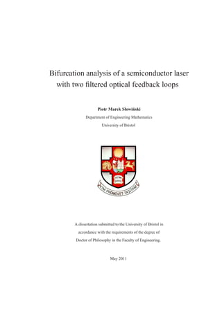
  • 35. 2.1. External filtered modes 13 . 0.3 Ω(ωs ) 0 −0.3 . −0.2 ωs −0.1 0 0.05 0.1 Figure 2.1. The graph of (2.3) (black curve) oscillates between its envelope (grey curve) given by (2.9). Frequencies of EFMs (blue dots) are found from intersection points of the graph of Ω(ωs ) with 1 the diagonal; also shown are the intersection points (black dots) with the envelope. Here Cp = 0, 2 Cp = π/3, ∆1 = −0.1, ∆2 = 0.05, κ1 = 0.05, κ2 = 0.025, Λ1 = Λ2 = 0.005, τ1 = 500 and τ2 = 400. sought frequency values ωs of the 2FOF laser can be determined from (2.2) numerically by root finding; for example, by Newton’s method in combination with numerical continuation. The two terms of the sum in the parentheses of (2.3) correspond to the first and the second filter, respectively. If one of the κi is set to zero, then (2.2) reduces to the transcendental equa- tion from [28] for the frequencies of EFMs of the single FOF laser. The advantage of the formulation of (2.2) is that it has a nice geometric interpretation: Ω(ωs ) is a function of ωs that 1 2 oscillates between two fixed envelopes. More precisely, when Cp or Cp are changed over 2π the graph of Ω(ωs ) sweeps out the area in between the envelopes. Figure 2.1 shows an example of the solutions of (2.2) as intersection points (blue dots) between the oscillatory function Ω(ωs ) and the diagonal (the straight line through the origin with slope 1); see also [74]. Once ωs is known, the corresponding values of the other state
  • 36. 14 Chapter 2. Classification of EFM structure variables of the EFMs can be found from   κ1 Λ1 cos(φ1 ) κ2 Λ2 cos(φ2 ) Ns = −  + , (2.5) Λ1 2 + (ωs − ∆1 )2 2 Λ2 + (ωs − ∆2 ) 2 P − Ns Es = , (2.6) 1 + 2Ns 1 Es Λ 1 Fs = , (2.7) Λ1 2 + (ωs − ∆1 )2 2 Es Λ 2 Fs = . (2.8) Λ2 2 + (ωs − ∆2 )2 This means that an EFM is, in fact, uniquely determined by its value of ωs . Furthermore, it is useful to consider the envelope of Ω(ωs ) (grey curves) so that Figure 2.1 represents all the rele- vant geometric information needed to determine and classify EFMs. Notice that in this specific example the EFMs are separated into three groups. The diagonal intersects the region bounded by the envelope in three disjoint intervals where frequencies ωs of EFMs may lie; these in- tervals correspond to three different EFM components as is discussed in section 2.1.1. As figure 2.1 suggests, EFMs are created and lost in saddle-node bifurcations when an extremum of the (black) graph passes through one of the boundary points (black dots) as a parameter (for 1 example, Cp ) is changed. This geometric picture is very similar to that for the single FOF laser [28], but there is an important difference. The envelope of Ω(ωs ) for the FOF laser is found by considering the extrema of the sine function (in (2.3) for, say, κ2 = 0). It turns out that the envelope for the single FOF laser is described by a polynomial of degree four, whose roots are the boundary points of at most two intervals (or components) with possible EFMs [28]. However, for the 2FOF laser, considering the extrema of the two sine functions in (2.3) is not sufficient since they appear in a sum. Hence, we also need to consider mixed terms resulting from the summation; with the use of standard trigonometric formulae, the equation for the envelope can
  • 37. 2.1. External filtered modes 15 be found as κ2 Λ2 1 1 κ2 Λ2 2 2 Ωe (ωs ) = ± 1 + α2 + 2 + Λ2 + (ωs − ∆1 )2 Λ2 + (ωs − ∆2 )2 1 2 1 ωs −∆2 ωs −∆1 1/2 2κ1 κ2 Λ1 Λ2 cos Cp − Cp + ωs (τ2 − τ1 ) + tan−1 Λ2 − tan−1 Λ1 . 2 2 Λ2 1 + (ωs − ∆1 ) Λ2 2 + (ωs − ∆2 ) (2.9) Indeed, when one of the κi is set to zero then (2.9) reduces to the fourth-order polynomial describing the envelope of the single FOF laser in [28]. However, for general values of the parameters, (2.9) is a transcendental equation, and not a polynomial of degree six as one might have hoped; nevertheless, by means of (2.9) the envelope Ωe (ωs ) can be plotted readily. The transcendental nature of (2.9) means that the study of the EFM structure of the 2FOF laser is a considerable challenge. As is shown here, the key is to find a suitable geometric viewpoint that allows one to understand the dependence of the EFMs on the different filter loop parameters. A first observation is that (2.9) depends on the differences 2 1 dCp := Cp − Cp and dτ := τ2 − τ1 , which we will hence consider as parameters in what follows; note that dCp is 2π-periodic as well. 2.1.1 EFM components It is well-known for the single FOF laser that its EFMs lie on closed curves in the (ωs , Ns )- plane. These curves are called EFM-components, and they arise as the set of all EFMs found for different values of feedback phase Cp , whilst the other parameters of the system are fixed. More specifically, when Cp is changed, EFMs are born in saddle-node bifurcations, then move over the respective EFM components in the direction of increasing ωs , and finally disappear again in saddle-node bifurcations. From an experimental point of view, EFM components are quite natural objects that can be measured as groups of EFMs whose frequencies vary with the feedback phase Cp ; see [19]. For the single FOF laser one finds either one or two EFM components, depending on the properties of the filter. Intuitively, one expects one EFM component centred around the solitary laser frequency and, if the detuning ∆ is large enough, a second EFM component around the filter central frequency. As was already mentioned, the exact dependence on the filter properties can be studied for the single FOF laser by considering the roots of a polynomial of degree four that arises from the equation for the envelope of the EFMs; see [28] for details.
  • 38. 16 Chapter 2. Classification of EFM structure For the 2FOF laser the situation is more complicated. Intuitively, one may think that now up to three EFM components may occur in the (ωs , Ns )-plane: one centred around the solitary laser frequency and two more around the central frequencies of the two filters. However, this intuition is not correct, and we will show that one may in fact have any number of EFM com- ponents. Physically, the reason for this vastly more complicated EFM structure of the 2FOF laser is the interference between the two filter fields, which can be interpreted as giving rise to a complicated ‘effective’ filter profile. Mathematically, the reason behind the more complicated EFM structure lies in the transcendental nature of the envelope equation (2.9). In spite of these underlying difficulties, we now proceed with providing a geometrical rep- resentation of the EFM structure of the 2FOF laser in dependence on system parameters. Since the transcendental EFM equation (2.2) is complicated and depends on all system parameters, its solutions can only be found numerically (except for certain very special choices of the pa- rameters). From the value of the EFM frequency ωs one can compute the values of the other 1 2 EFM quantities Es , Ns , Fs , Fs , φ1 and φ2 . In particular, the inversion Ns can be expressed as a function of ωs as κ2 Λ2 κ2 Λ2 Ns + (ωs − αNS )2 = 2 1 1 + 2 2 2 + Λ1 2 + (ωs − ∆1 )2 Λ2 + (ωs − ∆2 )2 ωs −∆2 ωs −∆1 2κ1 κ2 Λ1 Λ2 cos dCp + ωs dτ + tan−1 Λ2 − tan−1 Λ1 . Λ1 2 + (ωs − ∆1 )2 Λ2 2 + (ωs − ∆2 )2 (2.10) From this quadratic expression we can conclude that for any ωs there are either no, one or two solutions for Ns . In particular, any EFM component is a smooth closed curve that consists of two branches, one with a higher and one with a lower value of Ns , which connect at two points where (2.10) has exactly one solution. EFM components in the (ωs , Ns )-plane can be computed from the implicit transcendental equations (2.2) and (2.10) by root solving, ideally in combination with numerical continuation. An alternative approach is to find and then con- tinue in parameters EFMs directly as steady-state solutions of the governing system (1.1)–(1.4) of delay differential equations; this can be achieved with the numerical continuation package DDE-BIFTOOL [11]. Additionaly, by using DDE-BIFTOOL we can obtain stability informa- tion on the EFMs.
  • 39. 2.1. External filtered modes 17 2.1.2 EFM components for two identical filters The starting point of our study of the EFM structure is the special case that the two filters are 1 2 identical, apart from having differing feedback phases Cp and Cp . Hence, we now set κ := κ1 = κ2 , ∆ 1 = ∆2 , Λ := Λ1 = Λ2 , τ1 = τ 2 . The EFMs for this special case are given by the EFMs of a corresponding single FOF laser with effective feedback strength dCp κeff = 2κ cos (2.11) 2 and effective feedback phase eff 1 2 Cp = Cp + Cp /2. In other words, we obtain a non-trivial reduction of the 2FOF laser to the FOF laser, where the feedback phase difference dCp arises as a natural parameter that controls the effective feedback strength κeff as a result of interference between the two filter fields. One extreme case is that of constructive interference when dCp = 0 so that κeff = 2κ. The other extreme is the case of destructive interference when dCp = π and κeff = 0. Hence, by changing dCp we can ‘switch on’ or ‘switch off’ the overall filter field that the laser sees. 1 2 Clearly, which EFMs one finds depends on both feedback phases Cp and Cp . Branches 1 2 of EFMs are obtained by specifying a single condition on Cp and Cp , while keeping all other 1 2 parameters fixed. The easiest option is to continue EFM curves in, say, Cp while keeping Cp constant. Another option is to require that the frequency ωs remains fixed. Note that for the above choices the feedback phase difference dCp changes along the branch of EFMs. We now consider EFM components of the 2FOF, which we define as the branches of EFMs 1 2 that one finds when the feedback phases, Cp or Cp are changed while the feedback phase difference dCp is fixed. This definition is the appropriate generalisation from the single FOF laser [28]. The underlying idea is that the value of dCp determines the interference of the light from the two filtered feedback loops and, hence, an important property of the overall feedback the laser sees. In the simplest case of two identical feedback loops fixing dC p results in the fixed effective feedback strength κeff . However, as we will see, our notion of EFM components for the 2FOF laser is equally natural for nonidentical filter loops. Figure 2.2 shows a projection of different branches of EFMs onto the (ωs , Ns )-plane and 1 onto the (ωs , Cp )-plane, respectively. Here we fixed κ = κ1 = κ2 = 0.05, Λ := Λ1 = Λ2 = 0.015, τ1 = τ2 = 500, and consider the case where both filters are resonant with the
  • 40. 18 Chapter 2. Classification of EFM structure 5 . 0.02 (a) 1 Cp (b) Ns π 0 0 −0.02 −5 . −0.1 0 ωs 0.1 −0.1 0 ωs 0.1 1 Figure 2.2. Projection of EFMs branches onto the (ωs , Ns )-plane (a) and onto the (ωs , Cp )-plane (b). The open circles are the starting points for three different types of branches. The blue branch is the EFM 1 component for dCp = 0, the green branches are for constant Cp , and the red branches are for constant ωs . Here ∆1 = ∆2 = 0, κ1 = κ2 = 0.05, Λ1 = Λ2 = 0.015, dτ1 = τ2 = 500 and the other parameters are as given in Table 1.1. solitary laser, meaning that ∆1 = ∆2 = 0; the other parameters are as given in Table 1.1. Colour in figure 2.2 distinguishes three types of one-dimensional EFM branches; the three sets of blue, green and red curves are all clearly visible projection onto the (ωs , Ns )-plane in panel (a). The continuations were started from the set of EFMs (open circles) that one finds on the EFM component for dCp = 0 if one insists that one of the EFMs (the top open circle) has a frequency of ωs = 0. The outer blue curve in figure 2.2 (a) is a single EFM-component that connects all EFMs; it is indeed exactly the EFM component of the single FOF laser with a feedback strength of κeff = 1 2κ; see [28]. When Cp is increased by 2π, while keeping dCp = 0, each EFM moves along the blue EFM component to the position of its left neighbour. Hence, the EFM-component 1 can be calculated either by the continuation of all EFMs over the Cp -range of [0, 2π], or by the continuation of a single EFM over several multiples of 2π. The green curves are the branches of 2 1 EFMs that one obtains by changing Cp while keeping Cp constant. Notice that green branches connect an EFM at the top with one at the bottom of the blue EFM-component; the exception 2 is the branch near the origin of the (ωs , Ns )-plane, which connects three EFMs. When Cp is increased by 2π the respective EFMs on the green branch exchange their positions in a clockwise direction. Finally, the red branches in figure 2.2 (a) are the result of continuation of 1 2 EFM solutions for (1.1)–(1.4) in Cp and Cp while ωs is kept constant; hence, these branches appear as straight vertical lines that start at the respective EFM. Figure 2.2 (b) shows the exact 1 same branches but now in projection onto the (ωs , Cp )-plane. In this projection, the blue EFM 1 branch ‘unwraps’ as a single curve that oscillated in Cp ; this property is characteristic and can be found, more generally, for lasers with delayed feedback or coupling [28, 34, 61]. In the 1 (ωs , Cp )-plane the red and the green branches are perpendicular to each other. Furthermore, 1 the image is invariant under a 2π translation along the Cp -axis.
  • 41. 2.2. The EFM-surface 19 2.2 The EFM-surface The discussion in the previous section shows that the dependence of the EFMs on the feedback 1 2 phases Cp and Cp (when all other parameters are fixed) gives rise to different one-parameter families of EFM branches, depending on the conditions one poses. In other words, one is really dealing with a surface of EFMs in dependence on the two feedback phases, which is represented by any of the three families of EFM branches we discussed. Motivated by the question of how many EFM components there are for the 2FOF laser, and in line with the well-accepted representation of the external cavity mode structure for other laser systems with delay [34, 61], it is a natural choice to represent this surface by the EFM values of ωs and Ns in combination with one additional parameter. 1 A first and quite natural choice is to consider the EFM surface in the (ωs , Ns , Cp )-space. 1 This representation stresses the influence of an individual feedback phase, here Cp , which is convenient to make the connection with previous studies in [17, 35]. Figure 2.3 shows the EFM surface for the case of two identical filters in this way. Panel (a) shows a grey semitransparent two-dimensional object with EFMs branches from figure 2.2 superimposed. This object is the ‘basic’ element of the entire EFM surface, which consists of all infinitely many 2nπ-translated copies of this basic element. Note that the 2nπ-translated copies connect smoothly at the open ends of the surface element shown in panel (a). The element of the EFM surface was rendered from computed one-dimensional EFM branches for fixed ωs ; selection of these branches is shown as the red curves in figure 2.3 (a). Almost all red EFM branches are closed loops that connect two points, each on the blue branch. An exception is the central red EFM branch for ωs = 0, which connects infinitely many points on the infinitely long blue branch. Hence, this red branch is important for representing the EFM surface properly; it is defined by the conditions that both sine functions in (2.3) vanish, which means that 1 ∆1 Cp = π + tan−1 + tan−1 (α) , (2.12) Λ1 2 ∆2 Cp = π + tan−1 + tan−1 (α) . (2.13) Λ2 The starting points for the calculations of the red EFM branches are taken from the maximal blue curve, which corresponds to the maximal EFM component for dCp = 0; compare with 1 figure 2.2 (b). It forms the helix-like curve in (ωs , Ns , Cp )-space that is shown in figure 2.3 (a) 1 over one 2π interval of Cp . What is more, the shown part of the EFM surface is a fundamental 1 unit under the translational symmetry of Cp that contains all the information. This means that the entire EFM surface is obtained as a single smooth surface from all of the 2nπ-translated copies of the unit in figure 2.3 (a). Notice that the shown part of the EFM surface is tilted in the 1 Cp direction. More specifically, for negative ωs the red EFM branches are shifted toward higher
  • 42. 20 Chapter 2. Classification of EFM structure . 0.02 (a) Ns 0 0.1 ωs −0.02 0 15 1 Cp /π 0 −0.1 −15 (c) ωs 0 (b) Ns Ns 0 0 1 Cp /π ωs 1 Cp /π . 0 1 Figure 2.3. Representation of the EFM surface in (ωs , Ns , Cp )-space; compare with figure 2.2. Panel (a) shows one fundamental element of the EFM surface (semitransparent grey); superimposed are the EFM branches from figure 2.2. The entire EFM surface is a single smooth surface that is obtain by connecting all 2nπ-translated copies of the surface element shown in panel (a). Panels (b) and (c) show 1 how the EFM branches for constant Cp and for constant ωs , respectively, arise as intersection curves of fixed sections with the EFM surface. 1 1 values of Cp , whereas for positive ωs they are shifted toward lower values of Cp ; compare 1 with the projection onto the (ωs , Cp )-plane in figure 2.2 (b). Notice that for the maximal and minimal possible values of ωs , the red EFM branches contract to just single points on the blue EFMs branch. 1 The representation of the EFM surface in (ωs , Ns , Cp )-space in figure 2.3 is, in effect, the 1 three-dimensional analogue of the representation of the EFM branches in the (ωs , Cp )-plane 1 in figure 2.2 (b). In particular, the two sets of EFM branches for fixed Cp and fixed ωs (green