Recommendable # 971589162217 # philippine Young Call Girls in Dubai By Marina...
38620317 pro e-mechanism
1. 12-66
MECHANISM TUTORIAL
Within this tutorial, you will explore the assembly and animation capabilities of
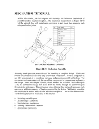
assembly mode’s mechanism option. The nutcracker model shown in Figure 12-92
will be utilized. You will model each component in part mode then assemble each
using mechanism joints.
Figure 12-92: Mechanism Assembly
Assembly mode provides powerful tools for modeling a complete design. Traditional
bottom-up constraints necessitate fully constrained components. When a component is
not fully constrained, it is considered packaged and presents assembly difficulties. The
mechanism option provides tools for assembling components in a manner that replicates a
real design. Joints such as pin, cylinder, slider, and ball are available. Notice in Figure
12-92 the connection linkage that exists from the handle through the connection part
through to the piston part. The mechanism joints defining these parts only constrain each
component within the degrees of freedom required by the design. Within this assembly,
the handle can be moved which in turn will move the piston. This will be demonstrated.
The following topics will be covered in this tutorial:
• Modeling assembly parts.
• Assembling a Mechanism.
• Manipulating a mechanism.
• Running a Mechanism’s Motion.
• Animating a mechanism.
3. 12-68
Modeling Assembly Parts
The assembly in this tutorial consists of eight different parts: base, cylinder, hinge,
piston, adjuster_base, adjuster, connection, and handle. There will be two instances of
the connection part. Use part mode to model each of the parts as shown in Figure 12-93.
When modeling each part, pay careful attention to the locations of your datum planes.
For proper assembly of the mechanism, your datum planes should match the datum
planes represented in each part’s drawing.
Assembling a Mechanism
Within this segment of the tutorial you will assembly the parts comprising the design.
Within this exercise, you will not use a template file. Do not start this segment of the
tutorial until you have modeled all the parts portrayed in Figure 12-93.
Step 1: Start Pro/ENGINEER and then select FILE >> NEW.
Step 2: On the New dialog box, deselect the USE DEFAULT TEMPLATE
OPTION.
Within this tutorial, do not use Pro/ENGINEER’s default template.
Step 3: Create a new Assembly object file named NUTCRACKER.ASM.
Step 4: On the New File Options dialog box, select the EMPTY template file
then select OK.
Step 5: Select COMPONENT >> ASSEMBLE on the Assembly menu.
Step 6: Using the Open dialog box, place the BASE part.
Without any existing features or components, Pro/ENGINEER will place
the first component without requiring any constraints or joints. If you
inadvertently created Pro/ENGINEER’s default datum planes, you can
mate and/or align the BASE part to these datum planes
Step 7: Select COMPONENT >> ASSEMBLE and open the CYLINDER part.
Step 8: Using traditional assembly constraints, assembly the Cylinder part as
shown in Figure 4-mech.
There are two ways to add components to a mechanism: Fixed and By
Connection. The Fixed option is identical to the traditional way of
assembling components in Pro/ENGINEER. The By Connection option
assembles components through joint definitions. It allows components to
4. 12-69
move based on the degrees of freedom provided by the selected joint. For
the cylinder part, assembly the component with one Mate constraint and
two Align constraints as shown in the illustration.
Figure 12-94: Cylinder Fixed Constraints
Figure 12-95: Adjuster_Base and Hinge Fixed Constraints
Step 9: When the Cylinder part is fully constrained, select OK to exit the
dialog box.
Step 10: Use the same technique for assembling the cylinder part to constrain
the HINGE and ADJUSTER_BASE parts (Figure 12-95).
As with the cylinder part, use two align constraints and one mate
constraint for each part. Your assembly should appear as shown in the
illustration.
Next you will assemble the Piston part using a Cylinder joint. Other
available joints include: Pin, Bearing, Slider, Planar, and Ball.
Step 11: Select ASSEMBLE then open the PISTON part.
5. 12-70
Step 12: On the Component Placement dialog box select CONNECTIONS
option.
Figure 12-96: Cylinder Joint Definition
Step 13: On the Component Placement dialog box, select CYLINDER as the
connection type (see Figure 12-96).
Step 14: Select the two axes shown in Figure 12-96.
A Cylinder joint type is defined through the alignment of two axes. This
joint type provides two degrees of freedom: one linear and one rotational.
Step 15: If necessary, select the FLIP option to point the piston’s cut feature
toward the hinge part (see Figure 12-96).
Step 16: On the dialog box, select the MOVE tab.
You will reposition the piston part to match Figure 8mech.
Figure 12-97: Move Option
Step 17: With the Translate and Entity/Edge options selected, pick the axis of
the piston part (see Figure 12-97).
Step 18: Move the Piston part’s location to approximately match Figure 12-97
then select the Place tab.
6. 12-71
After selecting the Place tab on the component placement dialog box,
notice the current placement status of the part. The placement status
should state “Connection Definition Complete”.
NOTE: You can also use the Mechanism >> Drag option to move
components that have mechanism joints.
Step 19: Select OK on the dialog box.
Figure 12-98: Adjuster Placement
Step 20: Use the ASSEMBLE option to open the ADJUSTER part.
Step 21: Use the same technique for assembling the piston part to constrain the
ADJUSTER part (Figure 12-98).
Use Cylinder as the connection for the component. If necessary, use the
Flip option and the Move tab to position the component to match the
illustration.
Figure 12-99: Handle Placement
Step 22: Use the ASSEMBLE option to open the HANDLE part.
Step 23: Select the PIN joint type under the Connections option (see Figure 12-
99).
Pin connections provide one rotational degree of freedom. It is defined
through the alignment of two axes and the aligning or mating of two
planes.
7. 12-72
Step 24: Align the hole axes of the handle and hinge parts as shown in Figure
12-99.
Step 25: With the Translation constraint type selected, mate one side of the
handle part with the end side surface of the hinge part.
Step 26: Use the Move tab to rotate the handle to the approximate location
shown in Figure 12-99.
Under the Move tab, use Rotate as the Motion Type and Entity/Edge as
the Motion Reference. The handle should be pointing toward the center of
the base part.
Step 27: Select OK to exit the dialog box.
Figure 12-100: Connection Part Placement
Step 28: Assemble the CONNECTION part.
Step 29: Create the PIN joint shown in Figure 11mech.
The connection part will have two joints: one pin and one cylinder. The
pin joint will join the connection part to the handle part. The cylinder
joint will join the connection part to the piston. If necessary, use the Flip
option to create the mate translation connection.
Step 30: Use the Move tab on the dialog box to rotate the connection part to
the approximate location shown in Figure 12-100.
8. 12-73
Step 31: Create the CYLINDER joint shown in Figure 11mech.
The Plus icon located under the connection names on the dialog is used to
add new joint types. After creating the cylinder joint, your assembly
connection will not look like the illustration. This is typical of a
Pro/ENGINEER looped mechanism. In a later step, you will execute the
Connect option to assume a successful assembly.
Step 32: If the placement status signifies a complete connection, select OK to
exit the dialog box.
Step 33: Use the same technique for assembling the first connection part to
place the second instance of the connection part.
Repeat Steps 28 through 32 to place the second instance of the connection
part.
Step 34: Select DONE/RETURN to exit the Component menu.
Step 35: Select MECHANISM >> CONNECT >> RUN to connect the loop
assembly.
Instructional Point
If you do not get a successful assembly after selecting the Run option, use the
Mechanism >> Settings option to adjust the tolerance of the assembly (see Figure 12-
101).
Figure 12-101: Assembly Setting
Step 36: If you get a positive confirmation message, select YES to accept the
successful assembly.
Step 37: Save the assembly.
Manipulating a Mechanism
This segment of the tutorial will demonstrate how components can be dragged through
any defined degrees of freedom. In addition, you will create snapshots of component
placements that will be used in the last segment of this tutorial to animate the mechanism.
9. 12-74
Figure 12-102: Drag Entity Selection
Step 1: Select the DRAG option from under the Mechanism menu.
Step 2: On the Drag dialog box, select the Point Drag icon (Figure 12-102)
then select the end of the handle part (see Figure 12-103).
The Drag dialog box is used to drag components on the screen. Use the
Point option to select the end of the handle part. After selecting the
handle, you can dynamically drag the component with the mouse. Use the
Left-Mouse button to end dragging.
Figure 12-103: Drag Positions
Step 3: Drag the handle to the First Position shown in Figure 12-103.
10. 12-75
Figure 12-103 represents a side view of the assembly. You can utilize any
orientation to include a user-defined viewpoint.
Step 4: On the Drag dialog box, select the SNAPSHOT icon (Figure 12-102).
Snapshots can be used to restore a mechanism’s position and to created
animations. You will use the snapshots created in this segment to animate
the mechanism in the last segment of this tutorial.
Step 5: Drag the handle to the second position shown in Figure 12-103 then
create a second snapshot.
Step 6: Close the Drag dialog box.
Running a Mechanism’s Motion
Motion, as defined by the degrees of freedom within a mechanism, can be animated.
Within this segment of the tutorial, you will define the motion of the assembly through
the use of a driver.
Figure 12-104: Driver Creation
Step 1: Select the MODEL >> DRIVERS option on the Mechanism menu.
Step 2: On the Drivers dialog box, select the ADD option (Figure 12-104).
11. 12-76
Step 3: For the Driven Entity, select the pick icon, then on the work
screen pick the pin joint shown in Figure 12-104.
Step 4: If available, on the Driver Editor dialog box, select ROTATION as the
Motion Type (Figure 12-104).
Step 5: Select the Profile tab then select VELOCITY as the specification
(Figure 12-105).
Step 6: Change the Magnitude option to COSINE then enter the values
shown in Figure 12-105.
Step 7: Select the GRAPH option to observe the graph of your mechanism.
Step 8: Close the Graph windows.
Figure 12-105: Driver Editor Dialog Box
12. 12-77
Figure 12-106: Zero Reference Selection
Step 9: Select the SET ZERO option on the dialog box then set the CYAN
BODY REFERENCE and the GREEN BODY REFERENE as shown
in Figure 12-106.
This will define the starting point for the mechanism animation.
Step 10: Select OK to exit the Joint Axis Settings dialog box.
Step 11: On the Driver Editor dialog box, enter 10.00 as the Initial Angle for
the driver (Figure 12-107).
This setting will establish an initial position for the mechanism 10 degrees
from the set zero position.
Instructional Point
Notice on the work screen the arrow representing the joint’s joint. Using the right-
hand rule with your thumb pointing in the direction of the arrow, your fingers will
point in the direction of driver rotation. If necessary, you might have to enter a
negative 10.00 value for the initial angle.
Figure 12-107: Initial Angle Setting
Step 12: Select OK to exit the Driver Editor dialog box.
Step 13: Close the Drivers dialog box.
Step 14: Select the RUN MOTION option under the Mechanism menu.
13. 12-78
After selecting the Run Motion option, Pro/ENGINEER will launch the
Motion Definitions dialog box. This dialog box is used to establish
multiple motion definitions for a mechanism.
Step 15: Select the ADD option on the Motion Definition dialog box.
Figure 12-108: Motion Definition
Dialog Box
Step 16: Select OK to accept the default settings on the Motion Definition
dialog box (Figure 12-108).
Step 17: Select RUN on the Motion Definitions dialog box.
With any luck, after selecting the Run option, your mechanism should
animate based on defined degrees of freedom and the set driver. If you
have unexpected results in your animate, try adjusting the driver’s profile
values or the driver’s initial angle value.
Step 18: Close the Motion Definitions dialog box.
Step 19: Select RESULTS >> PLAYBACK on the Mechanism menu
Step 20: Select the PLAY option on the Results Playback dialog box.
Step 21: Use options on the Animate dialog box to run the results of your
motion study (Figure 12-109).
Step 22: Close out of the Mechanism option and save your assembly.
14. 12-79
Figure 12-109: Animate Dialog Box
Animating a Mechanism
Mechanisms can be animated using Pro/ENGINEER’s Animation mode. Within this
segment of the tutorial, you will use the snapshots created previously to animate the
nutcracker assembly.
Step 1: Using Pro/ENGINEER’s Menu Bar, select APPLICATIONS >>
ANIMATION.
Upon selecting the Animation option, Pro/ENGINEER will reveal the
Animation toolbar (Figure 12-110) and, at the bottom of the screen, a
timeline.
Figure 12-110: Animation Dialog box
Step 2: Select the ANIMATION icon on the toolbar then select the NEW
icon to create a new animation.
Step 3: Close the Animation dialog box.
15. 12-80
Step 4: Double pick the timeline at the bottom of the work screen and set the
time domain values shown in Figure 12-111.
Step 5: Select OK to create the time domain.
Step 6: Select the NEW KEY FRAME SEQUENCE icon.
Multiple key frame sequences can be created for an animation. Within
this tutorial, two will be used. The first sequence will utilize the two
snapshots created previously to animate the handle and piston linkage.
The second sequence will animate the adjuster.
Figure 12-111: Time Domain
Step 7: On the dialog box, use the ADD KEY FRAME icon to create the
three key frames shown on the Key Frame Sequence dialog box
(Figure 12-112).
Two snapshots should currently exist. Use the Add Key Frame icon to
create the three key frames shown in Figure 25 (snapshot1 at 0 sec,
snapshot2 at 10 sec, and snapshot1 at 20 second). To perform this, select
an existing snapshot, set a specific time value, and then select the Add
Key Frame icon.
Step 8: Select OK when your Key Frame Sequence dialog box matches Figure
12-112.
Step 9: Select the START icon on the Animation toolbar (Figure 12-111).
Your handle and piston linkage should animate.
16. 12-81
Step 10: Select the NEW KEY FRAME SEQUENCE icon.
The next key frame sequence will animate the adjuster part.
Figure 12-112: Key Frame Sequence Dialog Box
Step 11: Select the NEW SNAPSHOT icon on the Key Frame Sequence
dialog box.
The New Snapshot icon will launch the Drag dialog box (Figure 12-113).
This dialog box is also accessible directly from the Animation dialog box.
Step 12: Select the POINT DRAG icon then drag the adjuster part to the
SNAPSHOT4 position shown in Figure 12-113.
Your snapshot numbers may be different from those represented in this
tutorial. You can approximate the exact location for each shot.
17. 12-82
Figure 12-113: Snapshot Creation
Step 13: Select the SNAPSHOT icon to create snapshot4.
Step 14: Select the POINT DRAG icon then drag the adjuster part to the
SNAPSHOT5 position shown in Figure 12-113.
Step 15: Select the SNAPSHOT icon to create snapshot5 then close the
Drag dialog box.
Step 16: Modify Snapshot5 (see Figure 12-114) to have a value of 10 seconds.
Step 17: Select OK to close the Key Frame Sequence dialog box.
Key Frame Sequences can be modified with the Animation >> Key Frame
Sequence option on Pro/ENGINEER’s menu bar. Your timeline should
look similar to Figure 12-115. Key frames on the timeline are represented
by the triangle symbol. They can be manipulated on the timeline by
dragging with the mouse.
Step 18: Use your mouse to drag the second key frame sequence to the position
shown in Figure 12-115.
18. 12-83
Figure 12-114: Key Frame Sequence
Dialog box
Figure 12-115: Animation Timeline
Step 19: Run the animation by selecting the START icon on the
Animation toolbar.
Step 20: Playback the created animation by selecting the Playback icon.
Step 21: Save your assembly file.