SlideShare une entreprise Scribd logo
1  sur  5
Télécharger pour lire hors ligne
Chap 5. Analog Transmission           1


                                5. Analog Transmission
 1.   Define analog transmission.
      Analog transmission refers to the transmission of analog signals using a band-pass channel. Baseband
      digital or analog signals are converted to a complex analog signal with a range of frequencies suitable
      for the channel.

 2.   Define carrier signal and its role in analog transmission.
      1. In analog transmission, the sending device produces a high-frequency signal that acts as a base for
         the information signal. This base signal is called the carrier signal or carrier frequency. It is a
         constant frequency signal.
      2. The carrier frequency is chosen so that it is compatible with the transmission medium.
      3. The receiving device must be tuned into the frequency of this carrier signal.
      4. Digital information changes one or more characteristics of the carrier signal (e.g., amplitude,
         frequency, or phase). This digital information is the input signal or modulating signal.
      5. This type of modification is called modulation or shift keying. The resultant signal is called a
         modulated signal.

 3.   Define digital-to-analog conversion.
      1. An analog signal has characteristics such as frequency, amplitude and phase.
      2. The process of changing one of the characteristics of an analog signal based on the information in
         digital data is called digital-to-analog conversion. It is also called modulation of a digital signal.
      3. When we change any one of the characteristics of a sine wave, we create a new wave.
      4. We can change any one characteristics of an analog signal so as to represent digital data.
      5. Thus, there are following three methods to modulate digital data into analog data. These techniques
         are: frequency shift keying (FSK), amplitude shift keying. (ASK), and phase shift keying (PSK).
      6. A fourth technique is called QAM (quadrature amplitude modulation) and it combines changes in
         both amplitude and phase. This is the most efficient method of converting digital signal to analog.
      7. At the transmitting end, the conversion of digital to analog data is done by the modulator, while at
         the receiving end conversion of analog signal back to digital data is carried out by the demodulator.

 4.   Describe amplitude shift keying (ASK).
      1. In amplitude shift keying (ASK), the amplitude of the carrier wave is changed but frequency and
         phase remain constant.
      2. The two types of techniques are: Binary ASK (BASK) and Multilevel ASK (MASK).
      3. Binary ASK: In binary ASK, we have 2 types of signal elements. Each signal element has different
         amplitude.


      4. Bandwidth for ASK: When a simple sine wave is modulated, it produces a non-periodic composite
          signal. This signal has a continuous range of frequencies. The bandwidth is proportional to the
          signal rate. The bandwidth is also dependent on another factor d which depends on the modulation
          and filtering. ) and 0 <= d <= 1.

                         B = (1 + d) x S, where S is the signal rate and B is the bandwidth.

mukeshtekwani@hotmail.com                                                        Prof. Mukesh N. Tekwani
2    Analog Transmission


          Minimum bandwidth is obtained when d = 0 or B = S and maximum bandwidth is obtained when d = 1
          and B = 2S.

          5. From the diagram we observe that the middle of the bandwidth coincides with the carrier frequency
              fc. So if we have a bandpass channel available we can choose fc so that the modulated signal
              occupies the bandwidth.


          6. Consider a digital signal with a high voltage of 1V and a low voltage of 0 V. We multiply the
              digital signal by the carrier signal. When the amplitude of the digital signal is 1, the amplitude of
              the carrier frequency is max and when the amplitude of the digital signal becomes 0, the amplitude
              of the carrier signal is also 0.

          7. In full-duplex transmission, data has to be sent in
              both directions. The available bandwidth is
              divided into two with 2 carrier frequencies. The
              total bandwidth of 100 kHz is divided into 2 parts
              of 50 kHz each. The available bandwidth for
              each direction is now 50 kHz.

          Multilevel ASK:
          In multilevel ASK, there are more than 2 levels of the digital signal. We can use 4, 8, 16 or more
          different amplitudes for the signal and modulate the data using 2, 3, 4 or more bits at a time.

     5.   Describe frequency shift keying (FSK).
          1. In FSK, the frequency of the carrier is
             changed to represent the binary 1 and 0.
             For binary 0 the carrier frequency will be
             f1 and for binary 1, the frequency will be
             f 2.
          2. The frequency of the modulated signal is
             constant for the duration of one signal
             element (say binary 0) but changes for
             the next signal element (say binary 1).
          3. The peak amplitude and phase remain constant.
          4. Bandwidth for FSK: The middle of one bandwidth is f1 while
             the middle of the other bandwidth is f2. These two bandwidths
             are Δf apart from the midpoint between the two bands. The
             difference between the two frequencies is 2 Δf.

          Multilevel FSK: This is also called multiple FSK. More than 2
          frequencies are used. E.g., we can use 4 different frequencies to
          send 2 bits at a time. To send 3 bits at a time, we use 8 frequencies.


    Prof. Mukesh N Tekwani                                                         mukeshtekwani@hotmail.com
Chap 5: Analog Transmission          3


 6.   Describe phase shift keying (PSK).
      In phase shift keying, the phase of the carrier is changed to represent different signal elements (1 / 0).
      The peak amplitude and frequency remain constant.

      Binary PSK:
      1. There are only 2 signal elements one with a phase shift of 0o ; the other with a phase shift of 180 o.


      2. The advantage of PSK is that it is less susceptible (or affected) by noise. In PSK, the bit detection
         depends on the phase of the carrier signal. Although noise can change the amplitude of the carrier,
         changes in phase are more difficult. Also, PSK is superior to FSK because we donot require 2
         carrier signals.
      3. Implementing FSK is simple because the signal element with phase 180o is just the complement of
         the signal element with phase 0. We multiply a polar NRZ data signal with a carrier signal. We
         represent the 1 bit (positive voltage) by phase starting at 0 . The 0 bit (negative voltage) is
         represented by a phase starting at 1800

      Quadrature PSK:
      1. Instead of using only 2 variations of a signal, we use four variations.
      2. Each phase shift represents 2 bits. A phase of 00 now represents 00; 900 represents 01; 1800
         represents 10; and 2700 represents 11. This technique is called 4-PSK or Q-PSK. The pair of bits
         represented by each phase is called a dibit.
      3. The incoming bits are first passed through a serial to parallel converter. It sends one bit to a
         modulator and the next bit to another modulator.


      4. The 2 signals created by multipliers are sine waves with same frequency but different phases.
          When these two signals are added, the result is another sine wave which can have phases of 45o, -
          45o, 135o, or -135o. Since there are four kinds of signal elements in the output signal, we can send
          2 bits per signal element.

mukeshtekwani@hotmail.com                                                           Prof. Mukesh N. Tekwani
4    Analog Transmission


     7.   Describe Quadrature Amplitude Modulation (QAM).
          1. This modulation technique is a combination of ASK and PSK.
          2. In QAM technique, we change two characteristics – the amplitude of one carrier wave and the and
             the phase of the other carrier wave.
          3. The amplitude of the two carrier signals are different.

     8.   Define analog-to-analog conversion.
          1. Analog-to-analog conversion I the representation of analog information by an analog signal.
          2. Such a modulation is required if the medium is bandpass.
          3. Analog-to-analog conversion is achieved in 3 ways: Amplitude Modulation (AM), Frequency
             Modulation (FM), and Phase Modulation (PM)

     9.   Describe Amplitude Modulation (AM)
          1. Modulation is defined as the process of combining an input signal and a carrier frequency to
             produce a signal whose bandwidth is centered around fc.
          2. In AM, we use two signals: the carrier signal and the modulating signal. Both are analog signals.
          3. The carrier signal is modulated so that its amplitude varies with changes in the amplitude of the
             modulating signal.
          4. The frequency and phase of the carrier signal remain constant, only the amplitude changes.


          5. The modulating signal is the envelope of the carrier wave.
          6. The bandwidth of the AM signal is two times the bandwidth of the modulating signal. The central
             frequency is fc. The signal components above and below fc carry the same information.

          Why is modulation of analog signal necessary?
          Modulation of an analog signal is necessary for two reasons:
          a) A higher frequency may be needed for transmission of a signal. The size of the antenna decreases
             as the carrier frequency increases so a modulated signal is needed.
          b) Modulation permits frequency division multiplexing.

    10.   Describe Frequency Modulation (FM)
          1. In Frequency Modulation, the frequency of the carrier wave is changed to follow the changing
             amplitude of the modulating signal.
          2. The peak amplitude and phase of the carrier signal remain constant but as the amplitude of the
             modulating (or information) signal changes, the frequency o the carrier signal also changes.
          3. The total bandwidth of the FM signal is given by: BW = 2(1 + β)B, where β is the modulation
             index


    Prof. Mukesh N Tekwani                                                 mukeshtekwani@hotmail.com
Chap 5: Analog Transmission           5


11.   Discuss Phase Modulation (PM).
      1. In Phase Modulation, the phase of the carrier signal is changed in accordance with the changing
          amplitude of the modulating signal.
      2. The peak amplitude and frequency of the carrier signal remain constant, but the phase of the carrier
          changes with changes in amplitude of the information signal (or the modulating signal).


mukeshtekwani@hotmail.com                                                       Prof. Mukesh N. Tekwani

Contenu connexe

Tendances

Multiplexing
MultiplexingMultiplexing
Multiplexingnimay1
 
TDMA, FDMA, and CDMA
TDMA, FDMA, and CDMATDMA, FDMA, and CDMA
TDMA, FDMA, and CDMANajeeb Khan
 
Basics of analog communication system
Basics of analog communication systemBasics of analog communication system
Basics of analog communication systemswatihalunde
 
Chapter 3 - Data and Signals
Chapter 3 - Data and SignalsChapter 3 - Data and Signals
Chapter 3 - Data and SignalsWayne Jones Jnr
 
Transmission impairments(presentation)
Transmission impairments(presentation)Transmission impairments(presentation)
Transmission impairments(presentation)Vivek Kumar
 
Multiplexing, fdma,tdma,cdma
Multiplexing, fdma,tdma,cdmaMultiplexing, fdma,tdma,cdma
Multiplexing, fdma,tdma,cdmanimay1
 
Data Communication And Networking - DATA RATE LIMITS
Data Communication And Networking - DATA RATE LIMITSData Communication And Networking - DATA RATE LIMITS
Data Communication And Networking - DATA RATE LIMITSAvijeet Negel
 
Cellular network
Cellular networkCellular network
Cellular networkshreb
 
Multiplexing in mobile computing
Multiplexing in mobile computingMultiplexing in mobile computing
Multiplexing in mobile computingZituSahu
 
Asynchronous transfer mode
Asynchronous transfer modeAsynchronous transfer mode
Asynchronous transfer modeaniston0108
 
Transmission media
Transmission mediaTransmission media
Transmission mediakinish kumar
 
3.2 modulation formats bpsk, qpsk, oqpsk,
3.2 modulation formats   bpsk, qpsk, oqpsk,3.2 modulation formats   bpsk, qpsk, oqpsk,
3.2 modulation formats bpsk, qpsk, oqpsk,JAIGANESH SEKAR
 
OFDM (Orthogonal Frequency Division Multiplexing )
OFDM (Orthogonal Frequency Division Multiplexing �)OFDM (Orthogonal Frequency Division Multiplexing �)
OFDM (Orthogonal Frequency Division Multiplexing )Juan Camilo Sacanamboy
 
RANDOM ACCESS PROTOCOL IN COMMUNICATION
RANDOM ACCESS PROTOCOL IN COMMUNICATION           RANDOM ACCESS PROTOCOL IN COMMUNICATION
RANDOM ACCESS PROTOCOL IN COMMUNICATION AMOGHA A K
 

Tendances (20)

Multiplexing
MultiplexingMultiplexing
Multiplexing
 
TDMA, FDMA, and CDMA
TDMA, FDMA, and CDMATDMA, FDMA, and CDMA
TDMA, FDMA, and CDMA
 
Basics of analog communication system
Basics of analog communication systemBasics of analog communication system
Basics of analog communication system
 
Ch 03
Ch 03Ch 03
Ch 03
 
Ch 05
Ch 05Ch 05
Ch 05
 
Chapter 3 - Data and Signals
Chapter 3 - Data and SignalsChapter 3 - Data and Signals
Chapter 3 - Data and Signals
 
Chapter 5
Chapter 5Chapter 5
Chapter 5
 
Transmission impairments(presentation)
Transmission impairments(presentation)Transmission impairments(presentation)
Transmission impairments(presentation)
 
Multiplexing, fdma,tdma,cdma
Multiplexing, fdma,tdma,cdmaMultiplexing, fdma,tdma,cdma
Multiplexing, fdma,tdma,cdma
 
Equalization
EqualizationEqualization
Equalization
 
Data Communication And Networking - DATA RATE LIMITS
Data Communication And Networking - DATA RATE LIMITSData Communication And Networking - DATA RATE LIMITS
Data Communication And Networking - DATA RATE LIMITS
 
Cellular network
Cellular networkCellular network
Cellular network
 
Multiplexing in mobile computing
Multiplexing in mobile computingMultiplexing in mobile computing
Multiplexing in mobile computing
 
Asynchronous transfer mode
Asynchronous transfer modeAsynchronous transfer mode
Asynchronous transfer mode
 
Transmission media
Transmission mediaTransmission media
Transmission media
 
Medium access control unit 3-33
Medium access control  unit 3-33Medium access control  unit 3-33
Medium access control unit 3-33
 
3.2 modulation formats bpsk, qpsk, oqpsk,
3.2 modulation formats   bpsk, qpsk, oqpsk,3.2 modulation formats   bpsk, qpsk, oqpsk,
3.2 modulation formats bpsk, qpsk, oqpsk,
 
OFDM (Orthogonal Frequency Division Multiplexing )
OFDM (Orthogonal Frequency Division Multiplexing �)OFDM (Orthogonal Frequency Division Multiplexing �)
OFDM (Orthogonal Frequency Division Multiplexing )
 
RANDOM ACCESS PROTOCOL IN COMMUNICATION
RANDOM ACCESS PROTOCOL IN COMMUNICATION           RANDOM ACCESS PROTOCOL IN COMMUNICATION
RANDOM ACCESS PROTOCOL IN COMMUNICATION
 
CDMA
CDMACDMA
CDMA
 

En vedette (20)

Data communication and network Chapter - 2
Data communication and network Chapter - 2Data communication and network Chapter - 2
Data communication and network Chapter - 2
 
Ch10
Ch10Ch10
Ch10
 
Chapter 26 - Remote Logging, Electronic Mail & File Transfer
Chapter 26 - Remote Logging, Electronic Mail & File TransferChapter 26 - Remote Logging, Electronic Mail & File Transfer
Chapter 26 - Remote Logging, Electronic Mail & File Transfer
 
Data communications
Data communicationsData communications
Data communications
 
Digital data transmission,line coding and pulse shaping
Digital data transmission,line coding and pulse shapingDigital data transmission,line coding and pulse shaping
Digital data transmission,line coding and pulse shaping
 
Ch06
Ch06Ch06
Ch06
 
Ch18
Ch18Ch18
Ch18
 
Chap5 analog transmission
Chap5 analog transmissionChap5 analog transmission
Chap5 analog transmission
 
Data transmission
Data transmissionData transmission
Data transmission
 
Serial transmission
Serial transmissionSerial transmission
Serial transmission
 
Secure Data Transmission
Secure Data TransmissionSecure Data Transmission
Secure Data Transmission
 
Ch25
Ch25Ch25
Ch25
 
Analog Transmission
Analog TransmissionAnalog Transmission
Analog Transmission
 
Analog Transmission
Analog TransmissionAnalog Transmission
Analog Transmission
 
Digital & analog transmission
Digital & analog transmissionDigital & analog transmission
Digital & analog transmission
 
2[1].1 data transmission
2[1].1 data transmission2[1].1 data transmission
2[1].1 data transmission
 
Ch15
Ch15Ch15
Ch15
 
Ch31
Ch31Ch31
Ch31
 
Ch08
Ch08Ch08
Ch08
 
Ch21
Ch21Ch21
Ch21
 

Similaire à Analog Transmission Techniques

Similaire à Analog Transmission Techniques (20)

ASK,FSK and M-PSK using Matlab
ASK,FSK and M-PSK using MatlabASK,FSK and M-PSK using Matlab
ASK,FSK and M-PSK using Matlab
 
Lecture 11
Lecture 11Lecture 11
Lecture 11
 
dspppt.pptx
dspppt.pptxdspppt.pptx
dspppt.pptx
 
DCN 5th ed. slides ch05 Analog Transmission.pdf
DCN 5th ed. slides ch05 Analog Transmission.pdfDCN 5th ed. slides ch05 Analog Transmission.pdf
DCN 5th ed. slides ch05 Analog Transmission.pdf
 
05 analog transmission
05 analog transmission05 analog transmission
05 analog transmission
 
Digital To Analog Conversion
Digital To Analog ConversionDigital To Analog Conversion
Digital To Analog Conversion
 
Rf fundamentals
Rf fundamentalsRf fundamentals
Rf fundamentals
 
Lecture8 digitaltoanalogconversion
Lecture8 digitaltoanalogconversionLecture8 digitaltoanalogconversion
Lecture8 digitaltoanalogconversion
 
Linear modulation
Linear modulation Linear modulation
Linear modulation
 
Mod1
Mod1Mod1
Mod1
 
Mod1
Mod1Mod1
Mod1
 
Ch4 linear modulation pg 111
Ch4 linear modulation pg 111Ch4 linear modulation pg 111
Ch4 linear modulation pg 111
 
ADC Unit 1.pdf
ADC Unit 1.pdfADC Unit 1.pdf
ADC Unit 1.pdf
 
Modulation of digital_and_analog_data
Modulation of digital_and_analog_dataModulation of digital_and_analog_data
Modulation of digital_and_analog_data
 
Digital modulation technique
Digital modulation techniqueDigital modulation technique
Digital modulation technique
 
Networking notes part2 final
Networking notes part2 finalNetworking notes part2 final
Networking notes part2 final
 
mod.pptx
mod.pptxmod.pptx
mod.pptx
 
Communication system lec 8
Communication system lec 8Communication system lec 8
Communication system lec 8
 
UNIT-4 Baseband Digital Modulation.pdf
UNIT-4 Baseband Digital Modulation.pdfUNIT-4 Baseband Digital Modulation.pdf
UNIT-4 Baseband Digital Modulation.pdf
 
Data Encoding
Data EncodingData Encoding
Data Encoding
 

Plus de Mukesh Tekwani

ISCE-Class 12-Question Bank - Electrostatics - Physics
ISCE-Class 12-Question Bank - Electrostatics  -  PhysicsISCE-Class 12-Question Bank - Electrostatics  -  Physics
ISCE-Class 12-Question Bank - Electrostatics - PhysicsMukesh Tekwani
 
Hexadecimal to binary conversion
Hexadecimal to binary conversion Hexadecimal to binary conversion
Hexadecimal to binary conversion Mukesh Tekwani
 
Hexadecimal to decimal conversion
Hexadecimal to decimal conversion Hexadecimal to decimal conversion
Hexadecimal to decimal conversion Mukesh Tekwani
 
Hexadecimal to octal conversion
Hexadecimal to octal conversionHexadecimal to octal conversion
Hexadecimal to octal conversionMukesh Tekwani
 
Gray code to binary conversion
Gray code to binary conversion Gray code to binary conversion
Gray code to binary conversion Mukesh Tekwani
 
Decimal to Binary conversion
Decimal to Binary conversionDecimal to Binary conversion
Decimal to Binary conversionMukesh Tekwani
 
Video Lectures for IGCSE Physics 2020-21
Video Lectures for IGCSE Physics 2020-21Video Lectures for IGCSE Physics 2020-21
Video Lectures for IGCSE Physics 2020-21Mukesh Tekwani
 
Refraction and dispersion of light through a prism
Refraction and dispersion of light through a prismRefraction and dispersion of light through a prism
Refraction and dispersion of light through a prismMukesh Tekwani
 
Refraction of light at a plane surface
Refraction of light at a plane surfaceRefraction of light at a plane surface
Refraction of light at a plane surfaceMukesh Tekwani
 
Atom, origin of spectra Bohr's theory of hydrogen atom
Atom, origin of spectra Bohr's theory of hydrogen atomAtom, origin of spectra Bohr's theory of hydrogen atom
Atom, origin of spectra Bohr's theory of hydrogen atomMukesh Tekwani
 
Refraction of light at spherical surfaces of lenses
Refraction of light at spherical surfaces of lensesRefraction of light at spherical surfaces of lenses
Refraction of light at spherical surfaces of lensesMukesh Tekwani
 
ISCE (XII) - PHYSICS BOARD EXAM FEB 2020 - WEIGHTAGE
ISCE (XII) - PHYSICS BOARD EXAM FEB 2020 - WEIGHTAGEISCE (XII) - PHYSICS BOARD EXAM FEB 2020 - WEIGHTAGE
ISCE (XII) - PHYSICS BOARD EXAM FEB 2020 - WEIGHTAGEMukesh Tekwani
 
TCP-IP Reference Model
TCP-IP Reference ModelTCP-IP Reference Model
TCP-IP Reference ModelMukesh Tekwani
 

Plus de Mukesh Tekwani (20)

Circular motion
Circular motionCircular motion
Circular motion
 
Gravitation
GravitationGravitation
Gravitation
 
ISCE-Class 12-Question Bank - Electrostatics - Physics
ISCE-Class 12-Question Bank - Electrostatics  -  PhysicsISCE-Class 12-Question Bank - Electrostatics  -  Physics
ISCE-Class 12-Question Bank - Electrostatics - Physics
 
Hexadecimal to binary conversion
Hexadecimal to binary conversion Hexadecimal to binary conversion
Hexadecimal to binary conversion
 
Hexadecimal to decimal conversion
Hexadecimal to decimal conversion Hexadecimal to decimal conversion
Hexadecimal to decimal conversion
 
Hexadecimal to octal conversion
Hexadecimal to octal conversionHexadecimal to octal conversion
Hexadecimal to octal conversion
 
Gray code to binary conversion
Gray code to binary conversion Gray code to binary conversion
Gray code to binary conversion
 
What is Gray Code?
What is Gray Code? What is Gray Code?
What is Gray Code?
 
Decimal to Binary conversion
Decimal to Binary conversionDecimal to Binary conversion
Decimal to Binary conversion
 
Video Lectures for IGCSE Physics 2020-21
Video Lectures for IGCSE Physics 2020-21Video Lectures for IGCSE Physics 2020-21
Video Lectures for IGCSE Physics 2020-21
 
Refraction and dispersion of light through a prism
Refraction and dispersion of light through a prismRefraction and dispersion of light through a prism
Refraction and dispersion of light through a prism
 
Refraction of light at a plane surface
Refraction of light at a plane surfaceRefraction of light at a plane surface
Refraction of light at a plane surface
 
Spherical mirrors
Spherical mirrorsSpherical mirrors
Spherical mirrors
 
Atom, origin of spectra Bohr's theory of hydrogen atom
Atom, origin of spectra Bohr's theory of hydrogen atomAtom, origin of spectra Bohr's theory of hydrogen atom
Atom, origin of spectra Bohr's theory of hydrogen atom
 
Refraction of light at spherical surfaces of lenses
Refraction of light at spherical surfaces of lensesRefraction of light at spherical surfaces of lenses
Refraction of light at spherical surfaces of lenses
 
ISCE (XII) - PHYSICS BOARD EXAM FEB 2020 - WEIGHTAGE
ISCE (XII) - PHYSICS BOARD EXAM FEB 2020 - WEIGHTAGEISCE (XII) - PHYSICS BOARD EXAM FEB 2020 - WEIGHTAGE
ISCE (XII) - PHYSICS BOARD EXAM FEB 2020 - WEIGHTAGE
 
Cyber Laws
Cyber LawsCyber Laws
Cyber Laws
 
XML
XMLXML
XML
 
Social media
Social mediaSocial media
Social media
 
TCP-IP Reference Model
TCP-IP Reference ModelTCP-IP Reference Model
TCP-IP Reference Model
 

Dernier

Bun (KitWorks Team Study 노별마루 발표 2024.4.22)
Bun (KitWorks Team Study 노별마루 발표 2024.4.22)Bun (KitWorks Team Study 노별마루 발표 2024.4.22)
Bun (KitWorks Team Study 노별마루 발표 2024.4.22)Wonjun Hwang
 
Designing IA for AI - Information Architecture Conference 2024
Designing IA for AI - Information Architecture Conference 2024Designing IA for AI - Information Architecture Conference 2024
Designing IA for AI - Information Architecture Conference 2024Enterprise Knowledge
 
Leverage Zilliz Serverless - Up to 50X Saving for Your Vector Storage Cost
Leverage Zilliz Serverless - Up to 50X Saving for Your Vector Storage CostLeverage Zilliz Serverless - Up to 50X Saving for Your Vector Storage Cost
Leverage Zilliz Serverless - Up to 50X Saving for Your Vector Storage CostZilliz
 
Unraveling Multimodality with Large Language Models.pdf
Unraveling Multimodality with Large Language Models.pdfUnraveling Multimodality with Large Language Models.pdf
Unraveling Multimodality with Large Language Models.pdfAlex Barbosa Coqueiro
 
"Subclassing and Composition – A Pythonic Tour of Trade-Offs", Hynek Schlawack
"Subclassing and Composition – A Pythonic Tour of Trade-Offs", Hynek Schlawack"Subclassing and Composition – A Pythonic Tour of Trade-Offs", Hynek Schlawack
"Subclassing and Composition – A Pythonic Tour of Trade-Offs", Hynek SchlawackFwdays
 
Search Engine Optimization SEO PDF for 2024.pdf
Search Engine Optimization SEO PDF for 2024.pdfSearch Engine Optimization SEO PDF for 2024.pdf
Search Engine Optimization SEO PDF for 2024.pdfRankYa
 
SAP Build Work Zone - Overview L2-L3.pptx
SAP Build Work Zone - Overview L2-L3.pptxSAP Build Work Zone - Overview L2-L3.pptx
SAP Build Work Zone - Overview L2-L3.pptxNavinnSomaal
 
DevEX - reference for building teams, processes, and platforms
DevEX - reference for building teams, processes, and platformsDevEX - reference for building teams, processes, and platforms
DevEX - reference for building teams, processes, and platformsSergiu Bodiu
 
Anypoint Exchange: It’s Not Just a Repo!
Anypoint Exchange: It’s Not Just a Repo!Anypoint Exchange: It’s Not Just a Repo!
Anypoint Exchange: It’s Not Just a Repo!Manik S Magar
 
Streamlining Python Development: A Guide to a Modern Project Setup
Streamlining Python Development: A Guide to a Modern Project SetupStreamlining Python Development: A Guide to a Modern Project Setup
Streamlining Python Development: A Guide to a Modern Project SetupFlorian Wilhelm
 
AI as an Interface for Commercial Buildings
AI as an Interface for Commercial BuildingsAI as an Interface for Commercial Buildings
AI as an Interface for Commercial BuildingsMemoori
 
Gen AI in Business - Global Trends Report 2024.pdf
Gen AI in Business - Global Trends Report 2024.pdfGen AI in Business - Global Trends Report 2024.pdf
Gen AI in Business - Global Trends Report 2024.pdfAddepto
 
Advanced Test Driven-Development @ php[tek] 2024
Advanced Test Driven-Development @ php[tek] 2024Advanced Test Driven-Development @ php[tek] 2024
Advanced Test Driven-Development @ php[tek] 2024Scott Keck-Warren
 
The Future of Software Development - Devin AI Innovative Approach.pdf
The Future of Software Development - Devin AI Innovative Approach.pdfThe Future of Software Development - Devin AI Innovative Approach.pdf
The Future of Software Development - Devin AI Innovative Approach.pdfSeasiaInfotech2
 
Tampa BSides - Chef's Tour of Microsoft Security Adoption Framework (SAF)
Tampa BSides - Chef's Tour of Microsoft Security Adoption Framework (SAF)Tampa BSides - Chef's Tour of Microsoft Security Adoption Framework (SAF)
Tampa BSides - Chef's Tour of Microsoft Security Adoption Framework (SAF)Mark Simos
 
Ensuring Technical Readiness For Copilot in Microsoft 365
Ensuring Technical Readiness For Copilot in Microsoft 365Ensuring Technical Readiness For Copilot in Microsoft 365
Ensuring Technical Readiness For Copilot in Microsoft 3652toLead Limited
 
Vector Databases 101 - An introduction to the world of Vector Databases
Vector Databases 101 - An introduction to the world of Vector DatabasesVector Databases 101 - An introduction to the world of Vector Databases
Vector Databases 101 - An introduction to the world of Vector DatabasesZilliz
 
WordPress Websites for Engineers: Elevate Your Brand
WordPress Websites for Engineers: Elevate Your BrandWordPress Websites for Engineers: Elevate Your Brand
WordPress Websites for Engineers: Elevate Your Brandgvaughan
 
Powerpoint exploring the locations used in television show Time Clash
Powerpoint exploring the locations used in television show Time ClashPowerpoint exploring the locations used in television show Time Clash
Powerpoint exploring the locations used in television show Time Clashcharlottematthew16
 
Vertex AI Gemini Prompt Engineering Tips
Vertex AI Gemini Prompt Engineering TipsVertex AI Gemini Prompt Engineering Tips
Vertex AI Gemini Prompt Engineering TipsMiki Katsuragi
 

Dernier (20)

Bun (KitWorks Team Study 노별마루 발표 2024.4.22)
Bun (KitWorks Team Study 노별마루 발표 2024.4.22)Bun (KitWorks Team Study 노별마루 발표 2024.4.22)
Bun (KitWorks Team Study 노별마루 발표 2024.4.22)
 
Designing IA for AI - Information Architecture Conference 2024
Designing IA for AI - Information Architecture Conference 2024Designing IA for AI - Information Architecture Conference 2024
Designing IA for AI - Information Architecture Conference 2024
 
Leverage Zilliz Serverless - Up to 50X Saving for Your Vector Storage Cost
Leverage Zilliz Serverless - Up to 50X Saving for Your Vector Storage CostLeverage Zilliz Serverless - Up to 50X Saving for Your Vector Storage Cost
Leverage Zilliz Serverless - Up to 50X Saving for Your Vector Storage Cost
 
Unraveling Multimodality with Large Language Models.pdf
Unraveling Multimodality with Large Language Models.pdfUnraveling Multimodality with Large Language Models.pdf
Unraveling Multimodality with Large Language Models.pdf
 
"Subclassing and Composition – A Pythonic Tour of Trade-Offs", Hynek Schlawack
"Subclassing and Composition – A Pythonic Tour of Trade-Offs", Hynek Schlawack"Subclassing and Composition – A Pythonic Tour of Trade-Offs", Hynek Schlawack
"Subclassing and Composition – A Pythonic Tour of Trade-Offs", Hynek Schlawack
 
Search Engine Optimization SEO PDF for 2024.pdf
Search Engine Optimization SEO PDF for 2024.pdfSearch Engine Optimization SEO PDF for 2024.pdf
Search Engine Optimization SEO PDF for 2024.pdf
 
SAP Build Work Zone - Overview L2-L3.pptx
SAP Build Work Zone - Overview L2-L3.pptxSAP Build Work Zone - Overview L2-L3.pptx
SAP Build Work Zone - Overview L2-L3.pptx
 
DevEX - reference for building teams, processes, and platforms
DevEX - reference for building teams, processes, and platformsDevEX - reference for building teams, processes, and platforms
DevEX - reference for building teams, processes, and platforms
 
Anypoint Exchange: It’s Not Just a Repo!
Anypoint Exchange: It’s Not Just a Repo!Anypoint Exchange: It’s Not Just a Repo!
Anypoint Exchange: It’s Not Just a Repo!
 
Streamlining Python Development: A Guide to a Modern Project Setup
Streamlining Python Development: A Guide to a Modern Project SetupStreamlining Python Development: A Guide to a Modern Project Setup
Streamlining Python Development: A Guide to a Modern Project Setup
 
AI as an Interface for Commercial Buildings
AI as an Interface for Commercial BuildingsAI as an Interface for Commercial Buildings
AI as an Interface for Commercial Buildings
 
Gen AI in Business - Global Trends Report 2024.pdf
Gen AI in Business - Global Trends Report 2024.pdfGen AI in Business - Global Trends Report 2024.pdf
Gen AI in Business - Global Trends Report 2024.pdf
 
Advanced Test Driven-Development @ php[tek] 2024
Advanced Test Driven-Development @ php[tek] 2024Advanced Test Driven-Development @ php[tek] 2024
Advanced Test Driven-Development @ php[tek] 2024
 
The Future of Software Development - Devin AI Innovative Approach.pdf
The Future of Software Development - Devin AI Innovative Approach.pdfThe Future of Software Development - Devin AI Innovative Approach.pdf
The Future of Software Development - Devin AI Innovative Approach.pdf
 
Tampa BSides - Chef's Tour of Microsoft Security Adoption Framework (SAF)
Tampa BSides - Chef's Tour of Microsoft Security Adoption Framework (SAF)Tampa BSides - Chef's Tour of Microsoft Security Adoption Framework (SAF)
Tampa BSides - Chef's Tour of Microsoft Security Adoption Framework (SAF)
 
Ensuring Technical Readiness For Copilot in Microsoft 365
Ensuring Technical Readiness For Copilot in Microsoft 365Ensuring Technical Readiness For Copilot in Microsoft 365
Ensuring Technical Readiness For Copilot in Microsoft 365
 
Vector Databases 101 - An introduction to the world of Vector Databases
Vector Databases 101 - An introduction to the world of Vector DatabasesVector Databases 101 - An introduction to the world of Vector Databases
Vector Databases 101 - An introduction to the world of Vector Databases
 
WordPress Websites for Engineers: Elevate Your Brand
WordPress Websites for Engineers: Elevate Your BrandWordPress Websites for Engineers: Elevate Your Brand
WordPress Websites for Engineers: Elevate Your Brand
 
Powerpoint exploring the locations used in television show Time Clash
Powerpoint exploring the locations used in television show Time ClashPowerpoint exploring the locations used in television show Time Clash
Powerpoint exploring the locations used in television show Time Clash
 
Vertex AI Gemini Prompt Engineering Tips
Vertex AI Gemini Prompt Engineering TipsVertex AI Gemini Prompt Engineering Tips
Vertex AI Gemini Prompt Engineering Tips
 

Analog Transmission Techniques

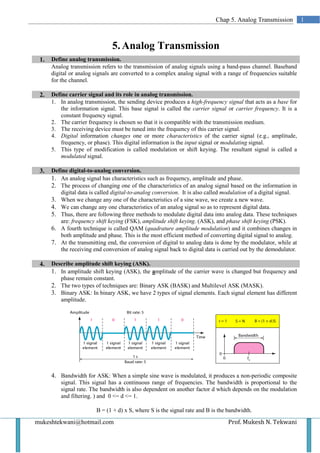
  • 1. Chap 5. Analog Transmission 1 5. Analog Transmission 1. Define analog transmission. Analog transmission refers to the transmission of analog signals using a band-pass channel. Baseband digital or analog signals are converted to a complex analog signal with a range of frequencies suitable for the channel. 2. Define carrier signal and its role in analog transmission. 1. In analog transmission, the sending device produces a high-frequency signal that acts as a base for the information signal. This base signal is called the carrier signal or carrier frequency. It is a constant frequency signal. 2. The carrier frequency is chosen so that it is compatible with the transmission medium. 3. The receiving device must be tuned into the frequency of this carrier signal. 4. Digital information changes one or more characteristics of the carrier signal (e.g., amplitude, frequency, or phase). This digital information is the input signal or modulating signal. 5. This type of modification is called modulation or shift keying. The resultant signal is called a modulated signal. 3. Define digital-to-analog conversion. 1. An analog signal has characteristics such as frequency, amplitude and phase. 2. The process of changing one of the characteristics of an analog signal based on the information in digital data is called digital-to-analog conversion. It is also called modulation of a digital signal. 3. When we change any one of the characteristics of a sine wave, we create a new wave. 4. We can change any one characteristics of an analog signal so as to represent digital data. 5. Thus, there are following three methods to modulate digital data into analog data. These techniques are: frequency shift keying (FSK), amplitude shift keying. (ASK), and phase shift keying (PSK). 6. A fourth technique is called QAM (quadrature amplitude modulation) and it combines changes in both amplitude and phase. This is the most efficient method of converting digital signal to analog. 7. At the transmitting end, the conversion of digital to analog data is done by the modulator, while at the receiving end conversion of analog signal back to digital data is carried out by the demodulator. 4. Describe amplitude shift keying (ASK). 1. In amplitude shift keying (ASK), the amplitude of the carrier wave is changed but frequency and phase remain constant. 2. The two types of techniques are: Binary ASK (BASK) and Multilevel ASK (MASK). 3. Binary ASK: In binary ASK, we have 2 types of signal elements. Each signal element has different amplitude. 4. Bandwidth for ASK: When a simple sine wave is modulated, it produces a non-periodic composite signal. This signal has a continuous range of frequencies. The bandwidth is proportional to the signal rate. The bandwidth is also dependent on another factor d which depends on the modulation and filtering. ) and 0 <= d <= 1. B = (1 + d) x S, where S is the signal rate and B is the bandwidth. mukeshtekwani@hotmail.com Prof. Mukesh N. Tekwani
  • 2. 2 Analog Transmission Minimum bandwidth is obtained when d = 0 or B = S and maximum bandwidth is obtained when d = 1 and B = 2S. 5. From the diagram we observe that the middle of the bandwidth coincides with the carrier frequency fc. So if we have a bandpass channel available we can choose fc so that the modulated signal occupies the bandwidth. 6. Consider a digital signal with a high voltage of 1V and a low voltage of 0 V. We multiply the digital signal by the carrier signal. When the amplitude of the digital signal is 1, the amplitude of the carrier frequency is max and when the amplitude of the digital signal becomes 0, the amplitude of the carrier signal is also 0. 7. In full-duplex transmission, data has to be sent in both directions. The available bandwidth is divided into two with 2 carrier frequencies. The total bandwidth of 100 kHz is divided into 2 parts of 50 kHz each. The available bandwidth for each direction is now 50 kHz. Multilevel ASK: In multilevel ASK, there are more than 2 levels of the digital signal. We can use 4, 8, 16 or more different amplitudes for the signal and modulate the data using 2, 3, 4 or more bits at a time. 5. Describe frequency shift keying (FSK). 1. In FSK, the frequency of the carrier is changed to represent the binary 1 and 0. For binary 0 the carrier frequency will be f1 and for binary 1, the frequency will be f 2. 2. The frequency of the modulated signal is constant for the duration of one signal element (say binary 0) but changes for the next signal element (say binary 1). 3. The peak amplitude and phase remain constant. 4. Bandwidth for FSK: The middle of one bandwidth is f1 while the middle of the other bandwidth is f2. These two bandwidths are Δf apart from the midpoint between the two bands. The difference between the two frequencies is 2 Δf. Multilevel FSK: This is also called multiple FSK. More than 2 frequencies are used. E.g., we can use 4 different frequencies to send 2 bits at a time. To send 3 bits at a time, we use 8 frequencies. Prof. Mukesh N Tekwani mukeshtekwani@hotmail.com
  • 3. Chap 5: Analog Transmission 3 6. Describe phase shift keying (PSK). In phase shift keying, the phase of the carrier is changed to represent different signal elements (1 / 0). The peak amplitude and frequency remain constant. Binary PSK: 1. There are only 2 signal elements one with a phase shift of 0o ; the other with a phase shift of 180 o. 2. The advantage of PSK is that it is less susceptible (or affected) by noise. In PSK, the bit detection depends on the phase of the carrier signal. Although noise can change the amplitude of the carrier, changes in phase are more difficult. Also, PSK is superior to FSK because we donot require 2 carrier signals. 3. Implementing FSK is simple because the signal element with phase 180o is just the complement of the signal element with phase 0. We multiply a polar NRZ data signal with a carrier signal. We represent the 1 bit (positive voltage) by phase starting at 0 . The 0 bit (negative voltage) is represented by a phase starting at 1800 Quadrature PSK: 1. Instead of using only 2 variations of a signal, we use four variations. 2. Each phase shift represents 2 bits. A phase of 00 now represents 00; 900 represents 01; 1800 represents 10; and 2700 represents 11. This technique is called 4-PSK or Q-PSK. The pair of bits represented by each phase is called a dibit. 3. The incoming bits are first passed through a serial to parallel converter. It sends one bit to a modulator and the next bit to another modulator. 4. The 2 signals created by multipliers are sine waves with same frequency but different phases. When these two signals are added, the result is another sine wave which can have phases of 45o, - 45o, 135o, or -135o. Since there are four kinds of signal elements in the output signal, we can send 2 bits per signal element. mukeshtekwani@hotmail.com Prof. Mukesh N. Tekwani
  • 4. 4 Analog Transmission 7. Describe Quadrature Amplitude Modulation (QAM). 1. This modulation technique is a combination of ASK and PSK. 2. In QAM technique, we change two characteristics – the amplitude of one carrier wave and the and the phase of the other carrier wave. 3. The amplitude of the two carrier signals are different. 8. Define analog-to-analog conversion. 1. Analog-to-analog conversion I the representation of analog information by an analog signal. 2. Such a modulation is required if the medium is bandpass. 3. Analog-to-analog conversion is achieved in 3 ways: Amplitude Modulation (AM), Frequency Modulation (FM), and Phase Modulation (PM) 9. Describe Amplitude Modulation (AM) 1. Modulation is defined as the process of combining an input signal and a carrier frequency to produce a signal whose bandwidth is centered around fc. 2. In AM, we use two signals: the carrier signal and the modulating signal. Both are analog signals. 3. The carrier signal is modulated so that its amplitude varies with changes in the amplitude of the modulating signal. 4. The frequency and phase of the carrier signal remain constant, only the amplitude changes. 5. The modulating signal is the envelope of the carrier wave. 6. The bandwidth of the AM signal is two times the bandwidth of the modulating signal. The central frequency is fc. The signal components above and below fc carry the same information. Why is modulation of analog signal necessary? Modulation of an analog signal is necessary for two reasons: a) A higher frequency may be needed for transmission of a signal. The size of the antenna decreases as the carrier frequency increases so a modulated signal is needed. b) Modulation permits frequency division multiplexing. 10. Describe Frequency Modulation (FM) 1. In Frequency Modulation, the frequency of the carrier wave is changed to follow the changing amplitude of the modulating signal. 2. The peak amplitude and phase of the carrier signal remain constant but as the amplitude of the modulating (or information) signal changes, the frequency o the carrier signal also changes. 3. The total bandwidth of the FM signal is given by: BW = 2(1 + β)B, where β is the modulation index Prof. Mukesh N Tekwani mukeshtekwani@hotmail.com
  • 5. Chap 5: Analog Transmission 5 11. Discuss Phase Modulation (PM). 1. In Phase Modulation, the phase of the carrier signal is changed in accordance with the changing amplitude of the modulating signal. 2. The peak amplitude and frequency of the carrier signal remain constant, but the phase of the carrier changes with changes in amplitude of the information signal (or the modulating signal). mukeshtekwani@hotmail.com Prof. Mukesh N. Tekwani