4.electrical resistivity of ferromagnetic nickel
•
3 j'aime•1,771 vues

The document discusses the electrical resistivity of ferromagnetic nickel. It describes how resistivity depends on temperature and is measured using various methods. Resistivity has contributions from phonons, impurities, and magnons that depend on temperature differently. Analysis of the temperature dependence of resistivity can separate these contributions and determine the Curie temperature.

Recommandé
Contenu connexe
Tendances
Tendances (19)
En vedette
Similaire à 4.electrical resistivity of ferromagnetic nickel
Similaire à 4.electrical resistivity of ferromagnetic nickel (20)
Plus de Narayan Behera
Plus de Narayan Behera (20)
Dernier
Dernier (20)
4.electrical resistivity of ferromagnetic nickel
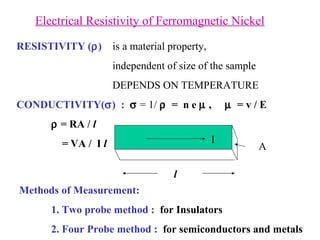
- 1. Electrical Resistivity of Ferromagnetic Nickel RESISTIVITY ( ) is a material property, independent of size of the sample DEPENDS ON TEMPERATURE CONDUCTIVITY( ) : = 1/ = n e , = v / E = RA / l = VA / I l I Methods of Measurement: 1. Two probe method : for Insulators 2. Four Probe method : for semiconductors and metals l A
- 2. = 1/ = n e = n e 2 / m , is mobility of the charge carriers and n is the charge density = v / E = e / m , v is velocity of the carriers is relaxation time or time interval between collisions decreases with increase in T , the temperature and depend on and follow the variation in (T) 1. In metals : T dependence of is vital hence plays an important role. and hence and decrease with rise in T 2. In semiconductors : T dependence of n is vital n = n 0 exp( - E g / K B T) , = n e = 0 exp(- E g / K B T) 3. In insulators, E g is large and hence n is small Formulae
- 3. Band Picture of Solids Band gap E g is ~ 7 eV in Diamond ( Insulator ) ~ 1 ev in Semiconductors Zero in conductors Lennard-Jones potential E(R) = -(A/R m ) +(B/R n ) At R = R 0 , d E/dR = 0
- 6. Four Probe Measurement Insulators – Two Probe Measurement Metals & Semiconductors Four Probe Measurement Block diagram for four-probe conductivity measurement An equivalent circuit for four-probe method
- 7. Pressure contacts for four-probe technique. Four Probe Arrangement Four probe method is used to minimize contribution from contact resistances. V s + = + IR S + V Th V s - = - IR S + V Th V s + - V s - = 2 IR S I = (V R + - V R - ) /R V s + + V s - = 2 V Th V Th is independent of the current direction Any local temperature gradients between points 3 and 4 will generate V Th
- 8. Heating the Sample : The sample is heated using a furnace. The furnace is made by winding a high resistive wire ( Nichrome ) on a muffle which gives out heat ( Joule heating ) as i 2 r when a current i is sent through the furnace wire whose resistance is r. Thermal sensors/ Thermocouples : 1. Commonly used are Pt 100 Ω resistor, or thermocouples There are different types of thermocouples appropriate to sense the temperature at different temperature ranges 2. Chromel- Alumel is the thermocouple used for temps above RT up to 1200 0 C 3. Works on the principle of Seebeck effect. 4. Two junctions , one at O 0 C and the other close to the sample give differential emf. Corresponding temperature is read out from a calibration chart.
- 9. The sample resistance is computed as ( Ohm ) The resistivity is computed as = ( R S A ) / l Sources of Resistivity : 1. Impurities 2. Phonons 3. Magnons Separate the various contributions from total T total ph o mag Correction of thermo emf arising from local heating 0 RT