Development of Navigation and Automated Flight Control System Solutions for M...
X38 Fact Sheet
1. NASA Facts
National Aeronautics and
Space Administration
Dryden Flight Research Center
P.O. Box 273
Edwards, California 93523
Voice 661-276-3449
FAX 661-276-3566
pao@dfrc.nasa.gov FS-2002-04-038 DFRC
The X-38
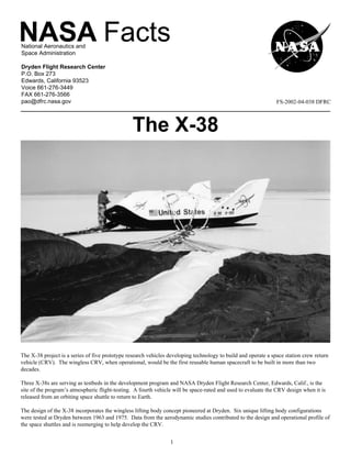
The X-38 project is a series of five prototype research vehicles developing technology to build and operate a space station crew return
vehicle (CRV). The wingless CRV, when operational, would be the first reusable human spacecraft to be built in more than two
decades.
Three X-38s are serving as testbeds in the development program and NASA Dryden Flight Research Center, Edwards, Calif., is the
site of the program’s atmospheric flight-testing. A fourth vehicle will be space-rated and used to evaluate the CRV design when it is
released from an orbiting space shuttle to return to Earth.
The design of the X-38 incorporates the wingless lifting body concept pioneered at Dryden. Six unique lifting body configurations
were tested at Dryden between 1963 and 1975. Data from the aerodynamic studies contributed to the design and operational profile of
the space shuttles and is reemerging to help develop the CRV.
1
2. When operational, the CRV will be an emergency vehicle to
return up to seven International Space Station (ISS)
crewmembers to Earth. It will be carried to the space station in
the cargo bay of a space shuttle and attached to a docking port. If
an emergency arose that forced the ISS crew to leave the space
station, the CRV would be undocked and — after a deorbit
engine burn — the vehicle would return to Earth much like a
space shuttle. The vehicle’s life support system will have a
duration of about seven hours. A steerable parafoil parachute
would be deployed at an altitude of about 40,000 feet to carry it
through the final descent and the landing. The CRV is being
designed to fly automatically from orbit to landing using onboard
navigation and flight control systems. Backup systems will allow
the crew to pick a landing site and steer the parafoil to a landing,
if necessary.
The first test flight of an X-38 from an orbiting space shuttle is
currently scheduled for April 2002. The first of the four planned
CRVs is expected to be docked and operational at the Interna-
tional Space Station in the year 2006.
NASA’s Johnson Space Center, Houston, Texas, manages the
X-38 program and works with personnel from Dryden Flight
Research Center, and Langley Research Center, Hampton, Va.
The Vehicles
The X-38 design closely resembles the X-24A lifting body flown
at Dryden from April 1969 to 1971. Wingless lifting bodies
generate aerodynamic lift — essential to flight in the atmosphere
— from the shape of their bodies. enclose the chamber and the exterior surfaces will be covered
with a Thermal Protection System (TPS) to withstand the heat
The 28 research missions flown by the X-24A helped demon- generated by air friction as the vehicle returns to Earth through
strate that hypersonic vehicles like the space shuttle returning the atmosphere. The TPS will be similar to materials used on the
from orbital flight could be landed on conventional runways space shuttles, but much more durable — carbon and metallic-
without power. The X-24A was modified in 1970 and designated silica tiles for the hottest regions, and flexible blanket-like
the X-24B in 1971, the last lifting body configuration was tested material for areas receiving less heat during atmospheric reentry.
in the 12-year research program at Dryden.
Much of the technology being used in the X-38 is off-the-shelf,
The three prototype X-38s used in the atmospheric flight testing but that doesn’t mean it is old or out-dated.
program are 24.5 feet long, 11.6 feet wide, and 8.4 feet high,
approximately 80 percent of the planned size of the CRV. The The flight control computer and the flight software operating
prototypes are designated V131, V132, and V131R. The V131 system are commercially developed and used in many aerospace
prototype was modified for additional testing beginning in the applications. The space-flight X-38 prototypes will have newly
summer of 2000 and now carries the designation V131R. A designed actuators.
fourth prototype, V133, will incorporate the exact shape and size
of the planned CRV. The current electro-mechanical actuators that move the vehicle’s
flight control surfaces for pitch, yaw, and roll control have been
The atmospheric test vehicles, built by Scaled Composites, used on earlier NASA, Air Force, and Navy aeronautical research
Mojave, Calif., are shells made of composite materials such as projects.
fiberglass and graphite epoxy, and strengthened with steel and
aluminum at stress points. Vehicle weights range from 15,000 Inertial navigation and global positioning systems, similar to
pounds to about 25,000 pounds. They land on skids — reminis- units used on aircraft throughout the world, will be linked to the
cent of the famed X-15 research aircraft — instead of wheels. vehicle’s flight control system to automatically steer the vehicles
along the correct reentry path during atmospheric tests and during
The fourth X-38 in the program will be V201, the space-rated the space flight test.
vehicle that will be flown back to Earth from an orbiting space
shuttle. NASA is constructing it at the Johnson Space Center. Its Using global positioning already programmed into the navigation
inner compartment, representing the crew area, will be a pressur- system, the flight control computer becomes the autopilot that
ized aluminum chamber. A composite fuselage structure will flies the vehicle to a predetermined landing site.
2
3. of the main parafoil and landing. Data from the two flights have
The U.S. Army originally developed the design of the parafoil helped improve drogue deployment and led to landing skid
that deploys in the atmosphere and carries the X-38 to Earth. The improvements.
shroud lines of the steerable parachute are attached to risers
linked to actuators controlled by the flight control system. The Following the two flights, Vehicle 131 was returned to Scaled
flight control system receives inputs from the inertial navigation Composites to be modified into the actual shape of the future
and global positioning units to determine where the vehicle is and CRV. The vehicle, now designated V131R, has been delivered to
steers the parachute until it gets to its destination. During the the Johnson Space Center where navigation, guidance, flight
descending flight, the direction and speed of any winds are control, and parachute deployment systems are being installed.
calculated by the flight control system and steerage corrections The modified vehicle will have the aerodynamics and atmo-
are automatically made. The parafoil guidance system also spheric flight capabilities of the full-size CRV in the summer of
predicts wind direction across the landing zone and automatically 2000 when a series of up to six atmospheric test flights is
turns the vehicle up wind for a safe landing. scheduled to begin.
During atmospheric tests at Dryden, the X-38s are dropped from Vehicle 132, which also has the bulbous X-24A shape, carries a
the wing pylon of NASA’s B-52 launch aircraft at altitudes full flight control system, including electro-mechanical control
ranging from 25,000 feet to 45,000 feet. The higher altitudes surface actuators similar to those to be used on the CRV. V132
give engineers more time to study vehicle aerodynamics and was test flown in March and July of 1999 with its final flight on
handling qualities during its controlled, unpiloted gliding descent March 30, 2000. It was the highest, fastest and longest flight to
before the steerable parachute is deployed. date.
GenCorp Aerojet, Sacramento, Calif., is developing the propul- The primary objectives of the flights are testing and validating
sion unit that will be used during the X-38 de-orbit tests. After the parachute deployment and steering systems, along with the
the X-38 is released from the shuttle cargo bay, the small aft- vehicle’s automatic flight control system.
mounted deorbit rocket will be fired to slow the vehicle’s speed
to let gravity begin pulling it back to Earth. The rocket unit will Atmospheric test vehicle 133 is representative of the size and
be jettisoned during the descent phase. The same deorbit propul- shape of the planned CRV. It will be used to fully test the
sion unit will more than likely be used on CRVs operating with spacecraft’s integrated avionics, guidance, and flight control
the International Space Station. systems, while studying the vehicle’s aerodynamics, handling
qualities, and the reliability of the parachute and its steering
A Flush Air Data Sensing System (FADS) developed at Dryden system.
is being used on the X-38 to collect vehicle air speed and attitude
(pitch and yaw) data. This information is fed into the flight
control computer to maintain the desired flight path. FADS uses Space-rated Vehicle 201 will be ready for its test flight from an
tiny ports to collect the aerodynamic data instead of using orbiting space shuttle in the spring of 2002. The flight will be a
conventional probes that extend into the air stream. FADS data is final proof-of-concept test for the CRV development program.
also monitored by test personnel on the ground during test flights.
Results from the uninhabited re-entry test will contribute signifi-
A bank of storage batteries will provide electrical power on each cantly to the assessment of safety and reliability of the CRV
of the X-38 test vehicles to operate the avionics, navigation, before an operational vehicle is used to carry humans from the
guidance, flight control, and parachute steering systems. ISS back to Earth.
The X-38 that will be test flown from the space shuttle and the The Dryden Connection
future CRV itself will use nitrogen gas attitude control systems
for guidance and control during flight in space where conven- The connection between Dryden and the X-38 prototypes begins
tional control surfaces are ineffective. with the lifting body program of the 1960s and 70s, from which
the CRV concept emerged. It now encompasses engineers
X-38 Test and Development Schedule involved in flight test planning and technicians working on the
design and integration of vehicle systems. Dryden personnel help
X-38 flight-testing began in March 1998 with Vehicle 131 and it operate and staff mission control centers during test flights, and
will continue atmospheric testing with Vehicle 133 through 2004 provide expertise in the areas of flight research, aerodynamics,
or 2005, when space-rated Vehicle 201 is released from an and flight-control systems.
orbiting space shuttle for a test trip back to Earth.
The concept of using a parafoil to autonomously recover a
Vehicle 131 was taken aloft by the B-52 launch aircraft for spacecraft from orbit and make a precision landing was success-
several captive-carry flights beginning in July 1997 to study its fully tested at Dryden between October 1991 and December 1996
aerodynamics while attached to the aircraft’s wing pylon. Two in a project called the Spacecraft Autoland. In 1995, this concept
brief free flights followed, in March 1998 and February 1999, to was extended to flying a one-sixth scale X-38 using a small
study launch characteristics and to assess the operation of the parafoil.
parachute, from deployment of the small drogue through reefing
3
4. Precursors to actual X-38 flights were made to evaluate vehicle the V201 flight test, with an option for a second unit. There is a
control under the parafoil using a four-foot model of the vehicle. second option in the contract for five operational flight units if
The instrumented test article was carried into the air and dropped the project is approved and the operational CRVs are built. All
13 times from a Cessna U-206 at California City, Calif., near options would have a potential value of $71.9 million.
Dryden.
Total projected cost to develop and flight test the X-38s is
One of the most prominent components of X-38 support is the B- approximately $700 million. Using available technology and off-
52 launch aircraft used to take the X-38 to drop altitude. The the-shelf equipment has significantly reduced project costs, when
aircraft, older than any B-52 still flying, is the same launch compared to other space vehicle projects. Original estimates to
aircraft used in the X-15 program and was the so-called “mother build a capsule-type CRV were more than $2 billion in total
ship” for all lifting bodies in that nine-year research program. development cost.
The aircraft has been reconfigured to support a variety of crewed
and uncrewed research vehicles that needed to be carried aloft to About 100 people, mostly civil servants, are currently working on
begin their flights back to the dry lake or conventional runways the X-38 project at the Johnson, Dryden, and Langley centers.
of Edwards Air Force Base. The X-38 project is the first in which a prototype space vehicle
has been built-up in-house by NASA at the Johnson Space
The electro-mechanical actuators that move the flight control Center, rather than by a contractor. This approach has advan-
surfaces on the X-38s are a product of aeronautical research at tages. By building the vehicles in-house, NASA engineers have a
Dryden. They were developed as space and weight-savers for better understanding of the problems contractors experience
all-electric flight control systems on new aircraft. when they build vehicles for NASA.
Dryden’s involvement with the X-38s also extends to the The agency’s X-38 team will have a detailed set of requirements
personnel who have helped develop the flight software that will for the contractor to use when the operational CRVs are built.
be used on V201, and its vehicle’s guidance, flight control, and This type of hands-on work dates back to the National Advisory
flight termination systems. Committee for Aeronautics (NACA), predecessor agency of
NASA.
Pre- and post-flight vehicle inspections are conducted by a team
of Dryden maintenance and engineering specialists accustomed The Future
to working with unconventional crewed and uncrewed research
vehicles. Once CRVs are operational at the International Space Station,
modified follow-on versions of the vehicles could be used for
Through the entire X-38 planning and development program, brief science missions after being placed in orbit by Space
Dryden engineers and technicians have served as consultants in a Shuttles or expendable booster rockets such as the American
variety of disciplines. These include vehicle handling and flying Delta series and the French Ariane.
qualities, guidance and control systems, test planning, and
analyzing the flight test data.
Project History and Participants
The X-38 project began at the Johnson Space Center in early
1995 using data from past lifting-body programs and the U.S.
Army’s Guided Precision Delivery System tests from Yuma
Proving Grounds in Yuma, Ariz. Flight tests began in Yuma
using pallets dropped from an aircraft to study and develop the
steerable parafoil system.
In early 1996, a contract was awarded to Scaled Composites for
the construction of two atmospheric test vehicles. The first
vehicle, V131, was delivered to the Johnson Space Center in
September 1996, where it was outfitted with avionics, computer
systems, and other hardware in preparation for its initial flight
tests at Dryden. The second vehicle was delivered to JSC in
December 1996.
In October 1998, Scaled Composites received an additional
contract to modify V131 into V131R.
GenCorp Aerojet, Sacramento, Calif., is designing and building a
de-orbit propulsion unit that will be used on V201. The base
contract, valued at $16.4 million, is for one propulsion stage for X-38 three view.
4