SlideShare a Scribd company logo
1 of 9
Download to read offline
Source:PaulJohnston-Knight
Introduction
Federal laws and regulations require
Federal agencies to reduce water use
and improve water efficiency. Namely,
Executive Order 13514 Federal
Leadership in Environmental, Energy,
and Economic Performance, requires an
annual two percent reduction of water use
intensity (water use per square foot of
building space) for agency potable water
consumption as well as a two percent
reduction of water use for industrial,
landscaping, and agricultural applica-
tions. Cooling towers can be a significant
source of water use for both of these cat-
egories of water use at Federal facilities.
To realize potential savings it is essential
for Federal agencies understand the key
components of cooling towers and how
to improve water efficiency of the system
as a part of a comprehensive approach to
water management.
In this Fact Sheet:
•	 Introduction
•	 Overview
•	 Structure
•	 Basic Cooling Tower Terms
•	 Types of Towers
•	 Important Properties of Water
•	 System Calculations
•	 Factors That Limit Cycles of Concentration
•	 System Concerns
•	 Treatment Options
Overview
Cooling towers are an integral component
of many refrigeration systems, providing
comfort or process cooling across a broad
range of applications. They are the point
in the system where heat is dissipated to
the atmosphere through the evaporative
process, and are common in industries
such as oil refining, chemical process-
ing, power plants, steel mills, and many
different manufacturing processes where
process cooling is required. They are
also commonly used to provide comfort
cooling for large commercial buildings
including airports, office buildings,
conference centers, hospitals, and hotels.
Cooling tower structures vary greatly
in size and design, but they all function
to provide the same thing: liberation of
waste heat extracted from a process or
building system through evaporation of
water. In technical terms, cooling towers
are engineered and designed based on
a specified cooling load, expressed in
refrigeration tons.(1)
The cooling load
is determined by the amount of heat
that needs to be extracted from a given
process or peak comfort cooling demand.
The cooling tower must be adequately
sized to reject this same amount of heat
to the atmosphere.
Cooling towers are used to reject heat
through the natural process of evapora-
tion. Warm recirculating water is sent to
the cooling tower where a portion of the
water is evaporated into the air passing
through the tower. As the water evapo-
rates, the air absorbs heat, which lowers
the temperature of the remaining water.
This process provides significant cool-
ing to the remaining water stream that
collects in the tower basin where it can be
pumped back into the system to extract
more process or building heat, thereby
allowing much of the water to be used
repeatedly to meet the cooling demand.
The amount of heat that can be rejected
from the water to the air is directly tied
to the relative humidity of the air. Air
with a lower relative humidity has a
greater ability to absorb water through
evaporation than air with a higher relative
humidity, simply because there is less
water in the air. As an example, consider
cooling towers in two different locations–
one in Atlanta, Georgia, and another in
Albuquerque, New Mexico. The ambient
air temperature at these two locations
may be similar, but the relative humidity
in Albuquerque on average will be much
lower than that of Atlanta’s. Therefore,
the cooling tower in Albuquerque will be
able to extract more process or building
heat and will run at a cooler temperature
because the dry desert air has a greater
capacity to absorb the warm water.
Cooling towers can be split into two
distinct categories: open circuit (direct
contact) and closed circuit (indirect)
systems. In open circuit systems the recir-
culating water returns to the tower after
(1)	 One ton of refrigeration is equal to 12,000 Btu/hour.
continued >
Cooling Towers:
Understanding Key
Components of
Cooling Towers and
How to Improve
Water Efficiency
FEDERAL ENERGY MANAGEMENT PROGRAM
gathering heat and is distributed across
the tower where the water is in direct
contact with the atmosphere as it recircu-
lates across the tower structure. Closed
circuit systems differ in that the return
fluid (often water, or sometimes water
mixed with glycol) circulates through the
tower structure in a coil, while cooling
tower water recirculates only in the tower
structure itself (see Figure 1). In this case,
the return fluid is not exposed directly to
the air.
Structure
Cooling towers are the primary com-
ponent used to exhaust heat in open
recirculating cooling systems. They
are designed to maximize air and water
contact to provide as much evaporation
as possible. This is accomplished by
maximizing the surface area of the water
as it flows over and down through the
tower structure. Figure 2 illustrates the
different components of a cooling
tower structure.
First, the water is distributed evenly
across the top of the cooling tower
structure. Tower distribution decks can
be a series of spray nozzles oriented up
or down (like a landscaping sprinkler
system) to uniformly distribute the water
over the tower structure. In some cases,
the distribution deck may just be a series
of holes through which the water falls
onto the tower structure. Regardless
the distribution deck must uniformly
apportion the recirculating water across
the tower structure. Broken nozzles or
plugged orifices will impede uniform
distribution across the tower structure,
negatively impacting the overall heat
exchange capacity of the system.
As the water falls from the distribution
deck, the surface area is further expanded
in the fill section. Older tower systems
may feature splash bars made of plastic,
fiberglass, or wood that serve to break the
falling water into tiny droplets. In recent
years, many different forms of labyrinth-
like packing or film fill have been
incorporated. The closely packed nature
of film fill causes the water to travel
through this portion of the tower in thin
streams, improving thermal efficiency
and the evaporation rate, thereby increas-
ing heat rejection (see Figure 3).
There are several variations of film fill
geometries commercially available,
and though they do greatly increase the
heat rejection rate over splash-type fills,
they are also much more susceptible to
fouling, scaling, and microbiological
growth (these are discussed in greater
detail in the System Concerns section).
Development of any of these problems
greatly reduces the cooling efficiency
and in severe cases can collapse portions
of the tower fill or tower structure. To
avoid this, film fill should be inspected
routinely to ensure it is clean and free of
debris, scale, and biological activity.
To minimize losses due to drift and help
direct airflow into the tower, louvers and
drift eliminators are commonly used.
Louvers are most often seen along the
sides of the tower structure, while drift
eliminators reside in the top section of the
tower to capture entrained water droplets
that may otherwise leave through the
stack. Damaged or incorrectly oriented
louvers along with damaged drift elimi-
nators will lead to excessive losses due to
drift from the tower structure. Therefore,
louvers and drift eliminator sections
should be routinely inspected and
repaired to ensure optimal water usage.
After the water passes through the fill
it cascades down to a collection basin
at the base of the tower structure. From
the basin the cold water can be pumped
back into the system to extract process
or comfort cooling needs and begin the
cycle all over again.
By design, cooling towers consume large
volumes of water through the evapora-
tion process to maintain comfort cooling
or process cooling needs, although they
use significantly less water than similar
capacity once-through cooling systems.
Because the evaporative loss is water
containing little to no dissolved solids,
the water remaining in the cooling tower
becomes concentrated with dissolved
solids, which can lead to scaling and
corrosive conditions. To combat these
problems, water with high total dissolved
solid content must be drained from the
system via “blowdown.” The associated
losses caused by blowdown, evaporation,
drift, and system leaks must be accounted
for by system make-up requirements.
Figure 4 illustrates these water system
flow locations in generic terms.
Figure 1. Example of a Closed Circuit Cooling
Tower.
Figure 2. Overview of Cooling Tower Structure
Components.
Figure 3. Relative Thermal Performance of
Different Types of Fill.
continued >
2	 FEDERAL ENERGY MANAGEMENT PROGRAM
Basic Cooling Tower Terms
Blowdown – Water discharged to remove
high mineral content system water,
impurities, and sediment.
Cycles of Concentration – Technical
term used to describe the mass flow rela-
tionship between the amount of system
feed water and the amount of blowdown
sent down the drain. Also referred to as
concentration ratio, cycles of concentra-
tion correlates to the effective use of
water in your system to provide heating
or cooling needs. High cycles of concen-
tration are directly related to low levels of
water loss from your system.
Dissolved Solids – The amount of dis-
solved minerals present in the water.
Drift – Droplets of water entrained in the
air leaving the top of the tower, or blown
from the side of the tower by crosswinds.
Make-up – Water supply needed to
replace all losses due to evaporation,
leaks, or discharge in cooling systems.
Types of Towers
Cooling Towers – Cooling towers are
classified by the direction of air flow
(counter-flow or cross-flow) and the
type of draft (mechanical or natural).
Mechanical Draft Towers –
Mechanical draft towers have air
forced through the structure by a fan.
The air flow can be pushed through
by fans located at the base of the tower
(referred to as forced draft), or pulled
through by fans located at the top
of the tower (referred to as induced draft).
Induced draft towers tend to be larger
than forced draft units.
Natural Draft Towers – Natural draft
towers are designed to move air up
through the structure naturally without
the use of fans. They use the natural law
of differing densities between the ambient
air and warm air in the tower. The warm
air will rise within the chimney structure
because of its lower density drawing cool
ambient air in the bottom portion. Often
times these towers are very tall to induce
adequate air flow, and have a unique
shape giving them the name “hyperbolic”
towers (see Figure 5).
Cross-Flow Towers – Cross-flow cooling
towers are structured so that air flows
horizontally across the falling water
(see Figure 6). This design provides less
resistance for the air flow, thereby reduc-
ing the fan horsepower required to meet
the cooling demand. These towers usually
feature gravity-fed water distribution
decks that are either open and uncovered,
or that are covered to limit algae growth
and debris from getting into the distribu-
tion deck. Gravity-fed distribution decks
have evenly spaced openings that the
water drops through to be spread across
the tower fill.
Counter-flow Towers – Counter-flow
cooling towers have upward air flow that
directly opposes the downward flow of
the water providing very good thermal
efficiency because the coolest air contacts
the coolest water (in the bottom section
of the tower structure).
Important Properties of Water
A primary consideration for the operation
of the cooling tower system is the water
quality of the make-up source. Differing
sources present differing challenges.
Surface water sources include lakes,
rivers, and streams, while groundwater
sources consist of wells or aquifers.
Depending on the location, surface water
sources will have seasonal variations
and can carry high levels of suspended
silt and debris that cause fouling if
not removed by pre-filtration systems.
Groundwater sources don’t have the
seasonal variations that surface water
sources have, but depending on the
geology of the region, they can have high
levels of dissolved minerals that contrib-
ute to scale formation or corrosion in the
Figure 4. Illustration of Water Flow Across a Cooling Tower.
Figure 5. Hyperbolic Cooling Towers
(Source: Victor Vizu).
Figure 6. Example Cross-flow Cooling Tower.
continued >
FEDERAL ENERGY MANAGEMENT PROGRAM	 3
cooling system. Recently, water reuse
has become popular and many cooling
systems are being supplied reclaimed
effluent or discharge water from other
processes. While water reuse is a wise
resource option, consideration should be
made regarding the quality of the water
and how that will impact the efficient
operation of the cooling system, and
the system’s ability to meet the required
cooling demand.
Whether the source water is surface,
ground, or reuse, in nature there are a few
basic water quality considerations that
should be understood.
pH – pH is a measurement of how acidic
or how alkaline a substance is on a scale
of 0 to 14. A pH of 7.0 is neutral (the
concentration of hydrogen ions is equal
to the concentration of hydroxide ions),
while measurements below 7.0 indicate
acidic conditions, and measurements
above 7.0 indicate basic or alkaline
conditions. The pH scale is logarithmic
(each incremental change corresponds
to a ten-fold change in the concentration
of hydrogen ions), so a pH of 4.0 is ten
times more acidic than a pH of 5.0 and
one hundred times more acidic than a pH
of 6.0. Similarly, a pH of 9.0 is ten times
more basic or alkaline than a pH of 8.0
and one hundred times more alkaline than
a pH of 7.0.
Hardness – Hardness refers to the pres-
ence of dissolved calcium and magne-
sium in the water. These two minerals are
particularly troublesome in heat exchange
applications because they are inversely
soluble – meaning they come out of solu-
tion at elevated temperatures and remain
soluble at cooler temperatures. For this
reason calcium and magnesium-related
deposits will be evident in the warmest
areas of any cooling system, such as the
tubes or plates of heat exchangers, or in
the warm top regions of the cooling tower
fill where most of the evaporation occurs.
Alkalinity – Alkalinity is the presence
of acid neutralizing, or acid buffering
minerals, in the water. Primary contribu-
tors to alkalinity are carbonate (CO3
-2
),
bicarbonate (HCO3
-
), and hydroxide
(OH-
). Additional alkaline components
may include phosphate (PO4
-3
),
ammonia (NH3
), and silica (SiO2
),
though contributions from these ions
are usually relatively small.
Conductivity – Conductivity is a mea-
surement of the water’s ability to conduct
electricity. It is a relative indication of
the total dissolved mineral content of the
water as higher conductivity levels cor-
relate to more dissolved salts in solution.
Conversely, purified water has very little
dissolved minerals present meaning the
conductivity will be very low.
System Calculations
To properly operate and maintain a
cooling tower, there needs to be a basic
understanding of the system water’s use.
Water use of the cooling tower is the
relationship between make-up, evapora-
tion, and blowdown rates. There are a
couple simple mathematical relationships
between the blowdown rate, evaporation
rate, make-up rate, and cycles of concen-
tration of a cooling tower that are very
useful to understand the principal flow
rates. The first relationship illustrates
the overall mass balance consideration
around a given cooling tower:
(1)	 Make-up = Blowdown+ Evaporation
In this case, the blowdown accounts for
all system losses including leaks and
drift, except for evaporation.
The second principal relationship defines
cycles of concentration in terms of make-
up flow and blowdown flow:
(2)	 Cycles of Concentration = Make-up
	 ÷ Blowdown
This equation can be rearranged to either
of the following to solve for the make-up
rate or blowdown rate:
(3)	 Blowdown = Make-up ÷ Cycles of
	Concentration
(4)	 Make-up = Cycles of Concentration
	 × Blowdown
If the evaporation rate and cycles of
concentration are known, the blowdown
rate can then be determined by substitut-
ing equation 4 into equation 1:
(5)	 Cycles of Concentration ×
	 Blowdown = Blowdown +
	Evaporation
Solving for blowdown:
(6)	 Blowdown = Evaporation ÷
	 (Cycles of Concentration -1)
Also, if the blowdown rate and cycles of
concentration are known, the make-up
rate can be determined by solving equa-
tion 4, and then the evaporation rate can
be determined by solving equation 6 for
evaporation:
(7)	 Evaporation = Blowdown ×
	 (Cycles of Concentration – 1)
Factors That Limit Cycles
of Concentration
Increasing cycles of concentration saves
water because it essentially means that
water is being recirculated longer through
the system before being blown down. But
as levels of dissolved minerals elevate
with higher cycles of concentration, scal-
ing and corrosion potential also increase.
All dissolved minerals have a saturation
limit that, if exceeded, will lead to scale
formation.(2)
Additionally, high levels of
dissolved minerals (high cycles of con-
centration) increases the water’s tendency
to be corrosive (corrosion is discussed
in greater detail below). Chemical and
mechanical treatment programs allow
the thresholds of scaling tendencies and
corrosion to be pushed; however, limits
still persist necessitating management of
dissolved minerals (conductivity) levels
through elimination of high mineral
content water through blowdown. The
following section discusses these
concerns in greater detail.
System Concerns
Cooling towers are dynamic systems
because of the nature of their operation
and the environment they function within.
Tower systems sit outside, open to the
elements, which makes them susceptible
to dirt and debris carried by the wind.
Their structure is also popular for birds
and bugs to live in or around, because
(2)	 Scaling will occur predominantly in the heat exchangers and in the fill-section of the tower structure, but may also occur in the piping or on the tower distribution deck.
continued >
4	 FEDERAL ENERGY MANAGEMENT PROGRAM
of the warm, wet environment. These
factors present a wide range of opera-
tional concerns that must be understood
and managed to ensure optimal thermal
performance and asset reliability. Below
is a brief discussion on the four pri-
mary cooling system treatment concerns
encountered in most open-recirculating
cooling systems.
Corrosion – Corrosion is an electro-
chemical or chemical process that leads
to the destruction of the system metal-
lurgy. Figure 7 illustrates the nature of a
corrosion cell that may be encountered
throughout the cooling system metal-
lurgy. Metal is lost at the anode(3)
and
deposited at the cathode.(4)
The process is
enhanced by elevated dissolved mineral
content in the water and the presence of
oxygen, both of which are typical of most
cooling tower systems.
There are different types of corrosion
encountered in cooling tower systems
including pitting, galvanic, microbiologi-
cally influenced (Figure 8), and erosion
corrosion, among others (expanded
discussion is available at www.gewater.
com/handbook/cooling_water_systems/
ch_24_corrosion.jsp). Loss of system
metallurgy, if pervasive enough, can
result in failed heat exchangers, piping,
or portions of the cooling tower itself.
Scaling – Scaling is the precipitation of
dissolved minerals components that have
become saturated in solution. Figure 9
illustrates calcium carbonate scale
collecting on a faucet head. Factors that
contribute to scaling tendencies include
water quality, pH, and temperature. Scale
formation reduces the heat exchange abil-
ity of the system because of the insulating
properties of scale, making the entire
system work harder to meet the cooling
demand. An expanded discussion for
scaling is available at www.gewater.
com/handbook/cooling_water_systems/
ch_25_deposit.jsp.
Fouling – Fouling occurs when sus-
pended particles fall out of solution
forming deposits. Common foulants
include organic matter, process oils, and
silt (fine dirt particles that blow into the
tower system, or enter in the make-up
water supply). Factors that lead to fouling
are low water velocities(5)
, corrosion, and
process leaks. Fouling deposits, similar to
scale deposits, impede the heat exchange
capabilities of the system by providing an
insulating barrier to the system metal-
lurgy. Fouling in the tower fill can plug
film fill reducing the evaporative surface
area, leading to lower thermal efficiency
of the system.
Microbiological Activity –
Microbiological activity is micro-
organisms that live and grow in the cool-
ing tower and cooling system. Cooling
towers present the perfect environment
for biological activity due to the warm,
moist environment. There are two distinct
categories of biological activity in the
tower system. The first being plank-
tonic, which is bioactivity suspended, or
floating in solution. The other is sessile
biogrowth, which is the category given
to all biological activity, biofilms, or
biofouling that stick to a surface in the
cooling system. Biofilms are problematic
for multiple reasons. They have strong
insulating properties, they contribute
to fouling and corrosion, and the bi-
products they create that contribute to
further micro-biological activity. They
can be found in and around the tower
structure, or they can be found in chiller
bundles, on heat exchangers surfaces,
(see Figure 10), and in the system piping.
Additionally, biofilms and algae mats are
problematic because they are difficult
to kill. Careful monitoring of biocide
treatments, along with routine measure-
ments of biological activity are important
to ensure bio-activity is controlled and
limited throughout the cooling system.(6)
(3)	 The anode in a corrosion cell is defined as the site where metal is lost from the system structure and goes into solution.
(4)	 The cathode in a corrosion cell is defined as the site where the metal lost at the anode is deposited.
(5)	 Low water velocities may occur in poorly designed or improperly operated heat exchangers, in the cooling system piping, or in locations across the tower fill where uniform distribution
is not maintained.
(6)	 Beyond the operational and mechanical problems bioactivity causes in cooling tower systems, there is a human health issue if the system develops a specific bacterium
known as Legionella. For more information regarding Legionella and Legionnaires’ disease go to www.cdc.gov/legionella/patient_facts.htm.
Figure 7. Example of a Corrosion Cell.
Figure 8. Microbiologically Influenced Corrosion
(Source: Taprogge GmbH).
Figure 9. Calcium Carbonate Scale
(Source: Hustvedt).
Figure 10. Biofouled Heat Exchanger
(Source: Taprogge GmbH).
continued >
FEDERAL ENERGY MANAGEMENT PROGRAM	 5
Treatment Options
Traditional water treatment programs are
designed and implemented to account
for the system concerns outlined above.
This ensures the tower system operates
optimally and achieves the needed cool-
ing requirement. These programs consist
of chemical additives including corrosion
inhibitors, dispersants, scale inhibitors,
and biocides that function to protect the
cooling system and keep heat exchange
surfaces clean and free of deposits or
bio-films. When this is accomplished,
maximum cycles of concentration can be
achieved, and the cooling system can be
operated at peak efficiency both in terms
of water use and energy use. Beyond
traditional water treatment programs
there are options to build upon the current
program, improve the current program,
or replace the current program.
Water Modeling – Software platforms
provide the ability to model the system’s
scaling tendencies, corrosion characteris-
tics, and view optimal chemical applica-
tion (also referred to as “dosing”).
This can be a powerful tool to better
understand if the system is operating at
the maximum cycles of concentration
possible, to see problem points in the sys-
tem (low flow velocity, high temperature
heat exchangers, for example), and to see
impacts of varying water characteristics.
Additionally, these modeling platforms
allow a facility to review the potential
impact of integrating water reuse
resources, altering chemical treatment
programs, or variations to certain opera-
tional parameters such as pH set-point.
In some cases, local and regional water
treatment professionals may have the
capability to supply similar modeling
results as a part of your existing water
treatment program or for a consulting fee.
Green Chemistries – “Green” chemistry
programs exist primarily to replace tradi-
tional treatments that have been deemed
harmful for environmental reasons.
“Green” chemistries often don’t result in
improved thermal efficiency or reduced
water consumption, but provide environ-
mental compliance and reduced dis-
charge of harmful or illegal substances.
Examples of “green” chemistry programs
include polysilicate corrosion inhibitors
(used for many years in potable water
systems), polyaspartic acid dispersants,
and hydrogen peroxide for biocide appli-
cations. Another biocide that received the
1997 Environmental Protection Agency
(EPA) Green Chemistry Award is THPS
– tetrakis (hydroymethyl) phosphonium
sulfate.(7)
Automation – Automation systems are
available providing a broad range of
capacities to control single or multiple
parameters in the cooling system such as
conductivity and blowdown control, pH
control, and real-time chemical monitor-
ing and dosing.
Blowdown controllers are available from
several different commercial suppliers
and offer a range of control points from
simple conductivity/blowdown control,
to timed or meter relay chemical dosing.
Many of them incorporate water meter
inputs and alarm relays if threshold
measurements are exceeded.
Blowdown controllers offer continuous
monitoring and control of the blowdown
of the tower system. This ensures high
conductivity is avoided, minimizing scal-
ing and corrosive conditions and mini-
mizes excessive blowdown which wastes
water. Figures 11 and 12 provide two
opposing trends – one showing manual
blowdown control and the other showing
blowdown controlled with a conductivity
controller. The charts illustrate the impact
of implementing blowdown control-
lers, revealing conductivity rates that
stay much closer to the ideal set point
compared to manual control.
More robust automation platforms are
also available from several manufacturers
that provide system-wide monitoring
and dosing. These platforms are scalable
depending on the need, but offer
conductivity/blowdown control, pH con-
trol, real-time chemical monitoring and
dosing, continuous corrosion monitoring,
web-enabled reporting, and alarm relays.
The benefit of these systems is tightened
control of the various control points of
the water treatment program, not only
eliminating excessive water use and high
cycle conditions, but also controlling
chemical residuals and treatment dosing
based on real-time corrosion and scaling
indices. In trend terms, similar results to
the conductivity improvements shown
by Figures 11 and 12 can be achieved
on chemical treatment residuals, pH set
point and acid feed, biocide dosing, and
corrosion monitoring. Figures 13 and 14
illustrate the performance improvement
real-time dosing achieves on chemical
residuals, ensuring the proper dosage of
corrosion and scale inhibitors at all times
and eliminating overfeed or underfeed of
(7)	 To view the details of the THPS Green Chemistry Award go to www.epa.gov/gcc/pubs/pgcc/winners/dgca97.html. The complete list of recipients for the EPA’s Green Chemistry Awards
is available at www.epa.gov/gcc/pubs/pgcc/past.html.
Figure 11. Conductivity Trend for Manual or Timed Blowdown Control.
continued >
6	 FEDERAL ENERGY MANAGEMENT PROGRAM
these products. These platforms offer
web-enabled reporting interfaces so
operators and maintenance staff can
view tower performance remotely.
Additionally, alarms for out-of-
compliance measurements can be sent
via email or text message alerting
maintenance or operations personnel
so corrective actions can be taken.
Filtration – Filter systems are nothing
new to industrial water systems, and
have been used as pre-treatment in many
different applications for many years.
In recent years, side-stream filtration
systems have become popular among
many water treatment professionals.
They function to remove suspended
solids, organics, and silt particles down
to 0.45 microns from a portion or all of
the system water on a continual basis,
thereby reducing fouling, scaling and
microbiological activity. This allows the
cooling system to work more efficiently
and often reduces the amount of water
blown down. However, the net impact on
water consumption must consider the fact
that these platforms require back-washing
to clean the filter system. The amount of
water used to regenerate the filter system
should be added to the water lost due to
evaporation and blowdown.
Softening – Softeners function to remove
hardness (calcium and magnesium) from
the make-up water, or can be incorpo-
rated as a side-stream system to soften a
portion of the water continuously. This
effectively manages (or eliminates) the
amount of calcium and magnesium in
the tower bulk water, thereby reducing
the scaling potential of calcium and
magnesium related deposits. By reducing
or eliminating the scaling potential of
calcium and magnesium, higher attention
should be given to corrosion monitoring
and the corrosive characteristics of the
water. Calcium and magnesium function
naturally as corrosion inhibitors, so if
they are minimized or removed from
the water, the corrosive conditions will
increase putting more importance on
the corrosion management program and
tighter requirements on pH and alkalinity
control.
Figure 12. Conductivity Trend for a System Using a Blowdown Controller.
Figure 13. Chemical Residuals Trend for Timed Feed.
Figure 14. Chemical Residuals with Real-Time Dosing.
continued >
FEDERAL ENERGY MANAGEMENT PROGRAM	 7
Chemical-free Platforms – In recent
years many innovations have been made
in systems that provide chemical-free
treatment replacements to traditional
treatment platforms. These include
systems that are singular in their target
treatment, such as ozone(8)
and ultraviolet
biocide systems. These systems are
very effective disrupting and eliminat-
ing biological activity in the treatment
zone, are flexible across a broad pH
range, have low operating costs, and no
undesirable byproducts. These systems
treat an isolated point in the system, so
far-reaching parts of the cooling system
may have bioactivity due to extended
distances from the treatment application
point. Additionally, sessile bioactivity in
the system beyond the point treatment
may not be affected by the ozone and
ultraviolet treatments.
There are also other types of compre-
hensive chemical-free platforms and the
market has evolved, offering many dif-
ferent types of platforms, which currently
have varying degrees of success in the
commercial marketplace. Several have
been available for many years, but the
evolution of the differing technologies
has allowed for many more platforms to
be developed.(9)
The exact mechanisms
used to alter the water’s characteristics
vary from platform to platform, includ-
ing electromagnetic and hydrodynamic
principles as point treatments to control
scaling and corrosion along with micro-
biological activity. Systems that employ
electromagnetic principles feature a treat-
ment zone where an electric field courses
through the flow of the recirculating
water creating a “seeding” mechanism for
dissolved minerals, principally calcium
carbonate (also known as calcite). The
seeding process creates a location for
other dissolved minerals to agglomerate,
or come out of solution, and then be
removed via in-line filtration systems that
follow the treatment system. The pulses
of electricity also behave to counter
bioactivity by damaging cell walls of
potential microbes that pass through the
treatment zone. Corrosion is controlled
naturally by these systems as they allow
the water to run at elevated pH levels, or
alkaline conditions.
Similarly, systems employing hydro-
dynamic cavitation impact the water’s
characteristics to control scaling, corro-
sion, and biological activity. Instead of
imparting electromagnetic principles to
accomplish these ends, hydrodynamic
cavitation impacts the water mechani-
cally by rapid changes in pressure and
mechanical collision in the treatment
zone. Again, scaling is controlled through
the seeding mechanism of calcium
carbonate (calcite) formation, which in
turn collects any other dissolved minerals
nearing their respective saturation points
and removes them through in-line filtra-
tion. Low pressure zones strip the passing
water of CO2
, maintaining naturally
alkaline conditions to control corrosion.
Lastly, the cavitation process ruptures
cell walls of microbes passing through
the treatment zone, thereby managing
bioactivity in the cooling systems.
These systems and many others like them
have case studies and testimonials posted
to demonstrate successful replacement of
standard treatment options, including
energy savings and water efficiency
gains. They offer the advantage of
reduced or eliminated need for treatment
chemicals and have had many successful
installations with documented improve-
ments. However, some installations have
had difficulty depending on the water
quality, especially where the natural ten-
dencies of the source water lean toward
corrosive conditions. Furthermore, point
treatments may have some difficulty with
systems that are extensive and have far
reaching-pipe runs or heat exchangers
that are a substantial distance from the
treatment system itself.
Water Reuse – Water reuse options vary
depending on the nature of water uses
from site to site along with a broad range
of other considerations, including local
and regional water reuse laws and the
availability of an adequate reuse resource.
The concept is relatively simple: take
discharge water from one application,
apply sufficient treatment to it if needed,
and then use it as a make-up water
resource for the cooling tower system.
Two examples of reuse are collecting the
condensation from air-handlers and then
pumping them back to the tower system
make-up, or implementing a reverse
osmosis system on the cooling tower
blowdown. The condensed water that
collects in air handlers is an excellent
resource of high quality make-up water
for the tower system. Because it is con-
densation, by nature it will be relatively
pure, and therefore will not require much
additional treatment to make it sufficient
for using as tower make-up water.(10)
These systems are not difficult to engi-
neer, nor are they typically very capital
intensive.(11)
Reverse osmosis (RO) systems (similar
to Figure 15) are common in many
Figure 15. Desalination Plant Using Reverse
Osmosis Technology (Source: James Grellier).
(8)	 Ozone is a reactive form of oxygen that has strong oxidizing characteristics making it very effective at controlling microbiological activity.
(9)	 This document features mechanisms of a few different available systems and is not intended to be a comprehensive overview of all commercially available chemical-free water treatment systems.
(10)	The purity of the water will increase its natural abilities as a solvent and stagnant water systems are ideal for bioactivity. Care should be taken when considering the materials of construction
for the collection and distribution system and if needed a small amount of biocide may be needed to minimize bioactivity. Additionally, the corrosion program for the tower system will need to
reviewed or modeled to ensure proper corrosion control steps are taken to protect system metallurgy.
(11)	For more information on condensate recovery systems a case study is available at www.femp.energy.gov/program/waterefficiency_csstudies.html.
continued >
8	 FEDERAL ENERGY MANAGEMENT PROGRAM
applications including desalination,
industrial pre-treatment platforms, and
applications where the purity require-
ments for water are very high. In the case
of water reuse from a tower system, the
blowdown water would be sent directly
into an RO system, which would purify
a portion of the water (the permeate
flow) and concentrate the bulk of the
dissolved minerals into a smaller waste
stream (the concentrate flow) that would
be discharged from the system. These
systems can be difficult to operate
correctly, and are expensive to purchase
and operate. However, locations where
water resources are limited or discharge
permits prohibit excessive cooling tower
blowdown, RO platforms are a consider-
ation to minimize the overall losses from
a cooling system.
Where to Get More Information
FEMP Water Efficiency:
www.femp.energy.gov/program/
waterefficiency.html
Cooling Technology Institute:
www.cti.org/
American Society of Heating,
Refrigeration, and Air-Conditioning
Engineers:
www.ashrae.org/
American Society of Mechanical
Engineers:
www.asme.org/
If questions remain, contact:
Will Lintner
Federal Energy Management Program
(202) 586-3120
William.Lintner@ee.doe.gov
Brian Boyd
Pacific Northwest National Laboratory
(509) 371-6724
Brian.Boyd@pnl.gov
EERE Information Center
1-877-EERE-INFO (1-877-337-3463)
www.eere.energy.gov/informationcenter
Printed with a renewable-source ink on paper containing at least 50% wastepaper, including 10% post consumer waste.
DOE/PNNL-SA-75820 • February 2011
FEDERAL ENERGY MANAGEMENT PROGRAM	 9
Prepared and produced by Pacific Northwest National Laboratory (PNNL) on behalf of the U.S. DOE-Federal Energy Management Program

More Related Content

What's hot

MERKELS METHOD FOR DESIGNING INDUCED DRAFT COOLING TOWER
MERKELS METHOD FOR DESIGNING INDUCED DRAFT COOLING TOWERMERKELS METHOD FOR DESIGNING INDUCED DRAFT COOLING TOWER
MERKELS METHOD FOR DESIGNING INDUCED DRAFT COOLING TOWERIAEME Publication
 
Cooling towers1
Cooling towers1Cooling towers1
Cooling towers1Dev Rao
 
Cooling tower full report
Cooling tower full reportCooling tower full report
Cooling tower full reportAzlan Skool
 
Cooling Tower and Cooling Water Circuit
Cooling Tower and Cooling Water CircuitCooling Tower and Cooling Water Circuit
Cooling Tower and Cooling Water CircuitShakil Hossain
 
Performance characteristics of counter flow wet cooling towers
Performance characteristics of counter flow wet cooling towersPerformance characteristics of counter flow wet cooling towers
Performance characteristics of counter flow wet cooling towersVagner Ferreira de Oliveira
 
Cooling Towers - Classifications and working
Cooling Towers - Classifications and workingCooling Towers - Classifications and working
Cooling Towers - Classifications and workingMohammed Ashique
 
Natural Draft Cooling Towers
Natural Draft Cooling TowersNatural Draft Cooling Towers
Natural Draft Cooling Towersguest28da3bf
 
Project report study of cooling tower
Project report  study of cooling towerProject report  study of cooling tower
Project report study of cooling towerYoginderKumar12
 
CoolingTowerRewriteReport_A7 (1)
CoolingTowerRewriteReport_A7 (1)CoolingTowerRewriteReport_A7 (1)
CoolingTowerRewriteReport_A7 (1)Adam Rice
 
Cooling towers
Cooling towersCooling towers
Cooling towers8109962012
 

What's hot (20)

MERKELS METHOD FOR DESIGNING INDUCED DRAFT COOLING TOWER
MERKELS METHOD FOR DESIGNING INDUCED DRAFT COOLING TOWERMERKELS METHOD FOR DESIGNING INDUCED DRAFT COOLING TOWER
MERKELS METHOD FOR DESIGNING INDUCED DRAFT COOLING TOWER
 
cooling towers
cooling towerscooling towers
cooling towers
 
Cooling Tower
Cooling TowerCooling Tower
Cooling Tower
 
Cooling towers1
Cooling towers1Cooling towers1
Cooling towers1
 
Ppt
PptPpt
Ppt
 
Cooling tower calculation (1) (1)
Cooling tower calculation (1) (1)Cooling tower calculation (1) (1)
Cooling tower calculation (1) (1)
 
Cooling tower
Cooling towerCooling tower
Cooling tower
 
Cooling tower full report
Cooling tower full reportCooling tower full report
Cooling tower full report
 
cooling towers
 cooling towers cooling towers
cooling towers
 
Cooling Tower and Cooling Water Circuit
Cooling Tower and Cooling Water CircuitCooling Tower and Cooling Water Circuit
Cooling Tower and Cooling Water Circuit
 
Performance characteristics of counter flow wet cooling towers
Performance characteristics of counter flow wet cooling towersPerformance characteristics of counter flow wet cooling towers
Performance characteristics of counter flow wet cooling towers
 
Cooling Tower Slide
Cooling Tower SlideCooling Tower Slide
Cooling Tower Slide
 
Cooling Towers - Classifications and working
Cooling Towers - Classifications and workingCooling Towers - Classifications and working
Cooling Towers - Classifications and working
 
Natural Draft Cooling Towers
Natural Draft Cooling TowersNatural Draft Cooling Towers
Natural Draft Cooling Towers
 
N atural cooling tower
N atural cooling towerN atural cooling tower
N atural cooling tower
 
Project report study of cooling tower
Project report  study of cooling towerProject report  study of cooling tower
Project report study of cooling tower
 
CoolingTowerRewriteReport_A7 (1)
CoolingTowerRewriteReport_A7 (1)CoolingTowerRewriteReport_A7 (1)
CoolingTowerRewriteReport_A7 (1)
 
cooling tower
cooling towercooling tower
cooling tower
 
Cooling towers
Cooling towersCooling towers
Cooling towers
 
Cooling tower
Cooling towerCooling tower
Cooling tower
 

Viewers also liked

Multiple Water Drop Impact Mechanism
Multiple Water Drop Impact MechanismMultiple Water Drop Impact Mechanism
Multiple Water Drop Impact MechanismSilvestre Pineda
 
controlled assessment guide
controlled assessment guidecontrolled assessment guide
controlled assessment guidealicehorton
 
S3 PEMBENTANGAN PERKEMBANGAN TAMADUN ISLAM ERA SAHABAT
S3 PEMBENTANGAN PERKEMBANGAN TAMADUN ISLAM ERA SAHABATS3 PEMBENTANGAN PERKEMBANGAN TAMADUN ISLAM ERA SAHABAT
S3 PEMBENTANGAN PERKEMBANGAN TAMADUN ISLAM ERA SAHABATno suhaila
 
S3 Bidet Presentation
S3 Bidet PresentationS3 Bidet Presentation
S3 Bidet Presentationno suhaila
 
Controlled assessment pp
Controlled assessment ppControlled assessment pp
Controlled assessment ppAndy Goodwin
 
S3 Tamadun islam zaman nabi muhammad s.a.w (zaman makkiyah n madaniah) (1)
S3 Tamadun islam zaman nabi muhammad s.a.w (zaman makkiyah n madaniah) (1)S3 Tamadun islam zaman nabi muhammad s.a.w (zaman makkiyah n madaniah) (1)
S3 Tamadun islam zaman nabi muhammad s.a.w (zaman makkiyah n madaniah) (1)no suhaila
 
Cooling water Treatment presentation
Cooling water Treatment presentationCooling water Treatment presentation
Cooling water Treatment presentationkamran ul hassan
 
S3 Lec 6 (Air Distribution) Note
S3 Lec 6 (Air Distribution) NoteS3 Lec 6 (Air Distribution) Note
S3 Lec 6 (Air Distribution) Noteno suhaila
 
S3 Chapter 1 Introduction of Fluid
S3 Chapter 1 Introduction of FluidS3 Chapter 1 Introduction of Fluid
S3 Chapter 1 Introduction of Fluidno suhaila
 
S3 Bab 2 Manusia dan Masyrakat
S3 Bab 2 Manusia dan MasyrakatS3 Bab 2 Manusia dan Masyrakat
S3 Bab 2 Manusia dan Masyrakatno suhaila
 
S3 Flow Control Note
S3 Flow Control NoteS3 Flow Control Note
S3 Flow Control Noteno suhaila
 
S3 Lec 2 (Pemeluwap) Note
S3 Lec 2 (Pemeluwap) NoteS3 Lec 2 (Pemeluwap) Note
S3 Lec 2 (Pemeluwap) Noteno suhaila
 
Led Lighting (CIBSE Code for Interior Lighting, 1994)
Led Lighting (CIBSE Code for Interior Lighting, 1994)Led Lighting (CIBSE Code for Interior Lighting, 1994)
Led Lighting (CIBSE Code for Interior Lighting, 1994)no suhaila
 
CONTOH IKLAN TENDER TERBUKA (TANPA PRA KELAYAKAN) BAGI PROJEK PEMBANGUNAN FIZ...
CONTOH IKLAN TENDER TERBUKA (TANPA PRA KELAYAKAN) BAGI PROJEK PEMBANGUNAN FIZ...CONTOH IKLAN TENDER TERBUKA (TANPA PRA KELAYAKAN) BAGI PROJEK PEMBANGUNAN FIZ...
CONTOH IKLAN TENDER TERBUKA (TANPA PRA KELAYAKAN) BAGI PROJEK PEMBANGUNAN FIZ...no suhaila
 
S3 Individual Presentation - LAPTOP Acer Aspire
S3 Individual Presentation - LAPTOP Acer AspireS3 Individual Presentation - LAPTOP Acer Aspire
S3 Individual Presentation - LAPTOP Acer Aspireno suhaila
 
Supercooling water
Supercooling waterSupercooling water
Supercooling waterzchryfrk
 
S3 Minor Losses Assignment
S3 Minor Losses AssignmentS3 Minor Losses Assignment
S3 Minor Losses Assignmentno suhaila
 
3: Energy Management In Water Supply Systems - Pumping Operations
3: Energy Management In Water Supply Systems - Pumping Operations3: Energy Management In Water Supply Systems - Pumping Operations
3: Energy Management In Water Supply Systems - Pumping OperationsAlliance To Save Energy
 

Viewers also liked (20)

Multiple Water Drop Impact Mechanism
Multiple Water Drop Impact MechanismMultiple Water Drop Impact Mechanism
Multiple Water Drop Impact Mechanism
 
controlled assessment guide
controlled assessment guidecontrolled assessment guide
controlled assessment guide
 
S3 Embryo
S3 EmbryoS3 Embryo
S3 Embryo
 
S3 PEMBENTANGAN PERKEMBANGAN TAMADUN ISLAM ERA SAHABAT
S3 PEMBENTANGAN PERKEMBANGAN TAMADUN ISLAM ERA SAHABATS3 PEMBENTANGAN PERKEMBANGAN TAMADUN ISLAM ERA SAHABAT
S3 PEMBENTANGAN PERKEMBANGAN TAMADUN ISLAM ERA SAHABAT
 
S3 Bidet Presentation
S3 Bidet PresentationS3 Bidet Presentation
S3 Bidet Presentation
 
Controlled assessment pp
Controlled assessment ppControlled assessment pp
Controlled assessment pp
 
S3 Tamadun islam zaman nabi muhammad s.a.w (zaman makkiyah n madaniah) (1)
S3 Tamadun islam zaman nabi muhammad s.a.w (zaman makkiyah n madaniah) (1)S3 Tamadun islam zaman nabi muhammad s.a.w (zaman makkiyah n madaniah) (1)
S3 Tamadun islam zaman nabi muhammad s.a.w (zaman makkiyah n madaniah) (1)
 
Cooling water Treatment presentation
Cooling water Treatment presentationCooling water Treatment presentation
Cooling water Treatment presentation
 
S3 Lec 6 (Air Distribution) Note
S3 Lec 6 (Air Distribution) NoteS3 Lec 6 (Air Distribution) Note
S3 Lec 6 (Air Distribution) Note
 
S3 Chapter 1 Introduction of Fluid
S3 Chapter 1 Introduction of FluidS3 Chapter 1 Introduction of Fluid
S3 Chapter 1 Introduction of Fluid
 
Cooling Water Treatment
Cooling Water TreatmentCooling Water Treatment
Cooling Water Treatment
 
S3 Bab 2 Manusia dan Masyrakat
S3 Bab 2 Manusia dan MasyrakatS3 Bab 2 Manusia dan Masyrakat
S3 Bab 2 Manusia dan Masyrakat
 
S3 Flow Control Note
S3 Flow Control NoteS3 Flow Control Note
S3 Flow Control Note
 
S3 Lec 2 (Pemeluwap) Note
S3 Lec 2 (Pemeluwap) NoteS3 Lec 2 (Pemeluwap) Note
S3 Lec 2 (Pemeluwap) Note
 
Led Lighting (CIBSE Code for Interior Lighting, 1994)
Led Lighting (CIBSE Code for Interior Lighting, 1994)Led Lighting (CIBSE Code for Interior Lighting, 1994)
Led Lighting (CIBSE Code for Interior Lighting, 1994)
 
CONTOH IKLAN TENDER TERBUKA (TANPA PRA KELAYAKAN) BAGI PROJEK PEMBANGUNAN FIZ...
CONTOH IKLAN TENDER TERBUKA (TANPA PRA KELAYAKAN) BAGI PROJEK PEMBANGUNAN FIZ...CONTOH IKLAN TENDER TERBUKA (TANPA PRA KELAYAKAN) BAGI PROJEK PEMBANGUNAN FIZ...
CONTOH IKLAN TENDER TERBUKA (TANPA PRA KELAYAKAN) BAGI PROJEK PEMBANGUNAN FIZ...
 
S3 Individual Presentation - LAPTOP Acer Aspire
S3 Individual Presentation - LAPTOP Acer AspireS3 Individual Presentation - LAPTOP Acer Aspire
S3 Individual Presentation - LAPTOP Acer Aspire
 
Supercooling water
Supercooling waterSupercooling water
Supercooling water
 
S3 Minor Losses Assignment
S3 Minor Losses AssignmentS3 Minor Losses Assignment
S3 Minor Losses Assignment
 
3: Energy Management In Water Supply Systems - Pumping Operations
3: Energy Management In Water Supply Systems - Pumping Operations3: Energy Management In Water Supply Systems - Pumping Operations
3: Energy Management In Water Supply Systems - Pumping Operations
 

Similar to Water Cooling Towers

Thermodynamic Analysis of Cooling Tower with Air to Air Heat Exchanger for Re...
Thermodynamic Analysis of Cooling Tower with Air to Air Heat Exchanger for Re...Thermodynamic Analysis of Cooling Tower with Air to Air Heat Exchanger for Re...
Thermodynamic Analysis of Cooling Tower with Air to Air Heat Exchanger for Re...IJMREMJournal
 
Cooling towers in thermal power plants
Cooling towers in thermal power plantsCooling towers in thermal power plants
Cooling towers in thermal power plantsManohar Tatwawadi
 
Optimal design of a hyperboloidal cooling tower
Optimal design of a hyperboloidal cooling towerOptimal design of a hyperboloidal cooling tower
Optimal design of a hyperboloidal cooling towerSourav Lahiri
 
cooling tower, Factors Affecting Cooling Tower Performance,Efficient System O...
cooling tower, Factors Affecting Cooling Tower Performance,Efficient System O...cooling tower, Factors Affecting Cooling Tower Performance,Efficient System O...
cooling tower, Factors Affecting Cooling Tower Performance,Efficient System O...Salman Jailani
 
Solar Water Heater
Solar Water HeaterSolar Water Heater
Solar Water HeaterRaja Sekar
 
Study the factors on which efficiency of cooling tower can be critically accl...
Study the factors on which efficiency of cooling tower can be critically accl...Study the factors on which efficiency of cooling tower can be critically accl...
Study the factors on which efficiency of cooling tower can be critically accl...IJERA Editor
 
the final abstract of our major project for the award of the degree of bachel...
the final abstract of our major project for the award of the degree of bachel...the final abstract of our major project for the award of the degree of bachel...
the final abstract of our major project for the award of the degree of bachel...Sourav Lahiri
 
Cooling water system presentation
Cooling water system presentationCooling water system presentation
Cooling water system presentationumar farooq
 
Solar Heating System for Building – Water Heating, Pipe Dimension and Insulat...
Solar Heating System for Building – Water Heating, Pipe Dimension and Insulat...Solar Heating System for Building – Water Heating, Pipe Dimension and Insulat...
Solar Heating System for Building – Water Heating, Pipe Dimension and Insulat...dbpublications
 
Project Paper Cooling Water Tower-G03178 Idzuari Azli
Project Paper Cooling Water Tower-G03178 Idzuari AzliProject Paper Cooling Water Tower-G03178 Idzuari Azli
Project Paper Cooling Water Tower-G03178 Idzuari AzliIdzuari Azli Bin Kamilan
 

Similar to Water Cooling Towers (20)

Cooling towers tech article v1r04
Cooling towers tech article v1r04Cooling towers tech article v1r04
Cooling towers tech article v1r04
 
Thermodynamic Analysis of Cooling Tower with Air to Air Heat Exchanger for Re...
Thermodynamic Analysis of Cooling Tower with Air to Air Heat Exchanger for Re...Thermodynamic Analysis of Cooling Tower with Air to Air Heat Exchanger for Re...
Thermodynamic Analysis of Cooling Tower with Air to Air Heat Exchanger for Re...
 
Thermodynamic Analysis of Cooling Tower with Air to Air Heat Exchanger for Re...
Thermodynamic Analysis of Cooling Tower with Air to Air Heat Exchanger for Re...Thermodynamic Analysis of Cooling Tower with Air to Air Heat Exchanger for Re...
Thermodynamic Analysis of Cooling Tower with Air to Air Heat Exchanger for Re...
 
Cooling towers in thermal power plants
Cooling towers in thermal power plantsCooling towers in thermal power plants
Cooling towers in thermal power plants
 
Optimal design of a hyperboloidal cooling tower
Optimal design of a hyperboloidal cooling towerOptimal design of a hyperboloidal cooling tower
Optimal design of a hyperboloidal cooling tower
 
Cooling Tower
Cooling TowerCooling Tower
Cooling Tower
 
3Ch7.pdf
3Ch7.pdf3Ch7.pdf
3Ch7.pdf
 
cooling tower
cooling tower cooling tower
cooling tower
 
cooling tower
cooling towercooling tower
cooling tower
 
cooling tower, Factors Affecting Cooling Tower Performance,Efficient System O...
cooling tower, Factors Affecting Cooling Tower Performance,Efficient System O...cooling tower, Factors Affecting Cooling Tower Performance,Efficient System O...
cooling tower, Factors Affecting Cooling Tower Performance,Efficient System O...
 
Solar Water Heater
Solar Water HeaterSolar Water Heater
Solar Water Heater
 
Study the factors on which efficiency of cooling tower can be critically accl...
Study the factors on which efficiency of cooling tower can be critically accl...Study the factors on which efficiency of cooling tower can be critically accl...
Study the factors on which efficiency of cooling tower can be critically accl...
 
final project.docx
final project.docxfinal project.docx
final project.docx
 
B012521014
B012521014B012521014
B012521014
 
the final abstract of our major project for the award of the degree of bachel...
the final abstract of our major project for the award of the degree of bachel...the final abstract of our major project for the award of the degree of bachel...
the final abstract of our major project for the award of the degree of bachel...
 
Cooling water system presentation
Cooling water system presentationCooling water system presentation
Cooling water system presentation
 
Basics of cooling tower
Basics of cooling towerBasics of cooling tower
Basics of cooling tower
 
Geothermal heating & cooling
Geothermal heating & coolingGeothermal heating & cooling
Geothermal heating & cooling
 
Solar Heating System for Building – Water Heating, Pipe Dimension and Insulat...
Solar Heating System for Building – Water Heating, Pipe Dimension and Insulat...Solar Heating System for Building – Water Heating, Pipe Dimension and Insulat...
Solar Heating System for Building – Water Heating, Pipe Dimension and Insulat...
 
Project Paper Cooling Water Tower-G03178 Idzuari Azli
Project Paper Cooling Water Tower-G03178 Idzuari AzliProject Paper Cooling Water Tower-G03178 Idzuari Azli
Project Paper Cooling Water Tower-G03178 Idzuari Azli
 

More from no suhaila

INTERIOR LIGHTING DESIGN A STUDENT'S GUIDE
INTERIOR LIGHTING DESIGN A STUDENT'S GUIDEINTERIOR LIGHTING DESIGN A STUDENT'S GUIDE
INTERIOR LIGHTING DESIGN A STUDENT'S GUIDEno suhaila
 
Interior Lighting Guide - Interior Lighting Bringing Rooms To Life
Interior Lighting Guide - Interior Lighting Bringing Rooms To LifeInterior Lighting Guide - Interior Lighting Bringing Rooms To Life
Interior Lighting Guide - Interior Lighting Bringing Rooms To Lifeno suhaila
 
Boiler Feed Water Control
Boiler Feed Water ControlBoiler Feed Water Control
Boiler Feed Water Controlno suhaila
 
Introduction to Boiler Control Systems
Introduction to Boiler Control SystemsIntroduction to Boiler Control Systems
Introduction to Boiler Control Systemsno suhaila
 
INSTRUMENTATION AND PROCESS CONTROL - BOILER CONTROL
INSTRUMENTATION AND PROCESS CONTROL - BOILER CONTROLINSTRUMENTATION AND PROCESS CONTROL - BOILER CONTROL
INSTRUMENTATION AND PROCESS CONTROL - BOILER CONTROLno suhaila
 
Risk Management Process
Risk Management ProcessRisk Management Process
Risk Management Processno suhaila
 
A Guide to Risk Control Plans
A Guide to Risk Control PlansA Guide to Risk Control Plans
A Guide to Risk Control Plansno suhaila
 
Fia Best Practice Guide to Fire Safety
Fia Best Practice Guide to Fire SafetyFia Best Practice Guide to Fire Safety
Fia Best Practice Guide to Fire Safetyno suhaila
 
Guidance on the prevention and control of fire and explosion at mines used fo...
Guidance on the prevention and control of fire and explosion at mines used fo...Guidance on the prevention and control of fire and explosion at mines used fo...
Guidance on the prevention and control of fire and explosion at mines used fo...no suhaila
 
Controling osh hazards and risks
Controling osh hazards and risksControling osh hazards and risks
Controling osh hazards and risksno suhaila
 
S3 Supply Devices and Room Air Distribution
S3 Supply Devices and Room Air DistributionS3 Supply Devices and Room Air Distribution
S3 Supply Devices and Room Air Distributionno suhaila
 
S3 Reynolds Number Presentation
S3 Reynolds Number PresentationS3 Reynolds Number Presentation
S3 Reynolds Number Presentationno suhaila
 
S3 Minor Losses Presentation
S3 Minor Losses PresentationS3 Minor Losses Presentation
S3 Minor Losses Presentationno suhaila
 
S3 Chapter 2 Fluid Pressure
S3 Chapter 2 Fluid PressureS3 Chapter 2 Fluid Pressure
S3 Chapter 2 Fluid Pressureno suhaila
 
S3 Supply Air Duct System Assignment
S3 Supply Air Duct System AssignmentS3 Supply Air Duct System Assignment
S3 Supply Air Duct System Assignmentno suhaila
 
S3 Duct System Design Consideration
S3 Duct System Design ConsiderationS3 Duct System Design Consideration
S3 Duct System Design Considerationno suhaila
 
S3 Lec 2 (Condenser) Note
S3 Lec 2 (Condenser) NoteS3 Lec 2 (Condenser) Note
S3 Lec 2 (Condenser) Noteno suhaila
 
S3 Lec 3 (Evaporator) Note
S3 Lec 3 (Evaporator) NoteS3 Lec 3 (Evaporator) Note
S3 Lec 3 (Evaporator) Noteno suhaila
 
S3 SANITARY PIPE WORK ASSIGNMENT
S3 SANITARY PIPE WORK ASSIGNMENTS3 SANITARY PIPE WORK ASSIGNMENT
S3 SANITARY PIPE WORK ASSIGNMENTno suhaila
 

More from no suhaila (19)

INTERIOR LIGHTING DESIGN A STUDENT'S GUIDE
INTERIOR LIGHTING DESIGN A STUDENT'S GUIDEINTERIOR LIGHTING DESIGN A STUDENT'S GUIDE
INTERIOR LIGHTING DESIGN A STUDENT'S GUIDE
 
Interior Lighting Guide - Interior Lighting Bringing Rooms To Life
Interior Lighting Guide - Interior Lighting Bringing Rooms To LifeInterior Lighting Guide - Interior Lighting Bringing Rooms To Life
Interior Lighting Guide - Interior Lighting Bringing Rooms To Life
 
Boiler Feed Water Control
Boiler Feed Water ControlBoiler Feed Water Control
Boiler Feed Water Control
 
Introduction to Boiler Control Systems
Introduction to Boiler Control SystemsIntroduction to Boiler Control Systems
Introduction to Boiler Control Systems
 
INSTRUMENTATION AND PROCESS CONTROL - BOILER CONTROL
INSTRUMENTATION AND PROCESS CONTROL - BOILER CONTROLINSTRUMENTATION AND PROCESS CONTROL - BOILER CONTROL
INSTRUMENTATION AND PROCESS CONTROL - BOILER CONTROL
 
Risk Management Process
Risk Management ProcessRisk Management Process
Risk Management Process
 
A Guide to Risk Control Plans
A Guide to Risk Control PlansA Guide to Risk Control Plans
A Guide to Risk Control Plans
 
Fia Best Practice Guide to Fire Safety
Fia Best Practice Guide to Fire SafetyFia Best Practice Guide to Fire Safety
Fia Best Practice Guide to Fire Safety
 
Guidance on the prevention and control of fire and explosion at mines used fo...
Guidance on the prevention and control of fire and explosion at mines used fo...Guidance on the prevention and control of fire and explosion at mines used fo...
Guidance on the prevention and control of fire and explosion at mines used fo...
 
Controling osh hazards and risks
Controling osh hazards and risksControling osh hazards and risks
Controling osh hazards and risks
 
S3 Supply Devices and Room Air Distribution
S3 Supply Devices and Room Air DistributionS3 Supply Devices and Room Air Distribution
S3 Supply Devices and Room Air Distribution
 
S3 Reynolds Number Presentation
S3 Reynolds Number PresentationS3 Reynolds Number Presentation
S3 Reynolds Number Presentation
 
S3 Minor Losses Presentation
S3 Minor Losses PresentationS3 Minor Losses Presentation
S3 Minor Losses Presentation
 
S3 Chapter 2 Fluid Pressure
S3 Chapter 2 Fluid PressureS3 Chapter 2 Fluid Pressure
S3 Chapter 2 Fluid Pressure
 
S3 Supply Air Duct System Assignment
S3 Supply Air Duct System AssignmentS3 Supply Air Duct System Assignment
S3 Supply Air Duct System Assignment
 
S3 Duct System Design Consideration
S3 Duct System Design ConsiderationS3 Duct System Design Consideration
S3 Duct System Design Consideration
 
S3 Lec 2 (Condenser) Note
S3 Lec 2 (Condenser) NoteS3 Lec 2 (Condenser) Note
S3 Lec 2 (Condenser) Note
 
S3 Lec 3 (Evaporator) Note
S3 Lec 3 (Evaporator) NoteS3 Lec 3 (Evaporator) Note
S3 Lec 3 (Evaporator) Note
 
S3 SANITARY PIPE WORK ASSIGNMENT
S3 SANITARY PIPE WORK ASSIGNMENTS3 SANITARY PIPE WORK ASSIGNMENT
S3 SANITARY PIPE WORK ASSIGNMENT
 

Recently uploaded

Grade 9 Q4-MELC1-Active and Passive Voice.pptx
Grade 9 Q4-MELC1-Active and Passive Voice.pptxGrade 9 Q4-MELC1-Active and Passive Voice.pptx
Grade 9 Q4-MELC1-Active and Passive Voice.pptxChelloAnnAsuncion2
 
Procuring digital preservation CAN be quick and painless with our new dynamic...
Procuring digital preservation CAN be quick and painless with our new dynamic...Procuring digital preservation CAN be quick and painless with our new dynamic...
Procuring digital preservation CAN be quick and painless with our new dynamic...Jisc
 
GRADE 4 - SUMMATIVE TEST QUARTER 4 ALL SUBJECTS
GRADE 4 - SUMMATIVE TEST QUARTER 4 ALL SUBJECTSGRADE 4 - SUMMATIVE TEST QUARTER 4 ALL SUBJECTS
GRADE 4 - SUMMATIVE TEST QUARTER 4 ALL SUBJECTSJoshuaGantuangco2
 
DATA STRUCTURE AND ALGORITHM for beginners
DATA STRUCTURE AND ALGORITHM for beginnersDATA STRUCTURE AND ALGORITHM for beginners
DATA STRUCTURE AND ALGORITHM for beginnersSabitha Banu
 
HỌC TỐT TIẾNG ANH 11 THEO CHƯƠNG TRÌNH GLOBAL SUCCESS ĐÁP ÁN CHI TIẾT - CẢ NĂ...
HỌC TỐT TIẾNG ANH 11 THEO CHƯƠNG TRÌNH GLOBAL SUCCESS ĐÁP ÁN CHI TIẾT - CẢ NĂ...HỌC TỐT TIẾNG ANH 11 THEO CHƯƠNG TRÌNH GLOBAL SUCCESS ĐÁP ÁN CHI TIẾT - CẢ NĂ...
HỌC TỐT TIẾNG ANH 11 THEO CHƯƠNG TRÌNH GLOBAL SUCCESS ĐÁP ÁN CHI TIẾT - CẢ NĂ...Nguyen Thanh Tu Collection
 
Karra SKD Conference Presentation Revised.pptx
Karra SKD Conference Presentation Revised.pptxKarra SKD Conference Presentation Revised.pptx
Karra SKD Conference Presentation Revised.pptxAshokKarra1
 
Visit to a blind student's school🧑‍🦯🧑‍🦯(community medicine)
Visit to a blind student's school🧑‍🦯🧑‍🦯(community medicine)Visit to a blind student's school🧑‍🦯🧑‍🦯(community medicine)
Visit to a blind student's school🧑‍🦯🧑‍🦯(community medicine)lakshayb543
 
Judging the Relevance and worth of ideas part 2.pptx
Judging the Relevance  and worth of ideas part 2.pptxJudging the Relevance  and worth of ideas part 2.pptx
Judging the Relevance and worth of ideas part 2.pptxSherlyMaeNeri
 
Like-prefer-love -hate+verb+ing & silent letters & citizenship text.pdf
Like-prefer-love -hate+verb+ing & silent letters & citizenship text.pdfLike-prefer-love -hate+verb+ing & silent letters & citizenship text.pdf
Like-prefer-love -hate+verb+ing & silent letters & citizenship text.pdfMr Bounab Samir
 
Earth Day Presentation wow hello nice great
Earth Day Presentation wow hello nice greatEarth Day Presentation wow hello nice great
Earth Day Presentation wow hello nice greatYousafMalik24
 
ENGLISH6-Q4-W3.pptxqurter our high choom
ENGLISH6-Q4-W3.pptxqurter our high choomENGLISH6-Q4-W3.pptxqurter our high choom
ENGLISH6-Q4-W3.pptxqurter our high choomnelietumpap1
 
Computed Fields and api Depends in the Odoo 17
Computed Fields and api Depends in the Odoo 17Computed Fields and api Depends in the Odoo 17
Computed Fields and api Depends in the Odoo 17Celine George
 
Proudly South Africa powerpoint Thorisha.pptx
Proudly South Africa powerpoint Thorisha.pptxProudly South Africa powerpoint Thorisha.pptx
Proudly South Africa powerpoint Thorisha.pptxthorishapillay1
 
What is Model Inheritance in Odoo 17 ERP
What is Model Inheritance in Odoo 17 ERPWhat is Model Inheritance in Odoo 17 ERP
What is Model Inheritance in Odoo 17 ERPCeline George
 
call girls in Kamla Market (DELHI) 🔝 >༒9953330565🔝 genuine Escort Service 🔝✔️✔️
call girls in Kamla Market (DELHI) 🔝 >༒9953330565🔝 genuine Escort Service 🔝✔️✔️call girls in Kamla Market (DELHI) 🔝 >༒9953330565🔝 genuine Escort Service 🔝✔️✔️
call girls in Kamla Market (DELHI) 🔝 >༒9953330565🔝 genuine Escort Service 🔝✔️✔️9953056974 Low Rate Call Girls In Saket, Delhi NCR
 
Science 7 Quarter 4 Module 2: Natural Resources.pptx
Science 7 Quarter 4 Module 2: Natural Resources.pptxScience 7 Quarter 4 Module 2: Natural Resources.pptx
Science 7 Quarter 4 Module 2: Natural Resources.pptxMaryGraceBautista27
 

Recently uploaded (20)

Grade 9 Q4-MELC1-Active and Passive Voice.pptx
Grade 9 Q4-MELC1-Active and Passive Voice.pptxGrade 9 Q4-MELC1-Active and Passive Voice.pptx
Grade 9 Q4-MELC1-Active and Passive Voice.pptx
 
Procuring digital preservation CAN be quick and painless with our new dynamic...
Procuring digital preservation CAN be quick and painless with our new dynamic...Procuring digital preservation CAN be quick and painless with our new dynamic...
Procuring digital preservation CAN be quick and painless with our new dynamic...
 
Model Call Girl in Tilak Nagar Delhi reach out to us at 🔝9953056974🔝
Model Call Girl in Tilak Nagar Delhi reach out to us at 🔝9953056974🔝Model Call Girl in Tilak Nagar Delhi reach out to us at 🔝9953056974🔝
Model Call Girl in Tilak Nagar Delhi reach out to us at 🔝9953056974🔝
 
GRADE 4 - SUMMATIVE TEST QUARTER 4 ALL SUBJECTS
GRADE 4 - SUMMATIVE TEST QUARTER 4 ALL SUBJECTSGRADE 4 - SUMMATIVE TEST QUARTER 4 ALL SUBJECTS
GRADE 4 - SUMMATIVE TEST QUARTER 4 ALL SUBJECTS
 
DATA STRUCTURE AND ALGORITHM for beginners
DATA STRUCTURE AND ALGORITHM for beginnersDATA STRUCTURE AND ALGORITHM for beginners
DATA STRUCTURE AND ALGORITHM for beginners
 
HỌC TỐT TIẾNG ANH 11 THEO CHƯƠNG TRÌNH GLOBAL SUCCESS ĐÁP ÁN CHI TIẾT - CẢ NĂ...
HỌC TỐT TIẾNG ANH 11 THEO CHƯƠNG TRÌNH GLOBAL SUCCESS ĐÁP ÁN CHI TIẾT - CẢ NĂ...HỌC TỐT TIẾNG ANH 11 THEO CHƯƠNG TRÌNH GLOBAL SUCCESS ĐÁP ÁN CHI TIẾT - CẢ NĂ...
HỌC TỐT TIẾNG ANH 11 THEO CHƯƠNG TRÌNH GLOBAL SUCCESS ĐÁP ÁN CHI TIẾT - CẢ NĂ...
 
Karra SKD Conference Presentation Revised.pptx
Karra SKD Conference Presentation Revised.pptxKarra SKD Conference Presentation Revised.pptx
Karra SKD Conference Presentation Revised.pptx
 
Visit to a blind student's school🧑‍🦯🧑‍🦯(community medicine)
Visit to a blind student's school🧑‍🦯🧑‍🦯(community medicine)Visit to a blind student's school🧑‍🦯🧑‍🦯(community medicine)
Visit to a blind student's school🧑‍🦯🧑‍🦯(community medicine)
 
Judging the Relevance and worth of ideas part 2.pptx
Judging the Relevance  and worth of ideas part 2.pptxJudging the Relevance  and worth of ideas part 2.pptx
Judging the Relevance and worth of ideas part 2.pptx
 
Like-prefer-love -hate+verb+ing & silent letters & citizenship text.pdf
Like-prefer-love -hate+verb+ing & silent letters & citizenship text.pdfLike-prefer-love -hate+verb+ing & silent letters & citizenship text.pdf
Like-prefer-love -hate+verb+ing & silent letters & citizenship text.pdf
 
Earth Day Presentation wow hello nice great
Earth Day Presentation wow hello nice greatEarth Day Presentation wow hello nice great
Earth Day Presentation wow hello nice great
 
ENGLISH6-Q4-W3.pptxqurter our high choom
ENGLISH6-Q4-W3.pptxqurter our high choomENGLISH6-Q4-W3.pptxqurter our high choom
ENGLISH6-Q4-W3.pptxqurter our high choom
 
Computed Fields and api Depends in the Odoo 17
Computed Fields and api Depends in the Odoo 17Computed Fields and api Depends in the Odoo 17
Computed Fields and api Depends in the Odoo 17
 
Proudly South Africa powerpoint Thorisha.pptx
Proudly South Africa powerpoint Thorisha.pptxProudly South Africa powerpoint Thorisha.pptx
Proudly South Africa powerpoint Thorisha.pptx
 
What is Model Inheritance in Odoo 17 ERP
What is Model Inheritance in Odoo 17 ERPWhat is Model Inheritance in Odoo 17 ERP
What is Model Inheritance in Odoo 17 ERP
 
call girls in Kamla Market (DELHI) 🔝 >༒9953330565🔝 genuine Escort Service 🔝✔️✔️
call girls in Kamla Market (DELHI) 🔝 >༒9953330565🔝 genuine Escort Service 🔝✔️✔️call girls in Kamla Market (DELHI) 🔝 >༒9953330565🔝 genuine Escort Service 🔝✔️✔️
call girls in Kamla Market (DELHI) 🔝 >༒9953330565🔝 genuine Escort Service 🔝✔️✔️
 
YOUVE_GOT_EMAIL_PRELIMS_EL_DORADO_2024.pptx
YOUVE_GOT_EMAIL_PRELIMS_EL_DORADO_2024.pptxYOUVE_GOT_EMAIL_PRELIMS_EL_DORADO_2024.pptx
YOUVE_GOT_EMAIL_PRELIMS_EL_DORADO_2024.pptx
 
OS-operating systems- ch04 (Threads) ...
OS-operating systems- ch04 (Threads) ...OS-operating systems- ch04 (Threads) ...
OS-operating systems- ch04 (Threads) ...
 
Science 7 Quarter 4 Module 2: Natural Resources.pptx
Science 7 Quarter 4 Module 2: Natural Resources.pptxScience 7 Quarter 4 Module 2: Natural Resources.pptx
Science 7 Quarter 4 Module 2: Natural Resources.pptx
 
TataKelola dan KamSiber Kecerdasan Buatan v022.pdf
TataKelola dan KamSiber Kecerdasan Buatan v022.pdfTataKelola dan KamSiber Kecerdasan Buatan v022.pdf
TataKelola dan KamSiber Kecerdasan Buatan v022.pdf
 

Water Cooling Towers

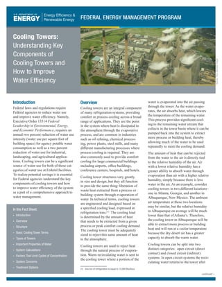
  • 1. Source:PaulJohnston-Knight Introduction Federal laws and regulations require Federal agencies to reduce water use and improve water efficiency. Namely, Executive Order 13514 Federal Leadership in Environmental, Energy, and Economic Performance, requires an annual two percent reduction of water use intensity (water use per square foot of building space) for agency potable water consumption as well as a two percent reduction of water use for industrial, landscaping, and agricultural applica- tions. Cooling towers can be a significant source of water use for both of these cat- egories of water use at Federal facilities. To realize potential savings it is essential for Federal agencies understand the key components of cooling towers and how to improve water efficiency of the system as a part of a comprehensive approach to water management. In this Fact Sheet: • Introduction • Overview • Structure • Basic Cooling Tower Terms • Types of Towers • Important Properties of Water • System Calculations • Factors That Limit Cycles of Concentration • System Concerns • Treatment Options Overview Cooling towers are an integral component of many refrigeration systems, providing comfort or process cooling across a broad range of applications. They are the point in the system where heat is dissipated to the atmosphere through the evaporative process, and are common in industries such as oil refining, chemical process- ing, power plants, steel mills, and many different manufacturing processes where process cooling is required. They are also commonly used to provide comfort cooling for large commercial buildings including airports, office buildings, conference centers, hospitals, and hotels. Cooling tower structures vary greatly in size and design, but they all function to provide the same thing: liberation of waste heat extracted from a process or building system through evaporation of water. In technical terms, cooling towers are engineered and designed based on a specified cooling load, expressed in refrigeration tons.(1) The cooling load is determined by the amount of heat that needs to be extracted from a given process or peak comfort cooling demand. The cooling tower must be adequately sized to reject this same amount of heat to the atmosphere. Cooling towers are used to reject heat through the natural process of evapora- tion. Warm recirculating water is sent to the cooling tower where a portion of the water is evaporated into the air passing through the tower. As the water evapo- rates, the air absorbs heat, which lowers the temperature of the remaining water. This process provides significant cool- ing to the remaining water stream that collects in the tower basin where it can be pumped back into the system to extract more process or building heat, thereby allowing much of the water to be used repeatedly to meet the cooling demand. The amount of heat that can be rejected from the water to the air is directly tied to the relative humidity of the air. Air with a lower relative humidity has a greater ability to absorb water through evaporation than air with a higher relative humidity, simply because there is less water in the air. As an example, consider cooling towers in two different locations– one in Atlanta, Georgia, and another in Albuquerque, New Mexico. The ambient air temperature at these two locations may be similar, but the relative humidity in Albuquerque on average will be much lower than that of Atlanta’s. Therefore, the cooling tower in Albuquerque will be able to extract more process or building heat and will run at a cooler temperature because the dry desert air has a greater capacity to absorb the warm water. Cooling towers can be split into two distinct categories: open circuit (direct contact) and closed circuit (indirect) systems. In open circuit systems the recir- culating water returns to the tower after (1) One ton of refrigeration is equal to 12,000 Btu/hour. continued > Cooling Towers: Understanding Key Components of Cooling Towers and How to Improve Water Efficiency FEDERAL ENERGY MANAGEMENT PROGRAM
  • 2. gathering heat and is distributed across the tower where the water is in direct contact with the atmosphere as it recircu- lates across the tower structure. Closed circuit systems differ in that the return fluid (often water, or sometimes water mixed with glycol) circulates through the tower structure in a coil, while cooling tower water recirculates only in the tower structure itself (see Figure 1). In this case, the return fluid is not exposed directly to the air. Structure Cooling towers are the primary com- ponent used to exhaust heat in open recirculating cooling systems. They are designed to maximize air and water contact to provide as much evaporation as possible. This is accomplished by maximizing the surface area of the water as it flows over and down through the tower structure. Figure 2 illustrates the different components of a cooling tower structure. First, the water is distributed evenly across the top of the cooling tower structure. Tower distribution decks can be a series of spray nozzles oriented up or down (like a landscaping sprinkler system) to uniformly distribute the water over the tower structure. In some cases, the distribution deck may just be a series of holes through which the water falls onto the tower structure. Regardless the distribution deck must uniformly apportion the recirculating water across the tower structure. Broken nozzles or plugged orifices will impede uniform distribution across the tower structure, negatively impacting the overall heat exchange capacity of the system. As the water falls from the distribution deck, the surface area is further expanded in the fill section. Older tower systems may feature splash bars made of plastic, fiberglass, or wood that serve to break the falling water into tiny droplets. In recent years, many different forms of labyrinth- like packing or film fill have been incorporated. The closely packed nature of film fill causes the water to travel through this portion of the tower in thin streams, improving thermal efficiency and the evaporation rate, thereby increas- ing heat rejection (see Figure 3). There are several variations of film fill geometries commercially available, and though they do greatly increase the heat rejection rate over splash-type fills, they are also much more susceptible to fouling, scaling, and microbiological growth (these are discussed in greater detail in the System Concerns section). Development of any of these problems greatly reduces the cooling efficiency and in severe cases can collapse portions of the tower fill or tower structure. To avoid this, film fill should be inspected routinely to ensure it is clean and free of debris, scale, and biological activity. To minimize losses due to drift and help direct airflow into the tower, louvers and drift eliminators are commonly used. Louvers are most often seen along the sides of the tower structure, while drift eliminators reside in the top section of the tower to capture entrained water droplets that may otherwise leave through the stack. Damaged or incorrectly oriented louvers along with damaged drift elimi- nators will lead to excessive losses due to drift from the tower structure. Therefore, louvers and drift eliminator sections should be routinely inspected and repaired to ensure optimal water usage. After the water passes through the fill it cascades down to a collection basin at the base of the tower structure. From the basin the cold water can be pumped back into the system to extract process or comfort cooling needs and begin the cycle all over again. By design, cooling towers consume large volumes of water through the evapora- tion process to maintain comfort cooling or process cooling needs, although they use significantly less water than similar capacity once-through cooling systems. Because the evaporative loss is water containing little to no dissolved solids, the water remaining in the cooling tower becomes concentrated with dissolved solids, which can lead to scaling and corrosive conditions. To combat these problems, water with high total dissolved solid content must be drained from the system via “blowdown.” The associated losses caused by blowdown, evaporation, drift, and system leaks must be accounted for by system make-up requirements. Figure 4 illustrates these water system flow locations in generic terms. Figure 1. Example of a Closed Circuit Cooling Tower. Figure 2. Overview of Cooling Tower Structure Components. Figure 3. Relative Thermal Performance of Different Types of Fill. continued > 2 FEDERAL ENERGY MANAGEMENT PROGRAM
  • 3. Basic Cooling Tower Terms Blowdown – Water discharged to remove high mineral content system water, impurities, and sediment. Cycles of Concentration – Technical term used to describe the mass flow rela- tionship between the amount of system feed water and the amount of blowdown sent down the drain. Also referred to as concentration ratio, cycles of concentra- tion correlates to the effective use of water in your system to provide heating or cooling needs. High cycles of concen- tration are directly related to low levels of water loss from your system. Dissolved Solids – The amount of dis- solved minerals present in the water. Drift – Droplets of water entrained in the air leaving the top of the tower, or blown from the side of the tower by crosswinds. Make-up – Water supply needed to replace all losses due to evaporation, leaks, or discharge in cooling systems. Types of Towers Cooling Towers – Cooling towers are classified by the direction of air flow (counter-flow or cross-flow) and the type of draft (mechanical or natural). Mechanical Draft Towers – Mechanical draft towers have air forced through the structure by a fan. The air flow can be pushed through by fans located at the base of the tower (referred to as forced draft), or pulled through by fans located at the top of the tower (referred to as induced draft). Induced draft towers tend to be larger than forced draft units. Natural Draft Towers – Natural draft towers are designed to move air up through the structure naturally without the use of fans. They use the natural law of differing densities between the ambient air and warm air in the tower. The warm air will rise within the chimney structure because of its lower density drawing cool ambient air in the bottom portion. Often times these towers are very tall to induce adequate air flow, and have a unique shape giving them the name “hyperbolic” towers (see Figure 5). Cross-Flow Towers – Cross-flow cooling towers are structured so that air flows horizontally across the falling water (see Figure 6). This design provides less resistance for the air flow, thereby reduc- ing the fan horsepower required to meet the cooling demand. These towers usually feature gravity-fed water distribution decks that are either open and uncovered, or that are covered to limit algae growth and debris from getting into the distribu- tion deck. Gravity-fed distribution decks have evenly spaced openings that the water drops through to be spread across the tower fill. Counter-flow Towers – Counter-flow cooling towers have upward air flow that directly opposes the downward flow of the water providing very good thermal efficiency because the coolest air contacts the coolest water (in the bottom section of the tower structure). Important Properties of Water A primary consideration for the operation of the cooling tower system is the water quality of the make-up source. Differing sources present differing challenges. Surface water sources include lakes, rivers, and streams, while groundwater sources consist of wells or aquifers. Depending on the location, surface water sources will have seasonal variations and can carry high levels of suspended silt and debris that cause fouling if not removed by pre-filtration systems. Groundwater sources don’t have the seasonal variations that surface water sources have, but depending on the geology of the region, they can have high levels of dissolved minerals that contrib- ute to scale formation or corrosion in the Figure 4. Illustration of Water Flow Across a Cooling Tower. Figure 5. Hyperbolic Cooling Towers (Source: Victor Vizu). Figure 6. Example Cross-flow Cooling Tower. continued > FEDERAL ENERGY MANAGEMENT PROGRAM 3
  • 4. cooling system. Recently, water reuse has become popular and many cooling systems are being supplied reclaimed effluent or discharge water from other processes. While water reuse is a wise resource option, consideration should be made regarding the quality of the water and how that will impact the efficient operation of the cooling system, and the system’s ability to meet the required cooling demand. Whether the source water is surface, ground, or reuse, in nature there are a few basic water quality considerations that should be understood. pH – pH is a measurement of how acidic or how alkaline a substance is on a scale of 0 to 14. A pH of 7.0 is neutral (the concentration of hydrogen ions is equal to the concentration of hydroxide ions), while measurements below 7.0 indicate acidic conditions, and measurements above 7.0 indicate basic or alkaline conditions. The pH scale is logarithmic (each incremental change corresponds to a ten-fold change in the concentration of hydrogen ions), so a pH of 4.0 is ten times more acidic than a pH of 5.0 and one hundred times more acidic than a pH of 6.0. Similarly, a pH of 9.0 is ten times more basic or alkaline than a pH of 8.0 and one hundred times more alkaline than a pH of 7.0. Hardness – Hardness refers to the pres- ence of dissolved calcium and magne- sium in the water. These two minerals are particularly troublesome in heat exchange applications because they are inversely soluble – meaning they come out of solu- tion at elevated temperatures and remain soluble at cooler temperatures. For this reason calcium and magnesium-related deposits will be evident in the warmest areas of any cooling system, such as the tubes or plates of heat exchangers, or in the warm top regions of the cooling tower fill where most of the evaporation occurs. Alkalinity – Alkalinity is the presence of acid neutralizing, or acid buffering minerals, in the water. Primary contribu- tors to alkalinity are carbonate (CO3 -2 ), bicarbonate (HCO3 - ), and hydroxide (OH- ). Additional alkaline components may include phosphate (PO4 -3 ), ammonia (NH3 ), and silica (SiO2 ), though contributions from these ions are usually relatively small. Conductivity – Conductivity is a mea- surement of the water’s ability to conduct electricity. It is a relative indication of the total dissolved mineral content of the water as higher conductivity levels cor- relate to more dissolved salts in solution. Conversely, purified water has very little dissolved minerals present meaning the conductivity will be very low. System Calculations To properly operate and maintain a cooling tower, there needs to be a basic understanding of the system water’s use. Water use of the cooling tower is the relationship between make-up, evapora- tion, and blowdown rates. There are a couple simple mathematical relationships between the blowdown rate, evaporation rate, make-up rate, and cycles of concen- tration of a cooling tower that are very useful to understand the principal flow rates. The first relationship illustrates the overall mass balance consideration around a given cooling tower: (1) Make-up = Blowdown+ Evaporation In this case, the blowdown accounts for all system losses including leaks and drift, except for evaporation. The second principal relationship defines cycles of concentration in terms of make- up flow and blowdown flow: (2) Cycles of Concentration = Make-up ÷ Blowdown This equation can be rearranged to either of the following to solve for the make-up rate or blowdown rate: (3) Blowdown = Make-up ÷ Cycles of Concentration (4) Make-up = Cycles of Concentration × Blowdown If the evaporation rate and cycles of concentration are known, the blowdown rate can then be determined by substitut- ing equation 4 into equation 1: (5) Cycles of Concentration × Blowdown = Blowdown + Evaporation Solving for blowdown: (6) Blowdown = Evaporation ÷ (Cycles of Concentration -1) Also, if the blowdown rate and cycles of concentration are known, the make-up rate can be determined by solving equa- tion 4, and then the evaporation rate can be determined by solving equation 6 for evaporation: (7) Evaporation = Blowdown × (Cycles of Concentration – 1) Factors That Limit Cycles of Concentration Increasing cycles of concentration saves water because it essentially means that water is being recirculated longer through the system before being blown down. But as levels of dissolved minerals elevate with higher cycles of concentration, scal- ing and corrosion potential also increase. All dissolved minerals have a saturation limit that, if exceeded, will lead to scale formation.(2) Additionally, high levels of dissolved minerals (high cycles of con- centration) increases the water’s tendency to be corrosive (corrosion is discussed in greater detail below). Chemical and mechanical treatment programs allow the thresholds of scaling tendencies and corrosion to be pushed; however, limits still persist necessitating management of dissolved minerals (conductivity) levels through elimination of high mineral content water through blowdown. The following section discusses these concerns in greater detail. System Concerns Cooling towers are dynamic systems because of the nature of their operation and the environment they function within. Tower systems sit outside, open to the elements, which makes them susceptible to dirt and debris carried by the wind. Their structure is also popular for birds and bugs to live in or around, because (2) Scaling will occur predominantly in the heat exchangers and in the fill-section of the tower structure, but may also occur in the piping or on the tower distribution deck. continued > 4 FEDERAL ENERGY MANAGEMENT PROGRAM
  • 5. of the warm, wet environment. These factors present a wide range of opera- tional concerns that must be understood and managed to ensure optimal thermal performance and asset reliability. Below is a brief discussion on the four pri- mary cooling system treatment concerns encountered in most open-recirculating cooling systems. Corrosion – Corrosion is an electro- chemical or chemical process that leads to the destruction of the system metal- lurgy. Figure 7 illustrates the nature of a corrosion cell that may be encountered throughout the cooling system metal- lurgy. Metal is lost at the anode(3) and deposited at the cathode.(4) The process is enhanced by elevated dissolved mineral content in the water and the presence of oxygen, both of which are typical of most cooling tower systems. There are different types of corrosion encountered in cooling tower systems including pitting, galvanic, microbiologi- cally influenced (Figure 8), and erosion corrosion, among others (expanded discussion is available at www.gewater. com/handbook/cooling_water_systems/ ch_24_corrosion.jsp). Loss of system metallurgy, if pervasive enough, can result in failed heat exchangers, piping, or portions of the cooling tower itself. Scaling – Scaling is the precipitation of dissolved minerals components that have become saturated in solution. Figure 9 illustrates calcium carbonate scale collecting on a faucet head. Factors that contribute to scaling tendencies include water quality, pH, and temperature. Scale formation reduces the heat exchange abil- ity of the system because of the insulating properties of scale, making the entire system work harder to meet the cooling demand. An expanded discussion for scaling is available at www.gewater. com/handbook/cooling_water_systems/ ch_25_deposit.jsp. Fouling – Fouling occurs when sus- pended particles fall out of solution forming deposits. Common foulants include organic matter, process oils, and silt (fine dirt particles that blow into the tower system, or enter in the make-up water supply). Factors that lead to fouling are low water velocities(5) , corrosion, and process leaks. Fouling deposits, similar to scale deposits, impede the heat exchange capabilities of the system by providing an insulating barrier to the system metal- lurgy. Fouling in the tower fill can plug film fill reducing the evaporative surface area, leading to lower thermal efficiency of the system. Microbiological Activity – Microbiological activity is micro- organisms that live and grow in the cool- ing tower and cooling system. Cooling towers present the perfect environment for biological activity due to the warm, moist environment. There are two distinct categories of biological activity in the tower system. The first being plank- tonic, which is bioactivity suspended, or floating in solution. The other is sessile biogrowth, which is the category given to all biological activity, biofilms, or biofouling that stick to a surface in the cooling system. Biofilms are problematic for multiple reasons. They have strong insulating properties, they contribute to fouling and corrosion, and the bi- products they create that contribute to further micro-biological activity. They can be found in and around the tower structure, or they can be found in chiller bundles, on heat exchangers surfaces, (see Figure 10), and in the system piping. Additionally, biofilms and algae mats are problematic because they are difficult to kill. Careful monitoring of biocide treatments, along with routine measure- ments of biological activity are important to ensure bio-activity is controlled and limited throughout the cooling system.(6) (3) The anode in a corrosion cell is defined as the site where metal is lost from the system structure and goes into solution. (4) The cathode in a corrosion cell is defined as the site where the metal lost at the anode is deposited. (5) Low water velocities may occur in poorly designed or improperly operated heat exchangers, in the cooling system piping, or in locations across the tower fill where uniform distribution is not maintained. (6) Beyond the operational and mechanical problems bioactivity causes in cooling tower systems, there is a human health issue if the system develops a specific bacterium known as Legionella. For more information regarding Legionella and Legionnaires’ disease go to www.cdc.gov/legionella/patient_facts.htm. Figure 7. Example of a Corrosion Cell. Figure 8. Microbiologically Influenced Corrosion (Source: Taprogge GmbH). Figure 9. Calcium Carbonate Scale (Source: Hustvedt). Figure 10. Biofouled Heat Exchanger (Source: Taprogge GmbH). continued > FEDERAL ENERGY MANAGEMENT PROGRAM 5
  • 6. Treatment Options Traditional water treatment programs are designed and implemented to account for the system concerns outlined above. This ensures the tower system operates optimally and achieves the needed cool- ing requirement. These programs consist of chemical additives including corrosion inhibitors, dispersants, scale inhibitors, and biocides that function to protect the cooling system and keep heat exchange surfaces clean and free of deposits or bio-films. When this is accomplished, maximum cycles of concentration can be achieved, and the cooling system can be operated at peak efficiency both in terms of water use and energy use. Beyond traditional water treatment programs there are options to build upon the current program, improve the current program, or replace the current program. Water Modeling – Software platforms provide the ability to model the system’s scaling tendencies, corrosion characteris- tics, and view optimal chemical applica- tion (also referred to as “dosing”). This can be a powerful tool to better understand if the system is operating at the maximum cycles of concentration possible, to see problem points in the sys- tem (low flow velocity, high temperature heat exchangers, for example), and to see impacts of varying water characteristics. Additionally, these modeling platforms allow a facility to review the potential impact of integrating water reuse resources, altering chemical treatment programs, or variations to certain opera- tional parameters such as pH set-point. In some cases, local and regional water treatment professionals may have the capability to supply similar modeling results as a part of your existing water treatment program or for a consulting fee. Green Chemistries – “Green” chemistry programs exist primarily to replace tradi- tional treatments that have been deemed harmful for environmental reasons. “Green” chemistries often don’t result in improved thermal efficiency or reduced water consumption, but provide environ- mental compliance and reduced dis- charge of harmful or illegal substances. Examples of “green” chemistry programs include polysilicate corrosion inhibitors (used for many years in potable water systems), polyaspartic acid dispersants, and hydrogen peroxide for biocide appli- cations. Another biocide that received the 1997 Environmental Protection Agency (EPA) Green Chemistry Award is THPS – tetrakis (hydroymethyl) phosphonium sulfate.(7) Automation – Automation systems are available providing a broad range of capacities to control single or multiple parameters in the cooling system such as conductivity and blowdown control, pH control, and real-time chemical monitor- ing and dosing. Blowdown controllers are available from several different commercial suppliers and offer a range of control points from simple conductivity/blowdown control, to timed or meter relay chemical dosing. Many of them incorporate water meter inputs and alarm relays if threshold measurements are exceeded. Blowdown controllers offer continuous monitoring and control of the blowdown of the tower system. This ensures high conductivity is avoided, minimizing scal- ing and corrosive conditions and mini- mizes excessive blowdown which wastes water. Figures 11 and 12 provide two opposing trends – one showing manual blowdown control and the other showing blowdown controlled with a conductivity controller. The charts illustrate the impact of implementing blowdown control- lers, revealing conductivity rates that stay much closer to the ideal set point compared to manual control. More robust automation platforms are also available from several manufacturers that provide system-wide monitoring and dosing. These platforms are scalable depending on the need, but offer conductivity/blowdown control, pH con- trol, real-time chemical monitoring and dosing, continuous corrosion monitoring, web-enabled reporting, and alarm relays. The benefit of these systems is tightened control of the various control points of the water treatment program, not only eliminating excessive water use and high cycle conditions, but also controlling chemical residuals and treatment dosing based on real-time corrosion and scaling indices. In trend terms, similar results to the conductivity improvements shown by Figures 11 and 12 can be achieved on chemical treatment residuals, pH set point and acid feed, biocide dosing, and corrosion monitoring. Figures 13 and 14 illustrate the performance improvement real-time dosing achieves on chemical residuals, ensuring the proper dosage of corrosion and scale inhibitors at all times and eliminating overfeed or underfeed of (7) To view the details of the THPS Green Chemistry Award go to www.epa.gov/gcc/pubs/pgcc/winners/dgca97.html. The complete list of recipients for the EPA’s Green Chemistry Awards is available at www.epa.gov/gcc/pubs/pgcc/past.html. Figure 11. Conductivity Trend for Manual or Timed Blowdown Control. continued > 6 FEDERAL ENERGY MANAGEMENT PROGRAM
  • 7. these products. These platforms offer web-enabled reporting interfaces so operators and maintenance staff can view tower performance remotely. Additionally, alarms for out-of- compliance measurements can be sent via email or text message alerting maintenance or operations personnel so corrective actions can be taken. Filtration – Filter systems are nothing new to industrial water systems, and have been used as pre-treatment in many different applications for many years. In recent years, side-stream filtration systems have become popular among many water treatment professionals. They function to remove suspended solids, organics, and silt particles down to 0.45 microns from a portion or all of the system water on a continual basis, thereby reducing fouling, scaling and microbiological activity. This allows the cooling system to work more efficiently and often reduces the amount of water blown down. However, the net impact on water consumption must consider the fact that these platforms require back-washing to clean the filter system. The amount of water used to regenerate the filter system should be added to the water lost due to evaporation and blowdown. Softening – Softeners function to remove hardness (calcium and magnesium) from the make-up water, or can be incorpo- rated as a side-stream system to soften a portion of the water continuously. This effectively manages (or eliminates) the amount of calcium and magnesium in the tower bulk water, thereby reducing the scaling potential of calcium and magnesium related deposits. By reducing or eliminating the scaling potential of calcium and magnesium, higher attention should be given to corrosion monitoring and the corrosive characteristics of the water. Calcium and magnesium function naturally as corrosion inhibitors, so if they are minimized or removed from the water, the corrosive conditions will increase putting more importance on the corrosion management program and tighter requirements on pH and alkalinity control. Figure 12. Conductivity Trend for a System Using a Blowdown Controller. Figure 13. Chemical Residuals Trend for Timed Feed. Figure 14. Chemical Residuals with Real-Time Dosing. continued > FEDERAL ENERGY MANAGEMENT PROGRAM 7
  • 8. Chemical-free Platforms – In recent years many innovations have been made in systems that provide chemical-free treatment replacements to traditional treatment platforms. These include systems that are singular in their target treatment, such as ozone(8) and ultraviolet biocide systems. These systems are very effective disrupting and eliminat- ing biological activity in the treatment zone, are flexible across a broad pH range, have low operating costs, and no undesirable byproducts. These systems treat an isolated point in the system, so far-reaching parts of the cooling system may have bioactivity due to extended distances from the treatment application point. Additionally, sessile bioactivity in the system beyond the point treatment may not be affected by the ozone and ultraviolet treatments. There are also other types of compre- hensive chemical-free platforms and the market has evolved, offering many dif- ferent types of platforms, which currently have varying degrees of success in the commercial marketplace. Several have been available for many years, but the evolution of the differing technologies has allowed for many more platforms to be developed.(9) The exact mechanisms used to alter the water’s characteristics vary from platform to platform, includ- ing electromagnetic and hydrodynamic principles as point treatments to control scaling and corrosion along with micro- biological activity. Systems that employ electromagnetic principles feature a treat- ment zone where an electric field courses through the flow of the recirculating water creating a “seeding” mechanism for dissolved minerals, principally calcium carbonate (also known as calcite). The seeding process creates a location for other dissolved minerals to agglomerate, or come out of solution, and then be removed via in-line filtration systems that follow the treatment system. The pulses of electricity also behave to counter bioactivity by damaging cell walls of potential microbes that pass through the treatment zone. Corrosion is controlled naturally by these systems as they allow the water to run at elevated pH levels, or alkaline conditions. Similarly, systems employing hydro- dynamic cavitation impact the water’s characteristics to control scaling, corro- sion, and biological activity. Instead of imparting electromagnetic principles to accomplish these ends, hydrodynamic cavitation impacts the water mechani- cally by rapid changes in pressure and mechanical collision in the treatment zone. Again, scaling is controlled through the seeding mechanism of calcium carbonate (calcite) formation, which in turn collects any other dissolved minerals nearing their respective saturation points and removes them through in-line filtra- tion. Low pressure zones strip the passing water of CO2 , maintaining naturally alkaline conditions to control corrosion. Lastly, the cavitation process ruptures cell walls of microbes passing through the treatment zone, thereby managing bioactivity in the cooling systems. These systems and many others like them have case studies and testimonials posted to demonstrate successful replacement of standard treatment options, including energy savings and water efficiency gains. They offer the advantage of reduced or eliminated need for treatment chemicals and have had many successful installations with documented improve- ments. However, some installations have had difficulty depending on the water quality, especially where the natural ten- dencies of the source water lean toward corrosive conditions. Furthermore, point treatments may have some difficulty with systems that are extensive and have far reaching-pipe runs or heat exchangers that are a substantial distance from the treatment system itself. Water Reuse – Water reuse options vary depending on the nature of water uses from site to site along with a broad range of other considerations, including local and regional water reuse laws and the availability of an adequate reuse resource. The concept is relatively simple: take discharge water from one application, apply sufficient treatment to it if needed, and then use it as a make-up water resource for the cooling tower system. Two examples of reuse are collecting the condensation from air-handlers and then pumping them back to the tower system make-up, or implementing a reverse osmosis system on the cooling tower blowdown. The condensed water that collects in air handlers is an excellent resource of high quality make-up water for the tower system. Because it is con- densation, by nature it will be relatively pure, and therefore will not require much additional treatment to make it sufficient for using as tower make-up water.(10) These systems are not difficult to engi- neer, nor are they typically very capital intensive.(11) Reverse osmosis (RO) systems (similar to Figure 15) are common in many Figure 15. Desalination Plant Using Reverse Osmosis Technology (Source: James Grellier). (8) Ozone is a reactive form of oxygen that has strong oxidizing characteristics making it very effective at controlling microbiological activity. (9) This document features mechanisms of a few different available systems and is not intended to be a comprehensive overview of all commercially available chemical-free water treatment systems. (10) The purity of the water will increase its natural abilities as a solvent and stagnant water systems are ideal for bioactivity. Care should be taken when considering the materials of construction for the collection and distribution system and if needed a small amount of biocide may be needed to minimize bioactivity. Additionally, the corrosion program for the tower system will need to reviewed or modeled to ensure proper corrosion control steps are taken to protect system metallurgy. (11) For more information on condensate recovery systems a case study is available at www.femp.energy.gov/program/waterefficiency_csstudies.html. continued > 8 FEDERAL ENERGY MANAGEMENT PROGRAM
  • 9. applications including desalination, industrial pre-treatment platforms, and applications where the purity require- ments for water are very high. In the case of water reuse from a tower system, the blowdown water would be sent directly into an RO system, which would purify a portion of the water (the permeate flow) and concentrate the bulk of the dissolved minerals into a smaller waste stream (the concentrate flow) that would be discharged from the system. These systems can be difficult to operate correctly, and are expensive to purchase and operate. However, locations where water resources are limited or discharge permits prohibit excessive cooling tower blowdown, RO platforms are a consider- ation to minimize the overall losses from a cooling system. Where to Get More Information FEMP Water Efficiency: www.femp.energy.gov/program/ waterefficiency.html Cooling Technology Institute: www.cti.org/ American Society of Heating, Refrigeration, and Air-Conditioning Engineers: www.ashrae.org/ American Society of Mechanical Engineers: www.asme.org/ If questions remain, contact: Will Lintner Federal Energy Management Program (202) 586-3120 William.Lintner@ee.doe.gov Brian Boyd Pacific Northwest National Laboratory (509) 371-6724 Brian.Boyd@pnl.gov EERE Information Center 1-877-EERE-INFO (1-877-337-3463) www.eere.energy.gov/informationcenter Printed with a renewable-source ink on paper containing at least 50% wastepaper, including 10% post consumer waste. DOE/PNNL-SA-75820 • February 2011 FEDERAL ENERGY MANAGEMENT PROGRAM 9 Prepared and produced by Pacific Northwest National Laboratory (PNNL) on behalf of the U.S. DOE-Federal Energy Management Program