Et201 chapter3 sinusoidal steady state circuit analysis
1. 1
TOPIC 3 : SINUSOIDAL STEADY STATE CIRCUIT ANALYSIS
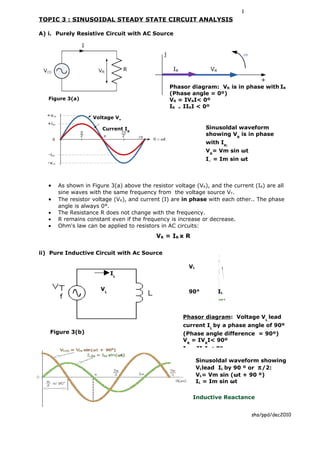
A) i. Purely Resistive Circuit with AC Source
Phasor diagram: VR is in phase with IR
(Phase angle = 0º)
Figure 3(a) VR = IVRI< 0º
IR = IIRI < 0º
Voltage VR
Current IR Sinusoldal waveform
showing VR is in phase
with IR:
VR= Vm sin ωt
IR = Im sin ωt
• As shown in Figure 3(a) above the resistor voltage (VR), and the current (IR) are all
sine waves with the same frequency from the voltage source VT.
• The resistor voltage (VR), and current (I) are in phase with each other.. The phase
angle is always 0°.
• The Resistance R does not change with the frequency.
• R remains constant even if the frequency is increase or decrease.
• Ohm's law can be applied to resistors in AC circuits:
VR = I R x R
ii) Pure Inductive Circuit with Ac Source
VL
IL
VL 90° IL
Phasor diagram: Voltage VL lead
current IL by a phase angle of 90º
Figure 3(b) (Phase angle difference = 90º)
VR = IVRI< 90º
IR =
IIRI < 0º
Sinusoldal waveform showing
VLlead IL by 90 º or π /2:
VL= Vm sin (ωt + 90 º)
IL = Im sin ωt
Inductive Reactance
shs/ppd/dec2010
2. 2
• Inductive reactance is the opposition to AC current flow in an inductive circuit,
• The symbol for inductive reactance is XL.Its unit is the ohm.
• Inductive reactance XL increase as the frequency across it increases,
• therefor inductive reactance is directly proportional to frequency,
• XL is given by the equation:
XL = 2πfL Ω
Since 2πf is equal to ω (the angular frequency),
XL = ωL Ω
• An inductor's current and voltage are related by an equation similar to Ohm's law:
VL= IL x XL
iii) Pure Capacitive Circuit with Ac Source
IC ω
90º VC
Phasor diagram: IC lead VC by 90 º or π /2:
(Phase angle = 90º)
Figure 3(c) VC = IVCI< 0º
IC = IICI <90º
Sinusoldal waveform showing IC lead VC by
90 º or π /2:
IC= Im sin (ωt + 90 º)
VC = Im sin ωt
Capacitive Reactance
• Capacitive Reactance in a purely capacitive circuit is the opposition to current flow
in AC circuits only.
• The symbol for capacitive reactance is XC.Its unit is the ohm.
• The capacitive reactance XC of the capacitor decreases as the frequency across it
increases.
• therefore capacitive reactance is inversely proportional to frequency
• XC is given by the equation:
XC= 1/2πfC Ω
Since 2πf is equal to ω (the angular frequency), XC = 1/ωC Ω
• A Capasitor current and voltage are related by an equation similar to Ohm's law:
Vc= IC x XC
iv) Graph showing relationship between R,XL and XC with respect to frequency
R shs/ppd/dec2010
frequency
3. 3
B) Series Circuit with inductive and capacitive load
• In a series circuit, current is taken as reference because current is the same in
series circuit.
i) R-L series
R XL
VR VL VL
+jVL
IR VR IL
IT
θ
VR IT
VAC , f
• When a sinusoidal voltage is applied to an RL circuit, the current and all the voltage
drops are also sine waves.
• Total current IT in an RL circuit always lags the source voltage VT
• The resistor voltage VR is always in phase with the current IT.
• In an ideal inductor, the voltage VL always leads the current IT by 90°.
• The impedance (Z) of an RL circuit is the total opposition to AC current flow caused by
the resistor (R) and the reactance of the inductor (XL).
• The equation for the total impedance (ZT) of an RL circuit is:
ZT
+jXL
or in complexs form : Z = R + j XL
Where: ZT = the total impedance in ohms
XL = the inductive reactance in ohms θ
R = the resistance in ohms R
• The total voltage in a series RL circuit is given by this equation:
Where:
Or in complex form : VT = VR + jV L VT = total voltage
VR = voltage across resistor R
• The total phase angle can be determined by the equation: voltage across inductor L
VL =
VL
θ = tan-1(XL/ R) or θ = tan-1 (VL/VR)
Complete Analysis of a Series RL Circuit:
Here is the procedure for doing a complete analysis of a series RL circuit, given the values of
θ R, L, f, and VT.
Step 1. Calculate the value of XL: XL = 2πfL
V CalculateT the total impedance:
Step 2. R I or in complex form Z= R + jXL
shs/ppd/dec2010
4. 4
Step 3. Use Ohm's Law to calculate the total current:
IT = V T / Z T
Step 4. Determine the currents through R and L. Since this is a series circuit:
IT = IL = IR (current is the same in series circuit)
Step 5. Calculate the voltages across R and L. By Ohm's Law:
VR = IT x R. and VL =IT x XL
Step 6. Determine the phase angles for R and L. Phase angles for these components in a
series circuit are always:
θR = 0º and
θL = 90º
Step 7. Calculate the total phase angle for the circuit:
θT = tan-1(XL/ R)
ii) R-C series
VR IT
-θ
VR IR IR
VC
_jVC
VT
VAC, f
• Total current IT in an RC circuit always lead the source voltage VT
• The resistor voltage VR is always in phase with the current IT.
• In capacitor, the voltage VC always lag the current IT by 90°.
• The impedance (Z) of an RC circuit is the total opposition to AC current flow caused by
the resistor (R) and the reactance of the capasitor (XC).
• The equation for the total impedance (ZT) of an RC circuit is:
R
θ
-jXC
or in complexs form : Z = R - j XC ZT
Where: ZT = the total impedance in ohms
XC = the capacitive reactance in ohms
R = the resistance in ohms
• The total voltage in a series RL circuit is given by this equation:
Where:
VT = total voltage
VR = voltage across resistor R
VC = voltage across capacitor C
Or in complex form : VT = VR - jV C
• The total phase angle can be determined by the equation:
θ = -tan-1(XC/ R) or θ = -tan-1 (VC/VR)
Complete Analysis of a Series RC Circuit
shs/ppd/dec2010
5. 5
Here is the procedure for doing a complete analysis of a series RC circuit, given the values of
R, C, f, and VT.
Step 1. Calculate the value of XC:
XC = 1 / (2πfC)
Step 2. Calculate the total impedance: or in complexs form Z= R – jXC
Step 3. Use Ohm's Law to calculate the total current:
IT = VT / ZT
Step 4. Calculate the currents through R and C. Since this is a series circuit:
IT = IC = IR
Step 5. Calculate the voltages across R and C. By Ohm's Law:
VR = IR x R and VC = IR x XC
Step 6. Determine the phase angles for R and C. Phase angles for these components are
always:
θR = 0º
θC = -90º
Step 7. Calculate the total phase angle for the RC circuit:
θT =- tan-1(XC/ R)
iii) Series R- L–C
• We have seen that the three basic passive components, R, L and C have very different
phase relationships to each other when connected to a sinusoidal AC supply. In a pure
ohmic resistor the voltage is "in-phase" with the current, in a pure inductance
the voltage "leads" the current by 90o, ( ELI ) and with a pure capacitance the
voltage "lags" the current by 90o, ( ICE ).
• This Phase Difference, Φ depends upon the reactive value of the components being
used and we know that reactance, ( X ) is zero if the element is resistive, positive if
the element is inductive and negative if the element is capacitive giving the resulting
impedance values as:
o ZR = R = R <0º
o ZL = jωL = ωL<90
o ZC = 1 = 1 <-90º
jωC ωC +jXL
R L C
R
VR IR jVL R
R -JXC
-jXC
Complete Analysis of a Series R-L-C Circuit
Here is the procedure for doing a complete analysis of a series R-L-C circuit, given the values
of R, C, L f, and VT.
Step 1. Calculate the value of XC and XL :
XC = 1 / (2πfC) and XL = 2πfL
Step 2. Calculate the total impedance:
ZT = R + jXL -jXC
Step 3. Use Ohm's Law to calculate the total current:
shs/ppd/dec2010
6. 6
IT = V T / Z T
Step 4. Calculate the currents through R, L and C. Since this is a series circuit:
IT = IC = IL =IR
Step 5. Calculate the voltages across R, L and C. By Ohm's Law:
VR = I T x R , VC = IT x XC and VL = IT x XL
Step 6 Prove that supply voltage in a series circuit is equivalent to the total vector of
voltages across each component of R, L and C. (Kirchoff’s Law)
VT = VR + jVL -jVC
Step 7. Calculate the total phase angle for the R-L-C series circuit:
θT = - tan-1(XC - XL/ R) if XC > XL
θT = tan-1(XL- XC/ R) if XL > XC
Phasor diagram for R-L-C series
+jXL
+jXL
ZT R
+j(XL-XC)
-θ
θ
-j(XC-XL) ZT
R
-jXC
XL > XC (the circuit is inductive) XC > XL (the circuit is capacitive)
C) Parallel Circuit with inductive and capacitive load
• In a parallel circuit, voltage is taken as reference because voltage is the same in
parallel circuit
i) R-L parallel
IR VT
IT IR IL
-θ
VR VL
VT, f
R XL -jIL
IT
Complete Analysis of a Parallel RL Circuit
Here is the procedure for doing a complete analysis of a parallel RL circuit, given the values of
R, L, f, and VT.
Step 1. Calculate the value of XL and
XL = 2π fL or jω L
Step 2. Determine the voltages for R and L. Since this is a parallal circuit:
VT = VL = VR
Step 3. Use Ohm's Law to calculate the currents for R and L:
IR = V T / R and I L = VT / X L
shs/ppd/dec2010
7. 7
Step 4. Calculate the total current:
or in complexs form ; IT = IR - jIL
Step 5. Use Ohm's Law to calculate the total impedance:
ZT = VT / IT
Step 6. Determine the phase angles for R and L. Phase angles for these components in a
parallel circuit are always:
θR = 0º and θL = -90º
Step 7. Calculate the total phase angle for the circuit:
θT = -tan-1(IL/ IR)
Total Impedance(ZT) for Parallel RL Circuits
A simple parallel RL circuit is one that look like the one
shown here --
Total Impedance ZT = R x (jXL)
R + jXL
Or Total Impedance 1/ZT = √(1/R)2 +(1/XL)2
ii) R-C parallel
IT
+jIC
IT
IT IC
R VC θ
VR IR VT
C
Complete Analysis of a Parallel RC Circuit
Here is the procedure for doing a complete analysis of a parallel RC circuit, given the values of
R, C, f, and VT.
Step 1. Calculate the value of XC: XC = 1/(2π fL)
Step 2. Determine the voltages for R and L. Since this is a parallal circuit:
VT = V L = V R
Step 3. Use Ohm's Law to calculate the currents for R and L:
IR = V T / R and I C = VT / X C
Step 4. Calculate the total current:
or in complexs form ; IT = IR + jIC
Step 5. Use Ohm's Law to calculate the total impedance:
ZT = VT / IT
Step 6. Determine the phase angles for R and L. Phase angles for these components in a
parallel circuit are always:
θR = 0º and θC = 90º
Step 7. Calculate the total phase angle for the circuit:
θT = tan-1(IC / IR)
shs/ppd/dec2010
8. 8
Total Impedance 1/ZT = √(1/R)2 +(1/XC)2
or Total Impedance ZT = R x (- jXC)
R +(– jXC)
iii) Parallel R-L-C
jIC
IS
IR IL IC
VR VL VC
R L C IR VT
jIL
Complete Analysis of a Parallel R-L-C Circuit
Here is the procedure for doing a complete analysis of a parallel RLC circuit, given the values
of R, L, C, f, and VT.
Step 1. Calculate the value of XL and XC:
XL = 2πfL Ω XC = 1/(2π fL) Ω
Step 2. Determine the voltages for R , L and C. Since this is a parallal circuit:
VT = V L = V C = V R
Step 3. Use Ohm's Law to calculate the currents for R and L:
IR = V T / R , IL = VT / XL and I C = VT / X C
Step 4. Calculate the total current:
or in complexs form ; IT = IR + jIC + (-jIL)
Step 5. Use Ohm's Law to calculate the total impedance:
ZT = VT / IT
Step 6. Determine the phase angles for R and L. Phase angles for these components in a
parallel circuit are always:
θR = 0º , θC = 90º and θL = -90º
Step 7. Calculate the total phase angle for the circuit:
θT = tan-1 (IC – IL) / IR
Total Impedance :
XC
1/ZT = √(1/R)2 +(1/XL – 1/XC)2
jIC
jIC
Phasor diagram for R-L-C parallel
j(IC-IL)
shs/ppd/dec2010
IR V - j(IL-IC)
-jIL -jIL
9. 9
IT IR V
-θ
θ
IC> IL IL > I C
iv) Impedance Triangle
The opposition to current flow in AC series circuits is impedance, Z which has two
components, resistance R and reactance, X and from this we can construct an impedance
triangle.,
D) Combination of series- parallel R-L-C circuits.
Z2
I2
Z1
IT
V2
V3
V1 I3
Z3
VT, f
• Components connected in series must have the same current.
• Components connected in parallel must have the same voltage
• These two rules apply not only to individual components but also to portions of
circuits.
i) Total impedance in a series-parallel circuit.
ZT = Z1 + Z2 // Z3
ZT =Z1 + Z2 X Z3
Z2 + Z3
shs/ppd/dec2010
10. 10
ii) Total current: IT = VT/ZT and I2 =V2/Z2
I3 = V3/Z3
Supply current, IT will be the vector sum of the branch currents I2 and I3 (KCL)
iii) The voltage drop across each resistor in a series-parallel circuit.
V2 = V3 (Z2 parallel to Z3 so the voltage drop is the same)
Supply Voltage VT will be the vector sum of V1 and V2 or V1 and V3 (KVL)
V1 = IT x Z1
V2 = V3 is the vector of VT minus V1
or V2=V3= IT x Z2xZ3
Z2 +Z3
E) i) Work and Energy
• In physics, work is the expenditure of energy to overcome a restraint or to achieve a
change in the physical state of a body.
• Energy is the ability to do work.
• Energy comes in many forms. A few of these are:
o heat energy
o light energy
o sound energy
o mechanical energy
o chemical energy
o electrical energy.
• Many everyday devices convert energy from one form to another. For example:
o A loudspeaker converts electrical energy to sound energy.
o A toaster converts electrical energy to heat energy.
o A light bulb or LED converts electrical energy to light energy.
• Energy(E) is measured in units called joules, symbol J to stand for the joule.
ii) Power
• Power, abbreviated P, is the rate at which energy is spent.
• In other words, power is the amount of energy that's used in a given amount of time,
or energy per time. In equation form, that's
P=E/t joules per second or WATT (W)
Power Formulas
• When current flows through resistance, electric energy is converted to heat energy.
• The rate of this energy conversion is the power.
• P = I2 × R
P=I×V
P = V2 / R
• In each of these equations, R is the size (in ohms) of the resistance, V is the voltage
(in volts) across the resistance, and I is the current (in amps) through the resistance.
F) Power consumption in AC circuits
i) Power in Pure Resistive
• True or Actual power,. symbol Ptrue unit Watt (W) is a measure of the rate at which a
component or circuit loses energy. This energy loss is usually due to dissipation of heat
shs/ppd/dec2010
11. 11
(as in a resistor) or conversion to some other form of energy (as in a motor that
converts electrical energy to motion).
• In a resistive circuit : Current and Voltage waveforms are in phase,
Average power: P = IRMS x ERMS
POWER P
• In AC circuits, the resistor's voltage and current must be in rms values
(effective values):
Ptrue = Irms2 x R
Ptrue = Vrms2 / R
Ptrue = Vrms x Irms
• Power dissipation in a resistor means that the resistor is converting some of the
circuit's electrical energy to heat energy. This energy is lost from the circuit as the air
around the resistor is heated. This is True Power
ii) Pure capacitance and inductance
a) Power in an Inductor
• An inductor stores energy in its magnectic field when there is current through it.
• An ideal inductor (assuming no winding resistance) does not dissipate energy, it only
stores it.
• When an AC voltage is applied to an ideal inductor, energy is stored by the inductor
during a portion of a cycle, then the stored energy is returned to the source during
another portion of the cycle.
• Ideally all of the energy stored by an inductor during the positive portion of the power
cycle is returned to the source during the negative portion
• No net energy is lost in an ideal inductor due to conversion of heat.
• So the True power (Ptrue), unit watt is zero.
• The rate at which an inductor stores or returns energy is called its Reactive
power(Q), unit VAR (volt ampere reactive).
• These formulas apply:
Q = Vrms x Irms
Q = V2 rms/XL
Q = I2 rms x XL
Power P
vL = Vmax sin (ωt+ 90º)
iL = Imax sin ωt
VL lead IL by 90º
P = I V = 0 watt (because +cycle =-cycle so
average power =0)
0 - 90º 90º –180º 180º -270º 270º - 360º
VL= +. VL= - VL= - VL= +
IL= + IL= + IL= - IL= -
shs/ppd/dec2010
12. 12
b) Power in a Capaciotr
• In capacitor, true power is zero, capacitors don't lose any energy as heat.
• Reactive power is a measure of the rate at which a component is storing energy or
returning energy to the circuit.
• symbol Q for reactive power, unit called the VAR. (volt-ampere reactive)
• These formulas apply:
Q = Vrms x Irms
Q = Vrms2 / XC
Q = Irms2 x XC
Question: Suppose a 1 µF capacitor has a voltage drop of 3 V rms, and the voltage's
frequency is 2 kHz. Calculate the capacitor's reactive power.
• For sinusoidal waves, the current through a capacitor leads the voltage across it by 90º,
as shown in this example below.
Power P
vc = Vmax sin ωt
iC = Imax sin (ωt + 90º)
Ic lead VC by 90º
P = I V = 0 watt (because +cycle =-cycle so
average power (True Power) =0)
0 - 90º 90º –180º 180º -270º 270º - 360º
90º Vc= +. V C= + VC= - IC = +
I C= + I C= - Ic = - VC= -
Reactive Power
• Reactive power (Q) is the power consumed
in an AC circuit because of the expansion
and collapse of magnetic (inductive) and
electrostatic (capacitive) fields.
• Reactive power is expressed in volt-
amperes-reactive (VAR).
• Unlike true power, reactive power is not useful power because it is stored in the circuit
itself.
Total Power (apparent power)
• The total power delivered by the source is the apparent power.
• Apparent power is expressed in volt-amperes (VA).
• Part of this apparent power,called true power, is dissipated by the circuit resistance in
the form of heat.
• The rest of the apparent power is returned to the source by the circuit inductance and
capacitance
• The phasor combination of resistive power (true power) and reactive power is the
apparent power.
Power Triangle
shs/ppd/dec2010
13. 13
• In an RL and RC circuit, part of the power is resistive and part reactive.
Power Factor
• Power factor (pf) is the ratio between true power and apparent power. True power is
the power consumed by an AC circuit, and reactive power is the power that is stored in
an AC circuit.
• Cos Φ is called the power factor (pf) of an AC circuit. where Φ is the phase angle
between the applied voltage and current sine waves and also between P and S on a
power triangle (Refer power triangle)
• The power factor (pf=cos Φ) indicates how much of the apparent power is true power.
• A power factor of 1 indicates a purely resistive circuit, and a power factor of 0
indicates a purely reactive circuit.
• Power Factor (pf) = Cos Φ= P/S = Watt/VA.
where
cos Φ = power factor (pf)
P = true power (watts)
S = apparent power (VA)
• In an inductive circuit, the current lags the voltage and is said to have a lagging power
factor
• In a capacitive circuit, the current leads the voltage and is said to have a leading
power factor
Power Factor Correction
• In an electric power system, a load with a low power factor draws more current
than a load with a high power factor for the same amount of useful power
transferred.
• The higher currents increase the energy lost in the distribution system, and require
larger wires and other equipment.
• Because of the costs of larger equipment and wasted energy, electrical utilities will
usually charge a higher cost to industrial or commercial customers where there is a
low power factor.
• Linear loads with low power factor (such as induction motors) can be corrected with a
passive network of capacitors or inductors.
• Power factor correction brings the power factor of an AC power circuit closer
to 1 by supplying reactive power of opposite sign, adding capacitors or inductors
which act to cancel the inductive or capacitive effects of the load.
Questions
1. A series circuit with resistance 100Ω and capacitance 50µF connected to a voltage
supply of 200V, 50 Hz. Calculate:
a) the circuit impedance
b) total circuit current
c) power factor of the circuit
d) the phase nagle between the total voltage and the line current
e) voltage across resistor
f) voltage across capacitor
g) draw the related vector diagram for the circuit,
2. A pure inductor 0,08Henry is in series with a resistor 15Ω. The voltage supply is 240 V,
50 Hz, calculate:
a) the current in the circuit
shs/ppd/dec2010
14. 14
b) the power factor of the circuit
c) Voltage drop across R and L
d) The actual power ,
e) the reactive power and
f) the apparent power
g) draw the power triangle
2. A single phase motor of 50HZ, takes 30 kWatt and 20 kVAR from the supply of 240 V
Calculate the value of the capacitance needed to be connected parallel to the motor
for the correction of the power factor to be 0.95 lagging
shs/ppd/dec2010