1.
v 2.7
Satellite Antenna Design and
Systems Engineering Software
SATSOFT speeds the process of planning, de- user interface enables users with even a basic
signing, and marketing communication satellite knowledge of antennas to use the software pro-
payloads. Quickly assess antenna coverage ductively. Advanced tools will appeal to the an-
and gain, conduct antenna trade studies, de- tenna specialist. If you need software to model
velop shaped beam and multi-beam antenna satellite antennas for GEO, LEO or MEO con-
designs and complete many other tasks re- stellations, SATSOFT was written for you. Free
quired for payload design and regulatory filings. 30 day evaluations available at www.satsoft.
SATSOFT was written for the systems engineer com. See for yourself what SATSOFT can do
as well as the antenna specialist. Its graphical for you.
Please visit www.satsoft.com for the latest information
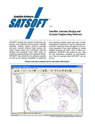
SATSOFT Composite View aggregates all objects in the scenario.
2. SATSOFT Highlights
Analyze Your Current System & Plan Your Next
SATSOFT provides essential tools for analyzing your current
satellite communications system and planning your next one.
Many tools are provided for designing and analyzing space-
based communications antenna systems. Basic features
include map and contour plotting, coordinate system conver-
sions, file import/export, boresight rotation, pointing boxes,
visibility contours, performance tables, and other features.
Context-sensitive help is available for dialog boxes, toolbar
Performance tables of gain, EIRP, G/T and other parameters buttons, menus and views.
can be prepared for cities and synthesis stations.
SATSOFT Complements Your Other Software
Windows clipboard support and extensive file import and
export capabilities lets you do more with SATSOFT. Copy
graphics to the clipboard for use with Microsoft Office pro-
grams. Import antenna patterns from other modeling programs
such as GRASP and POS. Load patterns from the ITU data-
base. File antenna patterns electronically with the ITU.
Simplified Antenna Pattern Synthesis
Complex algorithms simplify antenna beam-shaping exercises.
Select an antenna model and specify its parameters. Create a
coverage definition with the polygon editing tools and fill it with
component beams and synthesis stations using the automated
Shaped patterns can be synthesized using the integrated an-
tools provided. A single click of the mouse optimizes, com-
tenna models or imported component beam sets. putes and displays the pattern. Results are obtained in sec-
onds on Pentium II class hardware, even when high fidelity
models are being used, such as the optional SATSOFT/PO, a
physical optics reflector model.
Contour Plots of EIRP, G/T, C/I, and More
A fast contouring engine within SATSOFT produces plots
quickly and accurately. Intelligent auto-ranging and zoom-in/
zoom-out functions make it easy to view a desired range of
data. You can also create plots at a precise scale for overlay-
ing or for use when digitizing coverage areas and contours.
Conversion from directivity or gain to other parameters is
accomplished by specifying a dB offset. By applying slant-
range path-loss compensation, flux density contours can be
computed. SATSOFT will also plot copol/crosspol ratios for
Specification of antenna model parameters is simplified by vector antenna patterns.
smart dialog boxes that provide instant performance feedback.
Maps From Any Altitude or Viewpoint
SATSOFT transforms antenna contours, geopolitical maps,
coverage polygons, cities, and other features into any of nine
different display coordinate systems, simply by making the
desired choice. The four most commonly used antenna
coordinate systems are provided for pattern import and
display. Azimuth-Equidistant and Equirectangular (rectangular
lat, long) projections are also provided. The earth is modeled
as an oblate spheroid.
Interactive Antenna Boresight Rotation
Click and drag the antenna pattern to change its boresight, or
specify the boresight angles directly. Antenna boresight may
Contour type, levels, polarization, path-loss and other proper- also be pointed at a fixed position on the map.
ties can be specified quickly and easily.
3. SATSOFT Features
Automated Antenna Pattern Synthesis Performance Tables
Perform antenna trade studies using single beam, multi-beam, and Prepare tables of antenna performance at city and station locations.
shaped beam designs. Directivity, gain, EIRP, G/T, flux density, and other parameters can
Synthesize shaped patterns from one or more coverage polygons in be tabulated in spreadsheet format.
minutes. Single-click shaped pattern synthesis. Copy and paste tables into Excel and other applications, print, and
Automatic creation of component beam and synthesis station grids export to file.
from coverage polygons.
Full suite of graphical editing tools to add, delete, move, or change
File Import and Export Capabilities
parameters of beamlets and stations.
Import CPLAN work files.
Mini-max optimizer works with all antenna models and imported
component beam sets. Export performance tables in tab delimited format (for spreadsheet
import) via file or clipboard.
Show component and/or composite contours with a single click.
Export vector graphics in Windows enhanced metafile (EMF) format.
Create and edit tables of beamlet positions and polygon vertices.
Import scalar and vector antenna patterns defined in (u,v), (θ,φ),
Quickly trade performance with different antenna models, e.g.,
phased array vs. reflector (antenna models are optional). az/el, and el/az coordinate grids.
Import and export SATSOFT (CPLAN), GRASP, ACP4, Eutelsat,
and stk antenna pattern files. Regular & irregular grids (measured
Contour Plotting patterns) can be imported.
Plot contours of directivity, EIRP, G/T, C/I, & other parameters. Export synthesis station grids in SATSOFT (CPLAN) or TICRA's
Plot contours of copol/crosspol ratios for vector antenna patterns. POS4 formats.
Full control over which beams in a multi-beam design are plotted. Import and export antenna contours in SATSOFT, stk, shapefile, and
Specify and plot component and composite contours independently. ITU Graphics Exchange (GXT) format.
Specify contour levels, line styles, colors, font, etc. Fill contours. Export reflector geometry in TICRA's GRASP7 format.
Slant-range path-loss compensation enables computation of flux Import and export coverage polygons and map data in SATSOFT
density and carrier to thermal noise contours. (CPLAN), stk, shapefile, TICRA .pol and GXT formats.
Intelligent auto-ranging and zoom-in/zoom-out functions.
Create plots at a precise scale for overlaying or as an aid in digitizing Windows Clipboard Support
contours and polygons. Copy vector graphics to clipboard for import to Microsoft Office and
Whittaker/Shannon interpolation/reconstruction of antenna patterns other applications.
saves a significant amount of computer time and disk space by ena- Copy & paste antenna and polygon objects, city lists, performance
bling the use of coarse pattern grids. Reduces computation time of tables, beamlet locations, polygon vertices, and feed excitations.
high fidelity antenna models by an order of magnitude.
Miscellaneous
Coordinate Systems and Maps
GUI conforms to standard Windows user interface guidelines.
(u,v), (θ,φ), az/el, el/az, azimuth equidistant, orthographic, azimuth Context sensitive help for dialog boxes, toolbar buttons and menus.
equal-area, and equirectangular coordinate systems.
Tree view shows hierarchy of satellites, antennas, polygons, and
The earth is modeled as an oblate spheroid consistent with the facilitates copying & moving of these objects.
WGS84 geoid. DCW World map and city databases are provided.
Drag and drop work files, pattern files, coverage polygon, contour,
City database (MS Access format) of over 1600 of the largest cities and GXT files from Windows Explorer.
in the world connected via standard Windows ODBC drivers.
Dynamic memory throughout, so the number and size of antenna
Plot pointing box, city name and/or designator at each city location. patterns, contours, polygons, satellites, beamlets, and stations is
Elliptical and rectangular pointing boxes computed from spacecraft limited only by available memory and disk space.
roll, pitch, and yaw errors. Customizable toolbars.
Interactive boresight rotation. Click and drag the antenna pattern to
change its boresight.
Specify boresight in (az, el), (lon, lat), or in terms of 3 Euler angles. Antenna Models
Plot meridians and parallels. Consistent interface to all antenna models. Beam layout,
optimization, contouring, interpolation, etc, works the same for all
Mouse Coordinates Pane displays coordinates of the mouse in user
models.
selectable coordinate system.
A Gaussian Beam model is provided for modeling circular and
Plot a sin space unit circle in any coordinate system.
elliptical beams.
Plot a boresight marker.
Plot visibility (elevation) contours with control of thickness, line style,
color, and labeling. SATSOFT Professional (SATSOFT/PRO)
Plot Edge of Coverage (EOC) contours for a specified polygon.
Polygon Creation & Editing Tools Expand & contract polygons by the satellite pointing error.
Automatically expand coverage polygons by the satellite pointing
A full suite of editing functions is provided.
error during synthesis station generation.
Create and edit polygons with the mouse or any Windows compati-
Resample antenna patterns for a specified resolution & coordinate
ble digitizing tablet.
system, for example, (u,v), (az,el), (lat,lon)
Create and edit polygons from a table of coordinates.
Create shaped beams designed to service a coverage area from
Move, copy, rotate, delete, undelete, split, join, downsample func- multiple orbital slots.
tions. Change line style, color, label, thickness, etc. Fill polygons.
Prepare performance tables with pointing error degradation, pattern
Compute the solid angle subtended by the polygon and correspond- slope, crosspol C/I, and axial ratio.
ing maximum directivity, and polygon centroid.
Draw pointing error ellipse at polygon vertices.
Create grids of polygons with the grid creation tool.
Digitize existing antenna contours with any Windows compatible Multiple shaped beams can be synthesized simultaneously using
tablet. any antenna model or imported component beam file.