Home Made Hydraulic Ram Pump - Part 1

Home Made Hydraulic Ram Pump - Part 1 ` For more information, Please see websites below: ` Organic Edible Schoolyards & Gardening with Children = http://scribd.com/doc/239851214 ~ ` Double Food Production from your School Garden with Organic Tech = http://scribd.com/doc/239851079 ~ ` Free School Gardening Art Posters = http://scribd.com/doc/239851159 ~ ` Increase Food Production with Companion Planting in your School Garden = http://scribd.com/doc/239851159 ~ ` Healthy Foods Dramatically Improves Student Academic Success = http://scribd.com/doc/239851348 ~ ` City Chickens for your Organic School Garden = http://scribd.com/doc/239850440 ~ ` Huerto Ecológico, Tecnologías Sostenibles, Agricultura Organica http://scribd.com/doc/239850233 ` Simple Square Foot Gardening for Schools - Teacher Guide = http://scribd.com/doc/239851110 ~

Recommended
Recommended
More Related Content
What's hot
What's hot (20)
Viewers also liked
Viewers also liked (15)
Similar to Home Made Hydraulic Ram Pump - Part 1
Similar to Home Made Hydraulic Ram Pump - Part 1 (20)
More from School Vegetable Gardening - Victory Gardens
More from School Vegetable Gardening - Victory Gardens (20)
Recently uploaded
Recently uploaded (20)
Home Made Hydraulic Ram Pump - Part 1
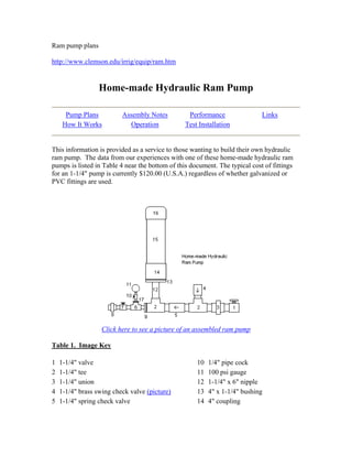
- 1. Ram pump plans http://www.clemson.edu/irrig/equip/ram.htm Home-made Hydraulic Ram Pump Pump Plans Assembly Notes Performance Links How It Works Operation Test Installation This information is provided as a service to those wanting to build their own hydraulic ram pump. The data from our experiences with one of these home-made hydraulic ram pumps is listed in Table 4 near the bottom of this document. The typical cost of fittings for an 1-1/4" pump is currently $120.00 (U.S.A.) regardless of whether galvanized or PVC fittings are used. Click here to see a picture of an assembled ram pump Table 1. Image Key 1 1-1/4" valve 10 1/4" pipe cock 2 1-1/4" tee 11 100 psi gauge 3 1-1/4" union 12 1-1/4" x 6" nipple 4 1-1/4" brass swing check valve (picture) 13 4" x 1-1/4" bushing 5 1-1/4" spring check valve 14 4" coupling
- 2. 6 3/4" tee 15 4" x 24" PR160 PVC pipe 7 3/4" valve 16 4" PVC glue cap 8 3/4" union 17 3/4" x 1/4" bushing 9 1-1/4" x 3/4" bushing All connectors between the fittings are threaded pipe nipples - usually 2" in length or shorter. This pump can be made from PVC fittings or galvanized steel. In either case, it is recommended that the 4" diameter fittings be PVC fittings to conserve weight. Conversion Note: 1" (1 inch) = 2.54 cm; 1 PSI (pound/square inch) = 6.895 KPa or 0.06895 bar; 1 gallon per minute = 3.78 liter per minute. PR160 PVC pipe is PVC pipe rated at 160 psi pressure. Click here to see an image-by-image explanation of how a hydraulic ram pump works Click here to see a short mpeg movie of an operating ram pump (Note - this is a 6.2 mb movie clip. On slower systems (11 mbps, etc.), it will load "piece-meal" the first time. Allow it to finish playing in this fashion, then press the play button again to see it in full motion with no "buffering" stops. Dial-up users may have to download the file to see it - simply right-click on the link, then select "Save Target As..." to save it to your computer. Downloading may take considerable time if you are on a slower dial-up system.) Assembly Notes: Pressure Chamber - A bicycle or "scooter tire" inner tube is placed inside the pressure chamber (part 15) as an "air bladder" to prevent water-logging or air-logging. Inflate the tube until it is "spongy" when squeezed, then insert it in the chamber. It should not be inflated very tightly, but have some "give" to it. Note that water will absorb air over time, so the inner tube is used to help prevent much of this absorbtion. You may find it necessary, however, to drain the ram pump occasionally to allow more air into the chamber. (The University of Warwick design (link below, pages 12-13) suggests the use of a "snifter" to allow air to be re-introduced to the ram during operation. Their design, however, is substantially different from the one offered here and provides a location (the branch of a tee) where the addition of a snifter is logical. This design does not. Also, correctly sizing the snifter valve (or hole as the case may be) can be problematical and may allow the addition of too much air, resulting in air in the drive pipe and ceasing of pumping operation. For these reasons we have elected not to include one in this design.) According to information provided by the University of Warwick (UK) ( http://www.eng.warwick.ac.uk/dtu/pubs/tr/lift/rptr12/tr12.pdf , page 14), the pressure chamber should have a minimum volume of 20 times the expected delivery flow per "cycle" of the pump, with 50 times the expected delivery being a better selection. The chart below provides some recommended minimum pressure chamber sizes based on 50
- 3. times the expected delivery flow per "cycle." Note that larger pressure chambers will have not have any negative impact on the pump performance (other than perhaps requiring a little more time to initially start the pump). Some of the lengths indicated are quite excessive, so you may prefer to use two or three pipes connected together in parallel to provide the required pressure chamber volume. Well pump pressure tanks will also work well - just make sure they have at least the minimum volume required. Table 2. Suggested Minimum Pressure Chamber Sizes (Based on ram pumps operating at 60 cycles per minute.) Length of Pipe Required for Pressure Chamber (for indicated pipe diameter) (lengths are in inches) Drive Pipe Diameter (inches) Expected Flow Per Cycle (gallons) Pressure Chamber Volume Required (gallons) 2 inch 2-1/2 inch 3 inch 4 inch 6 inch 8 inch 10 inch 12 inch 3/4 0.0042 0.21 15 11 7 -- -- -- -- -- 1 0.0125 0.63 45 32 21 -- -- -- -- -- 1-1/4 0.020 1.0 72 51 33 19 -- -- -- -- 1-1/2 0.030 1.5 105 74 48 27 -- -- -- -- 2 0.067 3.4 -- 170 110 62 27 16 -- -- 2-1/2 0.09 4.5 -- 230 148 85 37 22 14 -- 3 0.15 7.5 -- -- 245 140 61 36 23 16 4 0.30 15 -- -- -- 280 122 72 45 32 6 0.80 40 -- -- -- -- 325 190 122 85 8 1.60 80 -- -- -- -- -- 380 242 170 (Note - it is quite difficult to push a partially-inflated 16 inch bicycle inner tube into a 3 inch PVC pipe. Due to this we suggest the pressure chamber be a minimum of 3 inches in diameter.) A 4" threaded plug and 4" female adapter were originally used instead of the 4" glue-on cap shown in the image, This combination leaked regardless of how tightly it was tightened or how much teflon tape sealant was used, resulting in water-logging of the pressure chamber. This in turn dramatically increased the shock waves and could possibly have shortened pump life. If the bicycle tube should need to be serviced when using the glue cap design, the pipe may be cut in half then re-glued together using a coupling. Valve Operation Descriptions - Valve #1 is the drive water inlet for the pump. Union #8 is the exit point for the pressurized water. Swing check valve #4 is also known as the "impetus" or "waste" valve - the extra drive water exits here during operation. The
- 4. "impetus" valve is the valve that is operated manually at the beginning (by pushing it in with a finger) to charge the ram and start normal operation. Valves #1 and #7 could be ball valves instead of gate valves. Ball valves may withstand the shock waves of the pump better over a long period of time. The swing check valve (part 4 - also known as the impetus valve) can be adjusted to vary the length of stroke (please note that maximum flow and pressure head will be achieved with this valve positioned vertically, with the opening facing up). Turn the valve on the threads until the pin in the clapper hinge of the valve is in line with the pipe (instead of perpendicular to it). Then move the tee the valve is attached to slightly away from vertical, making sure the clapper hinge in the swing check is toward the top of the valve as you do this. The larger the angle from vertical, the shorter the stroke period (and the less potential pressure, since the water will not reach as high a velocity before shutting the valve). For maximum flow and pressure valve #4 should be in a vertical position (the outlet pointed straight up). Swing check valve #4 should always be brass (or some metal) and not plastic. Experiences with plastic or PVC swing check valves have shown that the "flapper" or "clapper" in these valves is very light weight and therefore closes much earlier than the "flapper" of a comparable brass swing check. This in turn would mean lower flow rates and lower pressure heads. The pipe cock (part 10) is in place to protect the gauge after the pump is started. It is turned off after the pump has been started and is operating normally. Turn it on if needed to check the outlet pressure, then turn it back off to protect the gauge. Drive Pipe - The length of the drive pipe (from water source to pump) also affects the stroke period. A longer drive pipe provides a longer stroke period. There are maximum and minimum lengths for the drive pipe (see the paragraph below Table 2). The drive pipe is best made from galvanized steel (more rigid is better) but schedule 40 PVC can be used with good results. The more rigid galvanized pipe will result in a higher pumping efficiency and allow higher pumping heights. Rigidity of the drive pipe seems to be more important in this efficiency than straightness of the drive pipe. Drive pipe length and size ratios are apparently based on empirical data. Information from University of Georgia publications (see footnote) provides an equation from Calvert (1958), which describes the output and stability of ram pump installations based on the ratio of the drive pipe length (L) to the drive pipe diameter (D). The best range is an L/D ratio of between 150 and 1000 (L/D = 150 to L/D = 1000). Equations to use to determine these lengths are: Minimum inlet pipe length: L = 150 x (inlet pipe size) Maximum inlet pipe length: L = 1000 x (inlet pipe size)
- 5. If the inlet pipe size is in inches, then the length (L) will also be presented in inches. If inlet pipe size is in mm, then L will be presented in mm. Drive Pipe Length Example: If the drive pipe is 1-1/4 inches (1.25 inches) in diameter, then the minimum length should be L = 150 x 1.25 = 187.5 inches (or about 15.6 feet). The maximum length for the same 1-1/4 inch drive pipe would be L = 1000 x 1.25 = 1250 inches (104 feet). The drive pipe should be as rigid and as straight as possible. Stand pipe or no stand pipe? Many hydraulic ram installations show a "stand pipe" installed on the inlet pipe. The purpose of this pipe is to allow the water hammer shock wave to dissipate at a given point. Stand pipes are only necessary if the inlet pipe will be longer than the recommended maximum length (for instance, in the previous example a stand pipe may be required if the inlet pipe were to be 150 feet in length, but the maximum inlet length was determined to be only 104 feet). The stand pipe - if needed - is generally placed in the line the same distance from the ram as the recommended maximum length indicated. The stand pipe must be vertical and extend vertically at least 1 foot (0.3 meter) higher than the elevation of the water source - no water should exit the pipe during operation (or perhaps only a few drops during each shock wave cycle at most). Many recommendations suggest that the stand pipe should be 3 sizes larger than the inlet pipe. The supply pipe (between the stand pipe and the water source) should be 1 size larger than the inlet pipe. The reason behind this is simple - if the inlet pipe is too long, the water hammer shock wave will travel farther, slowing down the pumping pulses of the ram. Also, in many instances there may actually be interference with the operation of the pump due to the length of travel of the shock wave. The stand pipe simply allows an outlet to the atmosphere to allow the shock wave to release or dissipate. Remember, the stand pipe is not necessary unless the inlet pipe will have to be longer than the recommended maximum length. Another option would be to pipe the water to an open tank (with the top of the tank at least 1 foot (0.3 meter) higher than the vertical elevation of the water source), then attach the inlet pipe to the tank. The tank will act as a dissipation chamber for the water hammer shock wave just as the stand pipe would. This option may not be viable if the tank placement would require some sort of tower, but if the topography allows this may be a more attractive option. Click here to view sketches of these types of hydraulic ram pump installations (loads in 70 seconds over 28.8 modem) Operation: The pump will require some back pressure to begin working. A back pressure of 10 psi or more should be sufficient. If this is not provided by elevation-induced back pressure
- 6. from pumping the water uphill to the delivery point (water trough, etc.), use the 3/4" valve (part 7) to throttle the flow somewhat to provide this backpressure. As an alternative to throttling valve part 7 you may consider running the outlet pipe into the air in a loop, and then back down to the trough to provide the necessary back pressure. A total of 23 feet of vertical elevation above the pump outlet should be sufficient to provide the necessary back pressure. This may not be practical in all cases, but adding 8 feet of pipe after piping up a hill of 15 feet in elevation should not be a major problem. This will allow you to open valve #7 completely, preventing stoppage of flow by trash or sediment blocking the partially-closed valve. It is a good idea to include a tee at the outlet of the pump with a ball valve to allow periodic "flushing" of the sediment just in case. The pump will have to be manually started several times when first placed in operation to remove the air from the ram pump piping. Start the pump by opening valve 1 and leaving valve 7 closed. Then, when the swing check (#4) shuts, manually push it open again. (The pump will start with valve 7 closed completely, pumping up to some maximum pressure before stopping operation.) After the pump begins operation, slowly open valve 7, but do not allow the discharge pressure (shown on gauge #11) to drop below 10 psi. You may have to push valve #4 open repeatedly to re-start the pump in the first few minutes (10 to 20 times is not abnormal) - air in the system will stop operation until it is purged. The unions, gate (or ball) valves, and pressure gauge assembly are not absolutely required to make the pump run, but they sure do help in installing, removing, and starting the pump as well as regulating the flow. Pump Performance: Some information suggests that typical ram pumps discharge approximately 7 gallons of water through the waste valve for every gallon pressurized and pumped. The percentage of the drive water delivered actually varies based on the ram construction, vertical fall to pump, and elevation to the water outlet. The percentage of the drive water pumped to the desired point may be approximately 22% when the vertical fall from the water source to the pump is half of the elevation lift from the ram to the water outlet. It may be as low as 2% or less when the vertical fall from the water source to the pump is 4% of the elevation lift from the ram to the water outlet. Rife Hydraulic Engine Manufacturing Company literature (http://www.riferam.com/) offers the following equation: 0.6 x Q x F/E = D Q is the available drive flow in gallons per minute, F is the fall in feet from the water source to the ram, E is the elevation from the ram to the water outlet, and D is the flow rate of the delivery water in gallons per minute. 0.6 is an efficiency factor and will differ somewhat between various ram pumps. For instance, if 12 gallons per minute is available to operate a ram pump (D), the pump is placed 6 feet below the water source
- 7. (F), and the water will be pumped up an elevation of 20 feet to the outlet point (E), the amount of water that may be pumped with an appropriately-sized ram pump is 0.6 x 12 gpm x 6 ft / 20 ft = 2.16 gpm The same pump with the same drive flow will provide less flow if the water is to be pumped up a higher elevation. For instance, using the data in the previous example but increasing the elevation lift to 40 feet (E): 0.6 x 12 gpm x 6 ft / 40 ft = 1.08 gpm Table 3. Typical Hydraulic Ram specifications (Expected water output will be approximately 1/8 of the input flow, but will vary with installation fall (F) and elevation lift (E) as noted above. This chart is based on 5 feet of lift (E) per 1 foot of fall (F).) At Minimum Inflow At Maximum Inflow Drive Pipe Diameter (inches) Delivery Pipe Diameter (inches) Pump Inflow (gallons per minute) Expected Output (gallons per minute) Pump Inflow (gallons per minute) Expected Output (gallons per minute) 3/4 1/2 3/4 1/10 2 1/4 1 1/2 1-1/2 1/5 6 3/4 1-1/4 1/2 2 1/4 10 1-1/5 1-1/2 3/4 2-1/2 3/10 15 1-3/4 2 1 3 3/8 33 4 2-1/2 1-1/4 12 1-1/2 45 5-2/5 3 1-1/2 20 2-1/2 75 9 4 2 30 3-5/8 150 18 6 3 75 9 400 48 8 4 400 48 800 96 Table 4. Test Installation Information Drive Pipe Size 1-1/4 inch Schedule 40 PVC Outlet Pipe Size 3/4 inch Schedule 40 PVC Pressure Chamber size 4 inch PR160 PVC Pressure Chamber Length 36 inches Inlet Pipe Length 100 feet
- 8. Outlet Pipe Length 40 feet Drive Water (Inlet) elevation above pump 4 feet Elevation from pump outlet to delivery outlet 12 feet Click here to see pictures of the test installation (loads in 38 seconds over 28.8 modem) Table 5. Trial 1 Performance Data Expected Performance At Installation (5/17/99) After Installation (with water-log) (5/21/99) After Clearing Water-log (6/20/99) Shutoff Head 5 to 17 psi 22 psi 50 psi 22 psi Operating Head 10 psi 10 psi 10 psi 10 psi Operating Flow Rate 0.50 to 1.00 gpm 0.28 gpm 1.50 gpm 0.33 gpm Note that we used a 4" threaded plug and a 4" female adapter for our test pump (instead of the recommended 4" glue cap (#16) shown in the figure). Two days after installation the pump air chamber was effectively water-logged due to leakage past the threads of these two fittings, which was shown by the pronounced impulse pumping at the outlet discharge point. If the pump were allowed to remain waterlogged, it would shortly cease to operate - and may introduce damage to the pipe or other components due to pronounced water hammer pressure surges. The large range of expected values for shutoff head is due to the unknown efficiency of the pump. Typical efficiencies for ram pumps range from 3 feet to 10 feet of lift for every 1 foot of elevation drop from the water inlet to the pump. Hydraulic Ram Web Sites Bamford Pumps CAT Hydraulic Ram Tipsheet Green and Carter Lifewater Rams NC State's EBAE 161-92, "Hydraulic Ram Pumps" RamPumps.com Rife Rams Schott Solar Electric University of Warwick (UK) Ram Pump Publications
- 9. University of Warwick (UK) Ram pump system design notes Some information for this web page - and the initial information concerning construction of a home-made hydraulic ram pump - was provided by University of Georgia Extension publications #ENG98-002 and #ENG98-003 (both Acrobat "pdf" files) by Frank Henning. Publication #ENG98-002 also describes the pumping volume equations for hydraulic ram pumps. Last modified on 10/15/07 This page created and maintained by Bryan Smith, Clemson University Cooperative Extension, Laurens County.
- 10. How a Hydraulic Ram Pump works The concept behind the ram idea is a "water hammer" shock wave. Water has weight, so a volume of water moving at a certain speed has momentum - it doesn't want to stop immediately. If a car runs into a brick wall the result is crumpled metal. If a moving water flow in a pipe encounters a suddenly closed valve, a pressure "spike" or increase suddenly appears due to all the water being stopped abruptly (that's what water hammer is - the pressure spike). If you turn a valve off in your house quickly, you may hear a small "thump" in the pipes. That's water hammer. Here's how the hydraulic ram pump actually works, step-by-step: (1) Water (blue arrows) starts flowing through the drive pipe and out of the "waste" valve (#4 on the diagram), which is open initially. Water flows faster and faster through the pipe and out of the valve. (Click here to see an actual image of an operating ram pump for this step.)
- 11. (2) At some point, water is moving so quickly through the brass swing check "waste" valve (#4) that it grabs the swing check's flapper, pulling it up and slamming it shut. The water in the pipe is moving quickly and doesn't want to stop. All that water weight and momentum is stopped, though, by the valve slamming shut. That makes a high pressure spike (red arrows) at the closed valve. The high pressure spike forces some water (blue arrows) through the spring check valve (#5 on the diagram) and into the pressure chamber. This increases the pressure in that chamber slightly. The pressure "spike" the pipe has nowhere else to go, so it begins moving away from the waste valve and back up the pipe (red arrows). It actually generates a very small velocity *backward* in the pipe. (Click here to see an actual image of an operating ram pump for this step. Note the drops of water still falling to the ground in the image.)
- 12. (3) As the pressure wave or spike (red arrows) moves back up the pipe, it creates a lower pressure situation (green arrows) at the waste valve. The spring-loaded check valve (#5) closes as the pressure drops, retaining the pressure in the pressure chamber.
- 13. (4) At some point this pressure (green arrows) becomes low enough that the flapper in the waste valve (#4) falls back down, opening the waste valve again. (Click here to see an actual image of a ram pump for this step.) (5) Most of the water hammer high pressure shock wave (red arrows) will release at the drive pipe inlet, which is open to the source water body. Some small portion may travel back down the drive pipe, but in any case after the shock wave has released, pressure begins to build again at the waste valve (#4) simply due to the elevation of the source water above the ram, and water begins to flow toward the hydraulic ram again. (6) Water begins to flow out of the waste valve (#4), and the process starts over once again. Steps 1 through 6 describe in layman's terms a complete cycle of a hydraulic ram pump. Pressure wave theory will explain the technical details of why a hydraulic ram pump works, but we only need to know it works. (One American company has been manufacturing and selling hydraulic rams since the 1880’s). The ram pump will usually go through this cycle about once a second, perhaps somewhat more quickly or more slowly depending on the installation. Each "pulse" or cycle pushes a little more pressure into the pressure chamber. If the outlet valve is left shut, the ram will build up to some maximum pressure (called shutoff head on pumps) and stop working. The ram is quite inefficient. Usually 8 gallons of water must pass through the waste valve for each 1 gallon of water pumped by the ram. That is acceptable for a creek or
- 14. river situation, but may not be a good option for a pond that does not have a good spring flow. Hydraulic Ram Pump System Sketches Figure 1. This installation is the "normal" ram system where the inlet pipe is less than the maximum length allowed. No stand pipe or open tank is required. Figure 2. This installation is one option used where the inlet pipe is longer than the maximum length allowed. The open water tank is required to allow dissipation of the water hammer shock wave.
- 15. Figure 3. This installation is another option used where the inlet pipe is longer than the maximum length allowed. The stand pipe (open to atmosphere at the top) is required to allow dissipation of the water hammer shock wave. Home-made Hydraulic Ram Test Installation Figure 1. The ram pump installed and operating. Note the water exiting the waste valve and the rock used to hold the pump upright and anchor it.
- 16. Figure 2. The 1-1/4 inch Schedule 40 PVC drive pipe supplying the ram pump. Note the curves in the pipe due to the geometry of the stream channel. The pump worked quite well despite the lack of straightness of the pipe. -------------------------------------------------- http://www.homepower.com/article/?file=HP97_pg140_QandA_2 Q&A: Ram Pump By Michael Welch Oct/Nov 2003 (#97) pp. 140-141 Intermediate Level
- 17. Ram Pump Dear Home Power, I live in northeast Scotland. I was very interested in an article you had in your magazine on how to build your own ram pump using basic plumbing fittings and a fire extinguisher (HP41). My water supply at present is fed to our house by a #2 Blake Hydram pump, which requires between 2.5 and 5 imperial gallons per minute falling 6 or 7 feet to enable it to pump to a height of 137 feet. This has worked reasonably well until now. The water supply has reduced to 2 imperial gallons per minute and the pump is 50 years old and has seen a lot of wear and tear. I can still manage to get it to pump to around 75 feet. I endeavored to fabricate my own pump using your detailed instructions. Using the same flow rate and working fall, I got it to pump to a height of just under 60 feet. Do you think that the output I have obtained is reasonable and I’m expecting too much, or have I done something wrong somewhere? The only feature that differs in the pump I put together is that I used an expansion tank rather than a fire extinguisher. I would appreciate any advice you could offer, since my house is becoming one of the driest places in Scotland. Regards, Ian Black • via email Hi Ian, I am really surprised to hear that you can only reach 60 feet with that pump, whereas the Blake was pumping to 137 feet. Actually, I am more surprised that you got that much pumping height from such a low drive head, even with the Blake. It must be a very nice pump. Something may be amiss with the homebuilt pump. That pump successfully moved water to a height of 150 feet, but also had a drive head of greater than 20 feet at the time. Here are two things to check. First, the design of the waste (impetus) valve leaves much to be desired. If you are using the original design for this, I would not be surprised if it was trying to close a bit crooked since there is not enough of a guide for the stem. That would leave a small gap, and possibly reduce the amount of power the pump has. Also, the flapper valve inside can be a problem. We found that it would cup into the hole when it closed, losing efficiency. What we did to fix this was to put a large washer (called fender washers in the U.S.) that spanned the entire hole on top of the flapper, with a bolt all the way through, and a washer smaller than the diameter of the valve seat underneath. This increased the efficiency of the unit quite a bit. It seems to me that the Blake should still be able to pump to the same height, except with fewer gallons per day, when adjusting it down to your lower flow rate from your source. Are you sure nothing else is wrong? Check for: Obstruction of the drive pipe or impetus valve inner area Corrosion in the drive pipe Leaks or cracks of the internal valve Water filling the bell, reducing the effective air chamber to the point that it will not work. Michael Welch • Home
- 18. Ram pumps Ram pumps can only be used in situations where falling water is available, which restricts them to use in three main applications: Lifting drinking water from springs in valleys to settlements on higher ground. Pumping drinking water from clean streams that have significant slope. Lifting irrigation water from streams or raised irrigation channels. Water ram Ram pumps are water pumping devices that are powered by falling water. The pump works by using the energy of a large amount of water falling a small height to lift a small amount of that water to a much greater height. In this way, water from a spring or stream in a valley can be pumped to a village or irrigation scheme on the hillside. Wherever a fall of water can be obtained, the ram pump can be used as a comparatively cheap, simple and reliable means of raising water to considerable heights. Ram pumps have a cyclic pumping action that produces their characteristic beat during operation. The cycle can be divided into three phases: 'Acceleration', 'delivery' and 'recoil'. Acceleration When the impulse valve is open, water accelerates down the drive pipe and discharges through the open valve. The friction of the water flowing past the moving parts of the valve causes a force on the valve acting to close it. As the flow increases it reaches a speed where the drag force is sufficient to start closing the valve. Once it has begun to move, the valve closes very quickly. Delivery As the impulse valve slams shut, it stops the flow of water through it. The water that has been flowing in the drive pipe has considerable momentum, which has to be dissipated. For a fraction of a second, the water in the body of pump is compressed causing a large surge in pressure. This type of pressure rise is known as water hammer. As the pressure rises higher than that in the air vessel, it forces water through the delivery valve (a non-return valve). The delivery valve stays open until the water in the drive pipe has almost completely slowed down and the pressure in the pump body drops below the delivery pressure. The delivery valve then closes, stopping any back flow from the air vessel into the pump and drive pipe. Recoil The remaining flow in the drive pipe recoils against the closed delivery valve, rather like a ball bouncing back. This causes the pressure in the body of the pump to drop low enough for the impulse valve to reopen. The recoil also sucks a small amount of air in through the snifter valve. The air sits under the delivery valve until the next cycle when it is pumped with the delivery water into the air vessel. This ensures that the air vessel stays full of air. When the recoil energy is finished, water begins to accelerate down the drive pipe and out through the open impulse valve, starting the cycle again.
- 19. Efficiency and Power The power required to raise water is proportional to the water's flow rate multiplied by the height through which it is lifted (in a ram pump q x h). Similarly, the power available from falling water is proportional to its flow rate multiplied by the distance dropped (Q x H). A ram pump works by transferring the power of a falling drive flow to a rising delivery flow. By definition Efficiency = output power/input power = qh/QH. Efficiency is always less than 1. It is useful to know the efficiency because we can use it to predict the delivery flow of a system and to compare two different pumps. Rearranging the equation above gives the formula: Delivery flow (q) = QHn/h To obtain a good delivery flow, the efficiency of the pump should be high, there should be a large drive flow, and the delivery head should not be too many times the drive head. The value of system efficiency to put into the formula depends upon many factors including the design of the pump and the system being used. Suitable Areas Although all watercourses slope downwards to some degree, the gradient of many is so shallow that many kilometres of feed pipe or canal would be needed to obtain a fall of water large enough to power a ram pump. Ram pumps can be made to run with drive heads of less than one metre but they are not normally considered viable unless heads of two metres or more are available. If it would take a long length of feed pipe or canal to achieve this head, a ram pump system would be prohibitively expensive. The best geographical area for ram pumps is one that is hilly, with rapidly dropping watercourses and, ideally, springs. In some areas of the world good regional records of rainfall and flow from springs and in watercourses are kept in government offices and libraries. In others, another agency may have carried out recent relevant studies. If any hydrological studies are available for the region in which you plan to install ram pump systems, you can save time, effort and costly mistakes by consulting the records and using their findings in your site design. After potential sites have been identified, they must be surveyed. The survey yields information about its dimensions and the materials required to construct the site as well as, when more than one site is surveyed, yielding a cost and performance comparison. Designing a good drive and pump layout is crucial to achieving good system performance and limiting the amount of maintenance required. The aim is to be able to achieve a large head of water between the drive tank and pump, while using a short drive pipe to connect them. The best and cheapest sites are those where the land falls rapidly, allowing all pipe work to be short.
- 20. Life and Reliability Imported ram pumps operated at fairly low throughput have proved extremely reliable in some developing countries. Some have run without stopping for ten years or more in systems supplied with clean water from a reservoir. This outstanding reliability has had a curious side effect - when such pumps finally stop the beneficiaries have no recall of their source, no knowledge of how to maintain them and no access to spare parts. Failures in ram pump systems often occur outside the pump itself - blockage of filter screens, damage to pipes, sedimentation of pipes and tanks etc. Poorly located drive pipes sometimes show perforation due to a process called cavitation. Pumps made in local workshops are less durable than some of the imported machines made of cast iron, but their lower price usually makes them better value than either imported ram pumps or other pumps of comparable throughput. They also have the advantage of being locally repairable with ready access to spare parts. Ram pumps run unattended for long periods, so running faults can go unattended for days or weeks. This can lead to expensive failures. For example, blockage of the output for long periods can cause fatigue failure of components (unless a costly pressure relief valve is fitted). The historical high reliability of ram pumps may reflect in part the social circumstances of their traditional use on large farms or mission stations where regular checks are made. The routine supervision of village systems may be much poorer and great care should be taken to ensure adequate caretaking. Tuning to Suit Site Conditions Any particular ram pump is normally capable of running under quite a wide range of conditions. Most manufacturers quote operating ranges of drive head (H), drive flow (Q) and delivery head (h) for each pump size and give some indication at a particular site. In situations where the water source has a larger flow than that required, each pump can be tuned to use as much drive water as possible to ensure minimum capital costs. When there is a limited amount of drive water available, the impulse valve has to be tuned to make the most efficient use of that water to produce the best possible output. At many sites there is a seasonal variation in the drive flow available and this is accommodated by varying the pump tuning or varying the number of pumps in use. Economic Factors One of the greatest benefits of ram pump systems is that they have extremely low running costs. There is no input of expensive petroleum fuels or electricity, making the systems very inexpensive to operate. The purchase cost of a pump, however, is usually only a fraction of the capital cost of a system: drive and delivery pipe work are usually the most expensive parts. Ram pump systems can be subject to economies of scale. For example, where there is enough drive flow, having several pumps at one site gives a lower unit cost then if the same pumps were installed at separate sites. In situations of plentiful drive flow, buying one large pump may be cheaper than buying several smaller ones, although this option does have disadvantages: having a single large pump involves a loss of system flexibility across a range of flows and if the pump needs maintenance or fails, 100% of the delivery is
- 21. lost. With several smaller pumps, a pump can fail or be stopped for maintenance without stopping the entire delivery flow. Prices of ram pumps available today vary enormously. If a pump is imported the costs of shipping and customs duty may significantly increase the actual cost of the pump to its users. Social Factors The significance of social factors to any development project cannot be over-emphasised. This is particularly true of community water supplies, which involve every member of the community on daily basis. A large amount of written material is available highlighting the importance of community involvement and detailing examples of participation in project initiation, design, management, and finance. It is strongly recommended that anyone exploring the possibility of initiating a community water supply should obtain some of the available literature and give great attention to the social aspects of the project. Good engineering is only one part of sustainable, economic and equitable water supply system. Without complete community involvement, even a water supply system that is technically perfect is likely to encounter serious problems and may fail altogether. Adequate community involvement is particularly important during the period of system appraisal and design, and is dependent on good communication. When sufficient time and care is invested in producing a widely acceptable design, ram pump technology can be very appropriate to rural areas and be capable of true village-level operation and maintenance. http://www.wot.utwente.nl/publications/articles/rampumps.html --------------------------------------------- Hydraulic Rams -- Computer Simulation and Optimum Design Although the hydraulic ram pump has been around for roughly 200 years, its design has been largely left to trial and error. Here is a computer-aided method for improving performance. Y.C. Chiang, Ali A. Seirig, Mechanical Engineering Department, University of Wisconsin, Madison, Wis. -- From Computers in Mechanical Engineering, January 1985 (with thanks to Kirk McLoren)
- 25. ----------------------------------------------- Renewable Energy Fun and Water HomePower do-it-yourself projects! Spanish text of Gert Breur's ram-pump Gert Breur's water-powered suction ram-pump New - Simple water-pump made even simpler: Rope-pump The Breur ROC-ON Ram pump The large 2inch water-powered RAM pump is able to drive water up to more than 100 meters altitude, while it needs a flow of between 2 and 10 meters level to run. Best operation: delivery less than 10 times altitude of flow. Delivery output volume approximately 10% of flow through Ram. For more info on Ram pumps, go to the WOT homepages: WOT - Working group on Development Technology. Breur has also developed a small ram pump, so easy to assemble and understand, that the main principle of operation should be clear to anyone that has assembled one. Furthermore, it uses standard "garden" materials except for some pressure tube. Bill of material should be less than $50 even with high-quality materials. I have put up a shopping list below (translated from Dutch, so I hope you understand). Below are the pictures of the assembled pump with numbers, to get an idea. I have made "exploded-view" photos, see further below. I hope they allow you to assemble the parts more easily.
- 26. The Breur low-cost 3/4inch Ram pump The bottom picture shows the ram (A) and the delivery (B). Make sure the delivery is situated LOWER than the RAM, because the tube in between must stay partially filled with air for correct (smooth & efficient) operation. Shopping List: 1. Clamp-connection SIMPLAST WISA 25 x 3/4inch thread 2. T-joint brass 3/4 inch inside thread 3. Brass reducing coupling 1 inch to 3/4 inch outside thread 4. Foot valve brass 1 inch inside thread (ball shape and used in reverse direction) 5. O-ring nitrilrubber 6.0 mm x 1.5 mm (to regulate pump frequency) 6. Brass reducing coupling 1 inch to 3/4 inch outside thread 7. Spring-loaded check valve brass 1 inch inside thread "EUROPA" 8. (optional) brass quick-connect coupling "GEKA" 1 inch outside thread 9. (optional) Hose quick-connect brass coupling "GEKA" 1 1/4 inch 8+9 may be replaced by brass converter from 1 inch thread to 1 1/4 inch hose coupling.
- 27. 10. Pressure tube TRICOFLEX 1 1/4 inch x 150 cm (more than 10 bar) 11. Hose clamp "JUBILEE" stainless steel 30-40 mm 12. Hose quick-connect brass coupling "GEKA" 1 1/4 inch 13. Hose clamp "JUBILEE" stainless steel 30-40 mm 14. Hose quick-connect brass coupling "GEKA" 1/2 inch Not numbered items: Enflontape 12 mm x 0.1 mm or fibre "WURTH" (like for central heating installations) Further the drive-pipe is not specified, this is either a rigid (metal!) pipe or (easier and therefore preferred) tylene tube, also used in drinking water installations. The diameter must be at least as much as the ram, so 3/4 inch. The length is expected to be several meters, from water-supply to ram. NOTE that the drive pipe water inlet) is not shown above, it should be connected to the open end of the T-joint. A self-wound spring for the waste-valve is shown on the photo, this is necessary when this valve doesn't point upward. Considerations: If the water comes out the dilivery in sharp pulses, then there is no air in the thick pressure tube. Disconnect it and fill it with air, the ram will run more efficient and smooth.
- 28. The drive heigth should be at least half a meter, but the ram cannot pump up high in that case. No more than 10 meter supply is recommended, or the pressure might get too high when the delivery is blocked. If the ram doesn't start when water runs through it or it doesn't seem to be very efficient, the O-ring on the stem of the waste valve might be changed (taken away or one more added). Another reason can be that the waste-valve must point upward, or you must spring-load it. Otherwise the valve doesn't open itself. Some experimenting is required to get the best operation. Multiple rams might be connected parallel (each have its own drive pipe and a common delivery, connected at B) and this will increase both delivery and reliability. Also when the amount of input flow decreases (season), some rams can be shut down while still some water is delivered by the others. One big ram will completely stop. Another important factor: maintenance can be done one ram at a time. WARNING! If the ram is used to pump more than 20 meters high, the thin delivery tube must also be able to withstand this pressure! Be careful when disconnecting the delivery output, because the full pressure is present even when the ram has stopped! Drain the delivery tube or make (add) a pressure release valve that can be opened safely. Ram with a shadow of fertility. Water means life and growth. Pictures above can be downloaded as zipped bitmaps: ram.zip (warning: 1331 kB!) Last update: Feb 24, 2000 Webmaster: Cor van de Water DISCLAIMER: The information on this page is presented in good faith of its usefulness and applicability, however no guarantees can be given that the information is correct and no responsibility is assumed in case the use of it results in damage. The applicant should treat the information with care, because it serves as illustration and description only.
- 29. The information is free of copyrights and fees (as far as we know) and can be used for private as well as commercial use. A notification of successful ram installation is appreciated. The WOT has set up a mailing list to share knowledge about ram-technology. Please indicate in your mail if you want to be included in the mailing list. http://www.geocities.com/ResearchTriangle/System/7014/index.html Gert Breur's water-powered suction ram-pump Gert Breur's water-powered ram-pump also sucks up water! The well-known ram pump, invented two centuries ago by Montgolfier, can lift water to high altitude using the energy of a larger amount of water falling only a few feet. The Dutch inventor Gert Breur has added only one valve to the original two-valve ram, creating a novel design which can still pump water up, but also sucks water from a lower level into the main drive stream. One possible application for this pump is at a piece of land which is the lowest point around, gathering water and becoming too wet for use. With a stream passing by at a higher level, this ram can be powered to lift the water up from the land into the stream. At the same time the ram can pump up water from the stream to a higher level, for irrigation or drinking. The water pumped up from the lower level is not mixed with the water which is pumped to the higher level, because it enters the ram after the impulse valve. See picture 2 for reference.
- 30. The principle of Gert Breur's Ram pumps Gert Breur has been experimenting with different materials to make the ram according his design criteria. These are: - Simple operation, so everyone can grasp the working principle by looking at the parts and assembling them. - Construction simplicity, so everyone can assemble one in a matter of minutes. Maintenance by local people is the goal. - Easily obtainable materials, no special parts, so independence from suppliers. Local hardware store or garden centre should provide most or all material. - No fees, no royalties. The inventor does not want to earn money, he wants people to enjoy the availability of clean water, saving lives and decreasing diseases. Therefore construction drawings and shopping list are free available, distribution is encouraged. Common characteristic of all ram pumps is the operation using hydro power: a running stream or at least a waterlevel difference is needed. No electric, oil, gas or other energy is needed. This makes the operational cost very low: only the maintenance. Since the operating principle is so simple that local people can maintain the ram, this further reduces opertional cost. Combined with the use of standard materials for the Breur ram, this is an ideal choice for developing countries and for the many environmental aware do-
- 31. it-yourselfers that want running water at their residence, but want to use renewable energy to bring it there. Operation principle of the basic ram pump: The cycle consists of three phases, see figure 1. a. Acceleration Phase Water running through the ram increases in speed until the flow through the impulse valve causes enough pressure difference to close it. b. Compression Phase The moving water causes a high pressure inside the ram, which opens the delivery valve until the movement of the water has stopped. c. Recoil Phase Depending on the type of ram, some air enters the ram during the recoil of the water, this air adds to the 'pressure bubble' in the delivery output, smoothing the operation of the ram. Fresh air is needed if this air can escape during the operation of the ram. At the end of the cycle the impulse valve is opened by its spring and a new cycle starts. Operation principle of Gert Breur's suction ram pump: See figure 2. The same phases as in figure 1 apply for this ram. Additional action occurs in phase b: Compression/Depression Phase. The water that already passed the impulse valve causes a low pressure when it closes (vacuum). This opens the third valve, sucking in a small amount of water until the main water flow has been stopped, so the pressure rises and the third valve closes. More information on the ram pumps of Gert Breur can be found at the Working Group On Development Techniques (WOT). This is a volunteer organisation of the University Twente, the Netherlands. They are advising developing countries on the use of Renewable Energy, preferably by knowledge transfer of the technology, so local support is guaranteed. contact address: WOT Vrijhof 206 P.O. Box 217 7500 AE Enschede the Netherlands tel: +31 53 489 2845 fax: +31 53 489 2671 e-mail: wot@tdg.utwente.nl http://www.student.utwente.nl/~wot Last update: April 11, 1999 Webmaster: Cor van de Water -----------------------------
- 32. The Gravi-Chek pumps have been tested by the Center for Irrigation Technology at the California Agricultural Technology Institute. There are three models available, providing water at rates from 20 to 16,000 gallons per day, depending on the installation. Easy to use: Lightweight (35 lbs. or less), easy to carry and install in remote areas. Quick start up, no energy costs. Little or no maintenance. Efficient and powerful: Running water supplies pumping energy. Durable, only two moving parts. Made from tempered marine aluminum THE MOTORLESS WATER PUMP Water flows through the drive pipe into the pump and out through the waste gate. The buoyant ball will be pulled down by the flow of water and block the waste gate. Here the ball has blocked the waste gate. The incoming water forces the spring loaded check valve open, allowing water to fill the surge tank, compressing the air in the tank.
- 33. When the pressure in the surge tank equals the pressure in the drive pipe, the water from the drive pipe can no longer flow into the pump, a ãbounce-backä effect happens. The check valve shuts and the compressed air in the surge tank forces water in the tank up to where it is needed. The bounce back causes the water to briefly flow back up the drive pipe, unseating the ball valve and letting the cycle begin again. http://www.gravi-chek.com/index.html ----------------------------------------- http://journeytoforever.org/at_waterpump.html Water-powered water pumps Hydraulic ram water pumps use downhill water pressure to pump water much higher than it started, with no other power needed. A 20ft fall is enough to push water 150 feet above the source or more. Or as little as a 2ft fall between the water source and the pump at a flow rate of 1 to 3 gallons per minute is enough to pump water 20ft higher than the source -- as much as 4,000 gallons a day, depending on the model. No modern magic this -- ram pumps were invented more than 300 years ago. A more recent variation is the High Lifter pump, which uses different principles to do the same thing. Ram pumps are noisy, high lifters are silent and can work with less water, but the water has to be clean and grit free, while the ram pump is not so fussy. Folk hydraulic ram pump
- 34. These pumps can be expensive. Home Power magazine has had several good articles on the pumps, including designs and instructions for a cheap ram pump you can build yourself using off-the-shelf materials and a recycled fire-extinguisher. See: Hydraulic Ram Pump -- adapted from "A Manual for Constructing and Operating a Hydraulic Ram Pump" by Kurt Janke & Louise Finger, "Homebrew", Home Power #41, June / July 1994. Digital back issues can be bought online: http://www.homepower.com/ High Lifter pump maker Alternative Energy Engineering is now Build your own ram pump part of solar electric company Applied Power Corporation. http://www.solarelectric.com/ More information on the High Lifter Pump http://www.solarelectric.com/products/level3_179.htm More information about High Lifter pumps from supplier Mark Snyder Electric -- Application & Installation, How High Lifters Work, Question & Answer, Not a Ram Pump (the differences). Also sells ram pumps. http://www.marksnyderelectric.com/catalog/waterpoweredpumps.html Fleming Hydro-Ram pumps are powerful, lightweight, practically maintenance-free, and cheaper. From The Ram Company: http://www.theramcompany.com/ The Bamford "Hi-Ram Pump" is a simple, low-cost, self-powered water pump using new patented technology. The principle is similar to conventional ram pumps, but its construction and characteristics are different. The heart of the pump is a stainless steel adjustment tube, and a free-floating high-impact plastic ball. It is quickly adjusted using alternative tubes, and the plastic ball gives quiet operation. While much higher outlet pressures are possible, the 25 mm (1 inch) pump can lift about 1500 litres of water daily to a height of 20 metres, using 2 to 3 metres drive head and 20 litres a minute inlet flow. The pump will operate when totally underwater. It can be made to supply compressed air or to provide a direct mechanical output to drive other devices, and can also act as a suction pump. Made with an eye to the needs of developing countries. Priced from about US$125. http://www.bamford.com.au/rampump/ Hydraulic Rams -- Computer Simulation and Optimum Design Although the hydraulic ram pump has been around for roughly 200 years, its design has been largely left to trial and error. Here is a computer-aided method for improving performance. Y.C. Chiang, Ali A. Seirig, Mechanical Engineering Department, University of Wisconsin, Madison, Wis. -- From Computers in Mechanical Engineering, January 1985 (with thanks to Kirk McLoren)
- 35. Page 1 Bigger image Page 2 Bigger image Page 3 Bigger image Page 4 Bigger image Good overview of ram pumps and their uses and restrictions from the Working Group On Development Techniques (WOT) in Holland (also rope pumps, windmills): http://www.wot.utwente.nl/documents/articles/rampumps.html Dutch engineer Gert Breur's ram pumps are simpler, and they not only pump, they can also suck water up from a low-lying area into a stream. Breur has also developed a small ram pump, easy to assemble, using standard "garden" materials except for some pressure tube. Materials list, numbered pictures and "exploded-view" photos show you how. http://www.wot.utwente.nl/documents/articles/breurram/index.html More about Gert Breur's water-powered suction ram pumps, including Spanish text; also rope-pump and more: http://www.geocities.com/ResearchTriangle/System/7014/index.html Updated ram design from Gravi-Chek -- The Gravi-Chek pump is the newest
- 36. technology available in the ram pump industry. The Gravi-Chek pumps have been tested by the Center for Irrigation Technology at the California Agricultural Technology Institute. There are three models available, providing water at rates from 20 to 16,000 gallons per day, depending on the installation http://www.gravi-chek.com/ Hydraulic ram pumps -- 6-page Technical Brief, Practical Action (Intermediate Technology Development Group, ITDG), Acrobat file, 190 K http://www.itdg.org/html/technical_enquiries/docs/hydraulic_ram_pumps.pdf Overview of ram pumps (and hand pumps) with some useful diagrams, from the (ahem) "Sourcebook of Alternative Technologies for Freshwater Augmentation in Small Island Developing States/Part B - Technology Profile/2. Technologies Applicable To Very Small, Low Coral Islands/ 2.1 Freshwater Augmentation Technologies/2.1.3 Pumps": http://www.unep.or.jp/ietc/Publications/TechPublications/ TechPub-8d/pumps.asp Ram Pump System Design Notes from the Development Technology Unit, School of Engineering, University of Warwick, UK: Online papers -- Introduction to hydraulic ram pumps, how ram pumps work, instructions for use and manufacture, designs, plans and drawings; also low-cost handpumps. http://www.eng.warwick.ac.uk/DTU/lift/index.html Another ram pump overview, more diagrams, equations, tables: http://www2.ncsu.edu/eos/service/bae/www/programs/ extension/publicat/wqwm/ebae161_92.html Lifewater Canada -- Hydraulic ram pumps and Sling Pumps. Lots of great information at this site. http://www.lifewater.ca/ram_pump.htm See also Handpumps Resources -- Handpumps and water well drilling training for safe drinking water: http://www.lifewater.ca/ Designing a Hydraulic Ram Pump -- US AID Water for the World Technical Notes http://www.lifewater.org/wfw/rws4/rws4d5.htm "All About Hydraulic Ram Pumps--How and Where They Work", Don R. Wilson, 1994 (updated), Atlas Pubns, ISBN 0963152629 -- This book explains in simple terms and with illustrations how the ram pump works, where it can be set up, and how to keep it going. The second section of the book gives step-by-step plans for building a fully operational Atlas ram pump from readily available plumbing fittings that requires NO welding, drilling, tapping or special tools. The final chapter shows how to build an inexpensive ferro-cement water storage unit with up to 15,000 gallon capacity. From Grove Enterprises, Inc.
- 37. http://www.grove.net/~atlas/ Rife Hydraulic Engine Mfg. Co. Inc. has specialized in pumping water without electricity or fuel for over 117 years -- one of the original Water Ram manufacturers and the oldest. Manufacture 19 different models of ram pumps, pumping up to 500 ft vertically and producing up to 350,000 gal/day. Rife also manufactures the Slingpump, which works on the flow of a stream, creek or river and can lift water up to 82 ft vertically and up to one mile away, 24 hours a day with no maintenance. http://www.riferam.com/ Needed by African farmers: simple water pumps -- Finding sufficient water for irrigation is one of the major challenges facing farmers in sub-Saharan Africa, where only 4% of arable land is irrigated, severely constraining agricultural productivity in a region where an estimated one third of the population is chronically undernourished. Locally produced low-cost treadle pumps instead could make an important difference and could boost food security in the region significantly, says a new report, "Treadle pumps for irrigation in Africa". Treadle pumps make it easier for farmers to retrieve water for their fields or vegetable gardens, and they are cheap and easy to handle. If pumps are produced locally, they can also create jobs and income.Many African farmers are still irrigating very small plots of land using bucket-lifting technologies, which are slow, cumbersome and labour intensive. Treadle pumps are far more efficient and user-friendly. They can be used in a comfortable way, the farmer stands on the treadles, pressing the pistons up and down, lifting up to five cubic metres per hour (5,000 litres). http://www.fao.org/news/2001/010103-e.htm Practical Action books "Manual on the Automatic Hydraulic Ram for Pumping Water" by Simon B. Watt, 1978, Practical Action (Intermediate Technology Development Group, ITDG), ISBN 0903031159 Assumes no specialised knowledge of hydraulics, needs access only to basic machine tools and a few common engineering materials. Describes how to make a hydraulic ram from mild steel, some nuts and bolts and two rubber disks. Part One contains details of how to make and maintain a small hydraulic ram on a suitable site, Part Two takes a more technical look at ram performances and design considerations and also contains a useful bibliography. Excellent, clear plans for making your own hydraulic ram water pump from standard pipe fittings. Prototype ram http://developmentbookshop.com/product_info.php? pump in India -- built for one-tenth ref=13&products_id=239&affiliate_banner_id=1 the commercial "Hydraulic Ram Pumps: A guide to ram pump water supply price systems" by T.D. Jeffrey, T.H. Thomas, A.V. Smith, P.B. Glover and P.D. Fountain, Practical Action, ISBN 1853391727 Step-by-step instructions on designing, installing and operating hydraulic ram pumps. Illustrations and diagrams, details of a pump designed for a local manufacture, notes for
- 38. those developing their own model. http://developmentbookshop.c om/product_info.php? ref=13&products_id=235&affiliate_banner_id=1 "How to Make a Rope and Washer Pump" by Robert Lambert, 1989, Practical Action, ISBN 1853390224 How to make a simple, cheap pump which can raise water 18 feet from a stream or well at an output of 1 litre per second. Designed to irrigate small plots. A rope is pulled up through a pipe by means of a pulley wheel -- an old tyre. Fixed to the rope are flexible rubber washers (cut from another tyre) slightly narrower than the pipe; as the washers are pulled up through the pipe water is drawn up and discharged at the top. Rope and washers pass around the pulley wheel and return to the bottom of the pipe. Clever! http://developmentbookshop.com/product_info.php? ref=13&products_id=236&affiliate_banner_id=1 "How to Make and Use the Treadle Irrigation Pump" by Carl Bielenberg and Hugh Allen, Practical Action, ISBN 1853393126 The treadle irrigation pump is able to lift up to 7,000 litres of water per hour using the power of the human body, and can be made locally at low cost in small-scale metalworking shops. Its acceptance in Bangladesh where it was first developed in 1984 is extraordinary, with over 500,000 pumps estimated now to be in use. The current design in this manual has evolved from the Bangladesh original into a fully portable pump with both lift and pressure capacity and is especially good for use in permeable soils where water cannot easily be distributed through channels. http://developmentbookshop.com/product_info.php? ref=13&products_id=298&affiliate_banner_id=1 Water Lifting Devices: A Handbook, Third Edition, Peter Fraenkel and Jeremy Thake, Practical Action, ISBN 9781853395383 Updated and expanded new edition of Water Pumping Devices, long the authority on the subject. Detailed review of the water-lifting technologies available to smallholders for irrigation, along with new information covering drinking water for humans and livestock. Overview of the entire spectrum of pumps and water lifting devices for small-scale applications and a basis for comparing and choosing between them. Comprehensive single source of practical information. http://developmentbookshop.com/product_info.php? ref=13&products_id=681&affiliate_banner_id=1 -------------------------------------------
- 39. Designing a Hydraulic Ram Pump Technical Note No. RWS.4.D.5 [ Index | Bottom ] A hydraulic ram or impulse pump is a device which uses the energy of falling water to lift a lesser amount of water to a higher elevation than the source. See Figure 1. There are only two moving parts, thus there is little to wear out. Hydraulic rams are relatively economical to purchase and install. One can be built with detailed plans and if properly installed, they will give many trouble-free years of service with no pumping costs. For these reasons, the hydraulic ram is an attractive solution where a large gravity flow exists. A ram should be considered when there is a source that can provide at least seven times more water than the ram is to pump and the water is, or can be made, free of trash and sand. There must be a site for the ram at least 0.5m below the water source and water must be needed at a level higher than the source. Factors in Design Before a ram can be selected, several design factors must be known. These are shown in Figure 1 and include: 1. The difference in height between the water source and the pump site (called vertical fall). 2. The difference in height between the pump site and the point of storage or use (lift). 3. The quantity (Q) of flow available from the source. 4. The quantity of water required. 5. The length of pipe from the source to the pump site (called the drive pipe). 6. The length of pipe from the pump to the storage site (called the delivery pipe). Once this information has been obtained, a calculation can be made to see if the amount of water needed can be supplied by a ram. The formula is: D=(S x F x E)/L Where: D = Amount delivered in liters per 24 hours. S = Quantity of water supplied in liters per minute. F = The fall or height of the source above the ram in meters.
- 40. E = The efficiency of the ram (for commercial models use 0.66, for home built use 0.33 unless otherwise indicated). L = The lift height of the point of use above the ram in meters. Table 1 solves this formula for rams with efficiencies of 66 percent, a supply of 1 liter per minute, and with the working fall and lift shown in the table. For supplies greater than 1 liter/minute, simply multiply by the number of liters supplied. Table 1. Ram Performance Data for a Supply of 1 liter/minute Liters Delivered over 24 Hours Lift - Vertical Height to which Water is Raised Above the Ram Working Fall (m) (m) 5 7.5 10 15 20 30 40 50 60 80 100 125 1.0 144 77 65 33 29 19.5 12.5 1.5 135 96.5 70 54 36 19 15 2.0 220 156 105 79 53 33 25 19.5 12.5 2.5 280 200 125 100 66 40.5 32.5 24 15.5 12 3.0 260 180 130 87 65 51 40 27 17.5 12 3.5 215 150 100 75 60 46 31.5 20 14 4.0 255 173 115 86 69 53 36 23 16 5.0 310 236 155 118 94 71.5 50 36 23 6.0 282 185 140 112 93.5 64.5 47.5 34.5 7.0 216 163 130 109 82 60 48 8.0 187 149 125 94 69 55 9.0 212 168 140 105 84 62 10.0 245 187 156 117 93 69 12.0 295 225 187 140 113 83 14.0 265 218 167 132 97 16.0 250 187 150 110 18.0 280 210 169 124 20.0 237 188 140 Components of Hydraulic Ram A hydraulic ram installation consists of a supply, a drive pipe, the ram, a supply line and usually a storage tank. These are shown in Figure 1. Each of these component parts is discussed below: Supply. The intake must be designed to keep trash and sand out of the supply since these can plug up the ram. If the water is not naturally free of these materials, the intake should be screened or a settling basin provided. When the source is remote from the ram site, the supply line
- 41. can be designed to conduct the water to a drive pipe as shown in Figure 2. The supply line, if needed, should be at least one pipe diameter larger than the drive pipe. Drive pipe. The drive pipe must be made of a non-flexible material for maximum efficiency. This is usually galvanized iron pipe, although other materials cased in concrete will work. In order to reduce head loss due to friction, the length of the pipe divided by the diameter of the pipe should be within the range of 150-1,000. Table 2 shows the minimum and maximum pipe lengths for various pipe sizes. Table 2. Range of Drive Pipe Lengths for Various Pipe Diameters Drive Pipe Size (mm) Length (meters) Minimum Maximum 13 2 13 20 3 20 25 4 25 30 4.5 30 40 6 40 50 7.5 50 80 12 80 100 15 100 The drive pipe diameter is usually chosen based on the size of the ram and the manufacturer's recommendations as shown in Table 3. The length is four to six times the vertical fall. Table 3. Drive Pipe Diameters by Hydram Manufacturer's Size Number Hydram Size 1 2 3 3.5 4 5 6 Pipe Size (mm) 32 38 51 63.5 76 101 127 Ram. Rams can be constructed using commercially available check valves or by fabricating check valves. They are also available as manufactured units in various sizes and pumping capacities. Rams can be used in tandem to pump water if one ram is not large enough to supply the need. Each ram must have its own drive pipe, but all can pump through a common delivery pipe as shown in Figure 3.
- 42. In installing the ram, it is important that it be level, securely attached to an immovable base, preferably concrete, and that the waste-water be drained away. The pump can-not operate when submerged. Since the ram usually operates on a 24-hour basis the size can be determined for delivery over a 24-hour period. Table 4 shows hydraulic ram capacities for one manufacturer's Hydrams. Table 4. Hydram Capacity by Manufacturer's Size Number Size of Hydram 1 2 3 3.5 4 5X 6X 5Y 6Y Volume of Drive Water Needed (liters/min) 7- 16 12- 25 27- 55 45- 96 68- 137 136- 270 180- 410 136- 270 180- 410 Maximum Lift (m) 150 150 120 120 120 105 105 105 Delivery Pipe. The delivery pipe can be of any material that can withstand the water pressure. The size of the line can be estimated using Table 5. Table 5. Sizing the Delivery Pipe Delivery Pipe Size (mm) Flow (liters/min) 30 6-36 40 37-60 50 61-90 80 91-234 100 235-360 Storage Tank. This is located at a level to provide water to the point of use. The size is based on the maximum demand per day. Sizing a Hydraulic Ram A small community consists of 10 homes with a total of 60 people. There is a spring l0m lower than the village which drains to a wash which is 15m below the spring. The spring produces 30,000 liters of water per day. There is a location for a ram on the bank of the wash. This site is 5m higher than the wash and 35m from the spring. A public standpost is planned for the village 200m from the ram site. The lift required to the top of the storage tank is 23m. The following are the steps in design. Identify the necessary design factors: 1. Vertical fall is 10m. 2. Lift is 23m to top of storage tank. 3. Quantity of flow available equals 30,000 liters per day divided by 1,440 minutes per day (30,000/1,440) = 20.8 liters per minute.
- 43. 4. The quantity of water required assuming 40 liters per day per person as maximum use is 60 people x 40 liters per day = 2,400 liters per day. 2,400/1,440 = 1.66 liters per minute (use 2 liters per minute) 5. The length of the drive pipe is 35m. 6. The length of the delivery pipe is 200m. The above data can be used to size the system. Using Table 1, for a fall of 10m and a lift of 80m, 117 liters can be pumped a day for each liter per minute supplied. Since 2,400 liters per day is required, the number of liters per minute needed can be found by dividing 2,400 by 117: 2,400/117 = 20.5 liters per minute supply required. From item 3 above, the supply available is 20.8 liters per minute so the source is sufficient. Table 3 can now be used to select a ram size. The volume of driving water or supply needed is 20.5 liters per minute. From Table 4, a No. 2 Hydram requires from 12 to 25 liters per minute. A No. 2 Hydram can lift water to a maximum height of 150m according to Table 4. This will be adequate since the lift to the top of the storage tank is 23m. Thus, a No. 2 Hydram would be selected. Table 3 shows that for a No. 2 Hydram, the minimum drive pipe diameter is 38mm. Table 2 indicates that the minimum and maximum length for a 40mm pipe (the closest size to 38mm) is 6m-40m. Since the spring is 35m away, the length is all right. Table 5 can be used to select a delivery pipe 30mm in diameter which fits the supply needed, 20.5 liters per minute. http://www.lifewater.org/resources/rws4/rws4d5.htm ------------------------------------- HYDRAULIC RAM PUMP SYSTEM DESIGN AND APPLICATION Dr. Abiy Awoke Tessema Head, Equipment Design Research, Development and Technology Adaptation Center Basic Metals and Engineering Industries Agency, P.O. Box 1180, Addis Ababa, Ethiopia ESME 5th Annual Conference on Manufacturing and Process Industry, September 2000 Reprinted with ESME permission by the African Technology Forum ABSTRACT Hydraulic ram pumps are water-lifting devices that are powered by filling water. Such pumps work by using the energy of water falling a small height to lift a small part of that amount of water to a much
- 44. greater height. In this way, water from a spring or stream in a valley can be pumped to a village or irrigation scheme on the hillside. The main and unique advantage of hydraulic ram pumps is that with a continuous flow of water, a hydram pump operates automatically and continuously with no other external energy source - be it electricity or hydrocarbon fuel. It uses a renewable energy source (stream of water) mid hence ensures low running cost. It imparts absolutely no harm to the environment Hydraulic ram pumps are simple, reliable and require minimal maintenance. All these advantages make hydraulic ram pumps suitable to rural community water supply mud backyard irrigation in developing countries. In this paper, different aspect of designing a hydraulic-rain pump system is discussed. Application and limitation of hydraulic-ram pump is presented. Alternative technologies which compete with hydraulic ram pump, are highlighted. Finally, the Research, Development and Technology Adaptation Center (RDTAC) work on hydraulic-rain pump is presented and discussed. Introduction Hydraulic Ram Pump System Working Principle of Hydraulic Ram Pumps Applications and Limitations of Hydraulic Ram Pumps Considerations in Hydraulic Ram Pump System Design Hydraulic Rain Pump Design Considerations RDTAC's Work on Hydraulic Ram Pumps Hydraulic Ram Pump Development Work of RDTAC Conclusion INTRODUCTION Ram Pumps have been used for over two centuries in many parts of the world. Their simplicity and reliability made them commercially successful, particularly in Europe, in the days before electrical power and the internal combustion engine become widely available. As technology advanced and become increasingly reliant on sources of power derived from fossil fuels, the ram pump was neglected. It was felt to have no relevance in an age of national electricity grids and large - scale water supplies. Big had become beautiful and small-scale ram pump technology was unfashionable. In recent years an increased interest in renewable energy devices and an awareness of the technological needs of a particular market in developing countries have prompted a reappraisal of ram pumps. In hilly areas with springs and streams, the potential for a simple and reliable pumping device is large. Although there are some examples of successful ram pump installation in developing countries, their use to date has merely scratched at the surface of their potential. The main reason for this being, lack of wide spread local knowledge in the design and manufacture of ram pumps. Hence, the wide spread use of ram pumps will only occur if there is a local manufacturer to deliver quickly; give assistance in system design, installation, and provide an after-sales service. HYDRAULIC RAM PUMP SYSTEM Hydraulic Ram Pumps are water pumping devices that are powered by falling water. The pump works by using the energy of a large amount of water falling a small height to lift a small amount of that water to a much greater height. In this way, water from a spring or stream in a valley can be pumped to a village or irrigation scheme on the hillside. Wherever a fall of water can be obtained, the ram pump can be used as a comparatively cheap, simple and reliable means of raising water to considerable heights.
- 45. The diagram in Fig. 1 shows all the main components of a hydraulic ram pump system. Water is diverted from a flowing river or taken from intake structure of a spring. A drive tank is usually built between the ram pump and the intake to insure constant flow of water to the ram pump. The ram pump lifts part of the water coming through the drive pipe to a higher level at the delivery tank. A pump house is built to protect the ram pump and fittings from theft or accidental damage. Fig. 1 Components of a Hydraulic Ram Pump Station WORKING PRINCIPLE OF HYDRAULIC RAM PUMPS Although hydraulic ram pumps come in a variety of shapes and sizes, they all have the same basic components as shown in Fig. 2. The main parts of a ram pump are Hydram body, Waste value snifter valve, delivery valve, air chamber and relief valve. Ram Pumps have a cyclic pumping action that produces their characteristic beat during operation. The cycle can be divided into three phases; acceleration, delivery and recoil. Acceleration - When the waste valve is open, water accelerates down the drive pipe and discharges through the open valve. As the flow increases it reaches a speed where the drag force is sufficient to start closing the valve. Once it has begun to move, the valve closes very quickly. Delivery - As the waste valve slams shut, it stops the flow of water through it. The water that has been flowing in the drive pipe has considerable momentum which has to be dissipated. For a fraction of a second, the water in the body of the pump is compressed causing a large~ surge in pressure. This type of pressure rise is known as water hammer. As the pressure rises higher than that in the air chamber, it forces water through the delivery valve (a non-return valve). The delivery valve stays open until the water in the drive pipe has almost completely slowed and the pressure in the pump body drops below the delivery pressure. The delivery valve then closes, stopping any back flow from the air vessel into the pump and drive pipe.
- 46. Fig. 2 Hydraulic Ram Pump Recoil - The remaining flow in the drive pipe recoils against the closed delivery valve - rather like a ball bouncing back. This causes the pressure in the body of the pump to drop low enough for the waste vale to reopen. The recoil also sucks a small amount of air in through the snifter valve. The air sits under the delivery valve until the next cycle when it is pumped with the delivery water into the air vessel. This ensures that the air vessel stays full of air. When the recoil energy is finished, water begins to accelerate down the drive pipe and out through the open waste valve, starting the cycle again. Throughout the cycle the pressure in the air vessel steadily forces water up the delivery pipe. The air vessel smoothes the pulsing in flow through the delivery valve into an even outflow up the delivery pipe. The pumping cycle happens very quickly, typically 40 to 120 times per minute. During each pumping cycle only a very small amount of water is pumped. However, with cycle after cycle continuing over 24 hours, a significant amount of water can be lifted. While the ram pump is operating, the water flowing out the waste valve splashes onto the floor or the pump house and is considered' waste' water. The term' waste' water needs to be understood. Although waste' water is not delivered by the ram pump, it is the energy of this water that pumps the water which is delivered. APPLICATIONS AND LIMITATIONS OF HYDRAULIC RAM PUMPS For any particular site, there are usually a number of potential water lifting options. Choosing between them involves consideration of many different factors. Ram pumps in certain conditions have many advantages over other forms of water-lifting, but in others, it can be completely inappropriate. The main advantages of ram pumps are: Use of a renewable energy source ensuring low running cost Pumping only a small proportion of the available flow has little environmental impact
- 47. Simplicity and reliability give a low maintenance requirement There is good potential for local manufacture in the rural villages Automatic, continuous operation requires no supervision or human input. The main limitations are: They are limited in hilly areas with a year-round water sources They pump only a small fraction of the available flow and therefore require source flows larger than actual water delivered Can have a high capital cost in relation to other technologies Are limited to small-scale applications, usually up to 1kW, but this requires economical and other considerations. Specific situations in which other technologies may prove more appropriate are: In terrain where streams are falling very rapidly, it may be possible to extract water at a point above the village or irrigation site and feed it under gravity. If the water requirement is large and there is a large source of falling water (head and flow rate) nearby, turbine-pump sets can provide the best solution. Many ram pumps could be used in parallel to give the required output but at powers over 2kW, turbine-pump systems are normally cheaper. In small-scale domestic water supply, the choice can often be between using a ram pump on a stream or using cleaner groundwater. Surface water will often need to be filtered or treated for human consumption, increasing the cost of a system and requiring regular filter maintenance. Under these conditions, to select a hydram pump, economical considerations compared to other technologies has to be looked at. http://home.att.net/~africantech/ESME/hydram2/HydRam2.htm --------------------------------------------------------------- CONSIDERATIONS IN HYDRAULIC RAM PUMP SYSTEM DESIGN The following factors need to be considered in hydraulic Ram pump system design. Area suitability (head and flow rate) Flow rate and head requirement Floods consideration Intake design Drive system Pump house location Delivery pipes routing Distribution system For these considerations reference 1 is a good guide. HYDRAULIC RAM PUMP DESIGN CONSIDERATIONS
- 48. Manufacturing considerations - A choice between casting and welding method of manufacture has to be made. Cast ram pumps are less susceptible to corrosion and have longer life. On the other hand, cast ram pumps are costly and cannot be made in a simple rural setting workshop. Usually, for low and medium sized ram pumps welding method of manufacture is preferred because of simplicity and less cost. Maintenance and service life considerations - The critical parts that require frequent maintenance are bolts, studs and nuts. Therefore, it is usually preferable to have stainless steel bolts, studs and nuts, even though they are costly and difficult to source. Material availability General considerations o Shape of hydram has little effect on performance o Valve design considerations. The correct design of valves is a critical factor in the overall performance of ram pumps. Hence, this needs special consideration. o Strength considerations. This determines thickness of hydram body and air chamber. o Others - such as size of air chamber, size of valves, tuning devices need special considerations. Reference 2 is a good guide for design of hydraulic rain pump dimensions. RDTAC'S WORK ON HYDRAULIC RAM PUMPS Adami-Tulu Hydraulic Ram Pump Maintenance - During performance follow up of hand pumps developed by RDTAC and installed around Ziway, a station of hydraulic ram pumps which were installed about forty years ago were discovered. Five hydraulic ram pumps in this station were used to supply water to a ranch located about 20 km away. However, the then status of the pumps was that only one out of five pumps was operational. The following parts of the hydram pump station were in need of maintenance. Drive pipe - The drive pipes of the hydram station were 6" galvanized steel pipe. These drive pipes, due to long years of service, have been corroded and leak at many points. The drive pipes were replaced by new galvanized steel pipes. Flanged connections were made for ease of maintenance. Threaded parts of the hydram body (see Fig. 3). - The threaded parts of the hydram body were out of use due to corrosion. As a result, this required re-threading of the hydram body for fixing valve parts securely.
- 49. Fig. 3 Hydraulic Ram Pump Body Bolts, studs and nuts - These elements are the ones which had been replaced often during the service life of hydrams. Hence, the studs were made out of stainless steel and others were electro-galvanized for longer maintenance free operation. Waste valve perforated disk (see Fig. 4) - This part is made of bronze to prolong its life against corrosion. However, it was discovered that it is damaged mostly due to wear. The part needed to be cast out of bronze, machined and drilled. The bronze casting was made by subcontracting it to private foundries. Casting of the part without cavitation (porosity) had been a difficult task. The valve needed to be re-cast again and again to get it to acceptable quality standard. Waste valve-retaining ring (see Fig. 4) - Some of the retaining ring was broken due to repeated fatigue loading and corrosion. Hence, they were replaced as new. Rubber parts - Besides bolts and nuts, these parts were the ones which needed to be replaced often. When found, all the delivery and waste valve rubber parts were damaged due to wear and tear. To manufacture them, a rubber mold was designed and manufactured. Addis Tyre Enterprise made the rubber valve parts to the required standard using the molds.
- 50. Fig. 4 Waste Valve, Retainer Ring and Rubber Parts of Adami-Tulu Hydraulic Ram Pump Other - Parts such as diversion canal gate, header pipes, intake valves were re-designed and manufactured. The hydram pumps after renovated successfully are shown in Fig. 5. Fig.5 Renovated Adami-Tulu Hydraulic Ram Pumps HYDRAULIC RAM PUMP DEVELOPMENT WORK OF RDTAC Design - The design of hydraulic ram pump developed by RDTAC is shown in Fig. 2. The pump was 4" drive pipe designed to supply 80 litre/mm at a head of 45 m. This is sufficient for a village of 500 people and their cattle. In the design, casting technology was preferred for the main parts of the hydraulic ram pump for resistance to corrosion and long term maintenance free operation. Parts which are more prone to failure as a result of corrosion were made out of stainless steel or bronze based on experience obtained from the Adami-Tulu hydram maintenance project. Bolts and nuts were designed to be electro-galvanized. Parts of the hydram, the body, elbow and air chamber were made in separate pieces to facilitate easy handling during transportation and machining operation. Provisions for stroke and weight adjustment has been incorporated. The waste valve was designed for simple and less costly manufacturing method.
- 51. Fig. 6 RDTAC's Hydram installed At Adami-Tulu Manufacturing - The hydraulic ram pump parts were manufactured in the RDTAC workshop, RADEL Foundry Pvt. Ltd. Company, Addis Tyre Enterprise and Gelan-Metal Products Factory. RADEL made all the casting parts. Addis Tyre Enterprise has made all rubber parts by moulds manufactured in RDTAC. Gelan Metal Products Factory performed electro-galvanization on bolts, studs and nuts. All the machining and welding of the hydraulic ram pump parts were made in RDTAC. Installation - The hydraulic ram pump was installed in the pump house of Adami-Tulu hydraulic ram pump with the permission of the Abernosa Ranch (see Fig. 6). Existing civil work such as diversion canal, drive tank and pump house at Adami-Tulu was used for the project. This has resulted in considerable financial, time and labor saving. A delivery pipe of 2" was installed for 0.8 km from the pump house to a reservoir tank which is located in Dodicha Woreda (Oromia Region, Arsi Zone). Performance - By now, the hydraulic ram pump successfully provides water for drinking and backyard irrigation. See Fig. 7.
- 52. Fig.7 Water Supply System at Dodicha Woreda, Arsi Zone, Oromia Region from RDTAC's Hydram CONCLUSION The following conclusions can be made from RDTAC's project work on Hydraulic Ram pumps. There is broad prospect of utilizing the country's abundant surface water run off potential for various purposes or requirements using locally designed and manufactured hydraulic ram pumps and other similar appropriate technologies. To disseminate hydrams at potential sites throughout the country, there is a need to create awareness through training and seek integrated work with rural community, government institutions like water, energy and mines bureau of local regions and non-governmental organizations. Hydraulic Ram pumps made by casting have many advantages, but they could be expensive. In addition, considering the cost of civil work and pipe installation, the initial investment could be very high. To reduce cost of hydrams made by casting, there is a need for standardization. Standardizing hydram pump size will also have an advantage to reduce cost of spare parts and facilitate their easy access when they are needed. The use of appropriate means of treating river water should be looked at in conjunction with any development project of domestic water supply using hydrams. ACKNOWLEDGEMENT
- 53. RDTAC would like to take the opportunity to express its sincere appreciation to the Ethiopian Science and Technology Commission for the unreserved assistance and encouragement rendered. ----------------------------------------------------- Hydraulic Ram Pumps Prepared by: Gregory D. Jennings, PhD, PE Extension Specialist Published by: North Carolina Cooperative Extension Service Publication Number: EBAE 161-92 Last Electronic Revision: March 1996 (JWM) A hydraulic ram (or water ram) pump is a simple, motorless device for pumping water at low flow rates. It uses the energy of flowing water to lift water from a stream, pond, or spring to an elevated storage tank or to a discharge point. It is suitable for use where small quantities of water are required and power supplies are limited, such as for household, garden, or livestock water supply. A hydraulic ram pump is useful where the water source flows constantly and the usable fall from the water source to the pump location is at least 3 feet. Principles of Operation Components of a hydraulic ram pump are illustrated in Figure 1. Its operation is based on converting the velocity energy in flowing water into elevation lift. Water flows from the
- 54. source through the drive pipe (A) and escapes through the waste valve (B) until it builds enough pressure to suddenly close the waste valve. Water then surges through the interior discharge valve (C) into the air chamber (D), compressing air trapped in the chamber. When the pressurized water reaches equilibrium with the trapped air, it rebounds, causing the discharge valve (C) to close. Pressurized water then escapes from the air chamber through a check valve and up the delivery pipe (E) to its destination. The closing of the discharge valve (C) causes a slight vacuum, allowing the waste valve (B) to open again, initiating a new cycle. The cycle repeats between 20 and 100 times per minute, depending upon the flow rate. If properly installed, a hydraulic ram will operate continuously with a minimum of attention as long as the flowing water supply is continuous and excess water is drained away from the pump. System Design A typical hydraulic ram pump system layout is illustrated in Figure 2. Each of the following must be considered when designing a hydraulic ram pump system: 1. available water source 2. length and fall of the drive pipe for channeling water from the source to the pump 3. size of the hydraulic ram pump 4. elevation lift from the pump to the destination 5. desired pumping flow rate through the delivery pipe to the destination.
- 55. <!--[if !vml]--> <!--[endif]--> A hydraulic ram pump system is designed to deliver the desired pumping flow rate for a given elevation lift. The range of available flow rates and elevation lifts is related to the flow quantity and velocity from the water source through the drive pipe. The mathematical relationship for pumping flow rate is based upon the flow rate through the drive pipe, the vertical fall from the source through the drive pipe, and the vertical elevation lift from the pump to the point of use. These variables are illustrated in Figure 2. Equation 1 is used to calculate pumping rate: <!--[if !supportEmptyParas]--> <!--[endif]-->
- 56. <!--[if !vml]--> <!--[endif]--> where: Q=pumping rate in gallons per day (gpd) E=efficiency of a hydraulic ram pump installation, typically equal to 0.6 S=source flow rate through the drive pipe in gallons per minute (gpm) L=vertical elevation lift from the pump to the destination in feet F=vertical fall from the source through the drive pipe in feet. To convert the p~umping rate expressed in gallons per day(gpd) to gallons per minute(gpm), divide by 1440. The following example illustrates an application of Equation 1. Example. A hydraulic ram will be used to pump water from a stream with an average flow rate of 20 gpm up to a water tank located 24 feet vertically above the pump. The vertical fall through the drive pipe in the stream to the pump is 4 feet. Assume a pumping efficiency of 0.6. What is the maximum pumping rate from the hydraulic ram pump? In this example, E = 0.6, S = 20 gpm, L = 24 feet, and F = 4 feet. The resulting pumping rate, Q, is calculated as: <!--[if !vml]--> <!--[endif]--> The maximum pumping rate delivered by the hydraulic ram pump operating under these conditions is 2880 gallons per day, or 2 gallons per minute. The example shows how the pumping rate, Q, is directly related to the source flow rate, S. If S were to double from 20 gpm to 40 gpm, the resulting pumping rate would also double to 5760 gpd, or 4 gpm. The example also shows how the pumping rate, Q, is inversely related to the ratio of vertical elevation lift to vertical fall, L/F. If L were to double from 24 feet to 48 feet, the lift to fall ratio, L/F, would double from 6 to 12. The resulting pumping rate would decrease by half to 1440 gpd, or 1 gpm. Table 1 lists maximum pumping rates, Q, for a range of source flow rates, S, and lift to fall ratios, L/F, calculated using Equation 1 with an assumed pumping efficiency, E, of 0.6. To illustrate the use of Table 1, consider a hydraulic ram system with S = 30 gpm, L
- 57. = 150 feet, and F = 5 feet. The calculated lift to fall ratio, L/F, is 30. The resulting value for Q is 864 gpd, or 0.6 gpm. Table 1. Maximum pumping rates for a range of source flow rates and lift to fall ratios assuming a pumping efficiency of 0.6. <!--[if !vml]--> <!--[endif]--> Hydraulic ram pumps are sized based upon drive pipe diameter. The size of drive pipe selected depends upon the available source water flow rate. All makes of pumps built for
- 58. a given size drive pipe use about the same source flow rate. Available sizes range from 3/4-inch to 6-inch diameters, with drive pipe water flow requirements of 2 to 150 gpm. Hydraulic ram pumps typically can pump up to a maximum of 50 gpm (72,000 gpd) with maximum elevation lifts of up to 400 feet. Approximate characteristics of hydraulic ram pumps for use in selecting pumps are listed in Table 2. The recommended delivery pipe diameter is normally half the drive pipe diameter. For the system described in the example above, the available source water flow rate is 10 gpm. From Table 2, a pump with a 1-inch drive pipe diameter and a 1/2-inch delivery pipe diameter is selected for this system. Table 2. Hydraulic ram pump sizes and approximate pumping characteristics. Consult manufacturer's literature for specific pumping characteristics. <!--[if !supportEmptyParas]--> <!--[endif]--> -------Pipe Diameter------- ---------------Flow rate-------------- <!--[if !supportLineBreakNewLine]--> <!--[endif]--> Min. Drive Min. Discharge Min. Required Source Maximum Pumping <!--[if !supportLineBreakNewLine]--> <!--[endif]--> -----------inches---------- ---------gpm-------- ------gpd------ <!--[if !supportEmptyParas]--> <!--[endif]--> 3/4 1/2 2 1,000 1 1/2 6 2,000 1 1/2 3/4 14 4,000 2 1 25 7,000 2 1/2 1 1/4 35 10,000 3 1 1/2 60 20,000 6 3 150 72,000 Installation The location of the water source in relation to the desired point of water use determines how the hydraulic ram pump will be installed. The length of drive pipe should be at least 5 times the vertical fall to ensure proper operation. The length of delivery pipe is not usually considered important because friction losses in the delivery pipe are normally small due to low flow rates. For very long delivery pipes or high flow rates, friction losses will have an impact on the performance of the hydraulic ram pump. The diameter of the delivery pipe should never be reduced below that recommended by the manufacturer.
- 59. To measure the available source water flow rate from a spring or stream, build a small earthen dam with an outlet pipe for water to run through. Place a large bucket or barrel of known volume below the outlet pipe, and measure the number of seconds it takes to fill the container. Then calculate the number of gallons per minute flowing through the outlet. For example, if it takes 30 seconds to fill a 5-gallon bucket, the available source water flow rate is 10 gpm. The lowest flow rates are typically in the summer months. Measure the flow rate during this period to ensure that the year-round capacity of the system is adequate. Purchasing a System Prices for hydraulic ram pumps range from several hundred to several thousand dollars depending on size and performance characteristics. Contact manufacturers to determine prices and ordering specifications. Send the information listed in Table 3 to the manufacturer to assist in sizing your system properly. Table 3: Information to provide to the manufacturer for sizing your system. <!--[if !supportEmptyParas]--> <!--[endif]--> <!--[if !supportEmptyParas]--> <!--[endif]--> 1. Available water supply in gpm _________ 2. Vertical fall in feet measured from the source water level to the foundation on which the ram pump will rest _________ 3. Distance from the water source to the ram pump in feet _________ 4. Vertical elevation lift in feet measured from the ram pump foundation to the highest point to which water is delivered ________ 5. Distance from the ram pump to the destination tank in feet _________ 6. Desired pumping flow rate to the destination tank in gpd _________ This fact sheet adapted from materials prepared by the California, Florida, and South Carolina Cooperative Extension Services. Distributed in furtherance of the Acts of Congress of May 8 and June 30, 1914. Employment and program opportunities are offered to all people regardless of race, color, national origin, sex, age, or disability. North Carolina State University, North Carolina A&T State University, U.S. Department of Agriculture, and local governments cooperating. http://www.bae.ncsu.edu/programs/extension/publicat/wqwm/ebae161_92.html
- 61. Hydraulic Ram Pump A hydraulic ram or impulse pump is a device which uses the energy of falling water to lift a lesser amount of water to a higher elevation than the source. See Figure 1. There are only two moving parts, thus there is little to wear out. Hydraulic rams are relatively economical to purchase and install. One can be built with detailed plans and if properly installed, they will give many trouble-free years of service with no pumping costs. For these reasons, the hydraulic ram is an attractive solution where a large gravity flow exists. A ram should be considered when there is a source that can provide at least seven times more water than the ram is to pump and the water is, or can be made, free of trash and sand. There must be a site for the ram at least 0.5m below the water source and water must be needed at a level higher than the source. Factors in Design Before a ram can be selected, several design factors must be known. These are shown in Figure 1 and include: 1. The difference in height between the water source and the pump site (called vertical fall). 2. The difference in height between the pump site and the point of storage or use (lift). 3. The quantity (Q) of flow available from the source. 4. The quantity of water required.