1. 1
GEAR TRAINS
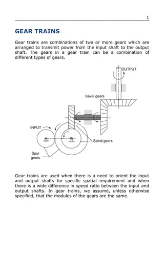
Gear trains are combinations of two or more gears which are
arranged to transmit power from the input shaft to the output
shaft. The gears in a gear train can be a combination of
different types of gears.
OUTPUT
Bevel gears
INPUT
Spiral gears
Spur
gears
Gear trains are used when there is a need to orient the input
and output shafts for specific spatial requirement and when
there is a wide difference in speed ratio between the input and
output shafts. In gear trains, we assume, unless otherwise
specified, that the modules of the gears are the same.
2. 2
Types of Gear Trains
1. Simple gear train
In a simple gear train, there is only one gear per
shaft.
2. Compound gear train
In a compound gear train, there can be more
than one gear per shaft.
3. Epicyclic gear train
Ring gear or
Internal gear
Planet arm
Sun gear
Planet pinions
In an epicyclic gear train, the gears are mounted
in shafts that are moving relative to a fixed axis.
In this gear train, at least one gear axis is on
rotation relative to the frame.
3. 3
SIMPLE GEAR TRAINS
ω3
ω2
ω1
T1 T2 T3
Considering Gear 1 and 2, both rotates at opposite direction:
1 T
2
2 T1
2 T2 1 T1 (1)
Considering Gear 2 and 3, both rotates at opposite direction:
2 3
2 T2 3 T3 (2)
Substitute (1) to (2):
1T1 3T3
4. 4
Hence,
1 T
VR 3
3 T1
We can see that the velocity ratio of between the input and the
output shaft of a simple gear train is independent of the
intermediate gear 2, the intermediate gear will just change the
direction of rotation of gear 3. The positive sign of the velocity
ratio signifies that both the input gear 1 and output gear 2 are
rotating at the same direction.
Different Types of Simple Gear Trains
(a)
1 3
2
1 T
VR 3
3 T1
6. 6
COMPOUND GEAR TRAINS
ω4
ω2
ω1
ω3
T2
T1
T3 T4
Considering Gear 1 and 2, both rotates at opposite direction:
1 T
2
2 T1
2 T2 1 T1 (1)
Considering Gear 2 and 3:
2 3 (2)
Considering Gear 3 and 4, both rotates at opposite direction:
3 T
4
4 T3
4 T4
2 3 (3)
T3
Substitute (3) to (1):
T
4 4
T
T2 1 T1
3
7. 7
Hence,
1 T T
VR 2 4
4 T1 T3
Pr oduct of teeth on driven gears
VR
Pr oduct of teeth on driving gears
For compound gear train, the speed ratio is decided by all the number of teeth in the gear.
MACHINE TOOL GEAR TRAIN APPLICATIONS
A gear box is an enclosed metal casing of gear assembly that is used to generate several
output speed from one input speed, such as in automobiles and machine tools.
T9d
T8c T10e
Upper shifting gear
block
Spindle
T3a T4b T5c T7e
T6d
T1a T2b
Electric Motor Lower shifting gear
block
Figure shows a layout of machine tool spindle with six speeds. In a machine tool gear box,
we use slide cluster to change the engagement of the gears. This is different with
automobile gear boxes because in a machine tool gear boxes, we have to stop first the
machine before we can change the gear engagement.