
Recommandé
Contenu connexe
Tendances
Tendances (20)
En vedette
En vedette (20)
Similaire à Inverters
Similaire à Inverters (20)
Plus de popet
Plus de popet (20)
Dernier
Dernier (20)
Inverters
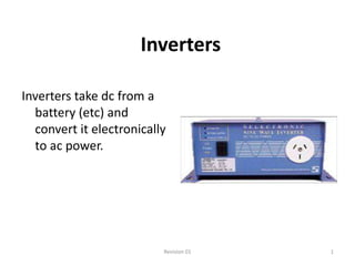
- 1. Inverters Inverters take dc from a battery (etc) and convert it electronically to ac power. Revision 01 1
- 2. Revision 01 2
- 3. Block diagram of and inverter AC Out DC In Switches Transformer Rectifier Filter DC Out DC to AC Output is sampled to adjust switching for voltage regulation Revision 01 3
- 4. Inverter OPERATION • Inverters are classified by their ac output waveform. – Square wave – Modified sine wave – True sine wave Revision 01 4
- 5. Inverter operation Sine Wave Square Wave Modified Square Wave Revision 01 5
- 6. Inverter operation • Most smaller inverters are either square wave (cheap) or modified square wave. Revision 01 6
- 7. Inverter operation By closing and opening the switch rapidly, a square wave supply to the transformer is achieved. This used to be done mechanically with a “vibrator”. (Yeah! I know…) Revision 01 7
- 8. Inverter operation The switches close in turn, producing a pseudo-AC in the primary. Not that rectification is centre-tapped, full wave, with an L filter. Revision 01 8
- 9. Inverter operation Here the rectifier is a full wave, bridge, with L filter. Revision 01 9
- 10. Inverter operation A single winding is used here on the primary, with the switches closing is sequence to provide AC to the primary. Revision 01 10
- 11. Vibrator Vibrator Here is what one looks like. Inside are vibrating mechanical contact points that oscillate and generate a low voltage AC signal from the DC voltage applied to it from the battery. The AC signal then feeds a transformer where the voltage is increased. AC Out Revision 01 11
- 12. Revision 01 12
- 13. Square waves • Cheap • Very poor regulation • Produce large amounts of RFI • Very rough AC • Large amounts of harmonics • Often used for small appliances eg; fluro lights Very few but the very cheapest inverters any more are square wave. A square wave inverter will run simple things like tools with universal motors with no problem - but not much else. These are seldom seen any more except in small, very cheap or very old inverters. Revision 01 13