An experimental investigation into melt pump performance
•
1 j'aime•1,832 vues

This document summarizes an experimental investigation into melt pump performance using three different resins. Key findings include: 1. Melt pump efficiency and output decreased as discharge pressure increased, and efficiency was higher for stiffer resins which experienced less backflow. Stiffer HDPE had the highest efficiency while softer PS had the lowest. 2. Higher discharge pressures and pump speeds increased melt temperature. PP had the highest melt temperatures, followed by HDPE then PS. 3. Stiffer resins and higher pressures led to higher motor amperage requirements. Pump sizing should account for resin properties and system pressure differentials.

Recommandé
Recommandé
Contenu connexe
Tendances
Tendances (20)
Similaire à An experimental investigation into melt pump performance
Similaire à An experimental investigation into melt pump performance (20)
Plus de R&B Plastics Machinery
Plus de R&B Plastics Machinery (20)
Dernier
Dernier (20)
An experimental investigation into melt pump performance
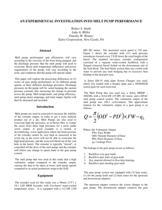
- 1. AN EXPERIMENTAL INVESTIGATION INTO MELT PUMP PERFORMANCE Walter S. Smith Luke A. Miller Timothy W. Womer Xaloy Corporation, New Castle, PA Abstract Melt pump performance and efficiencies will vary according to the viscosity of the resin being pumped, and the discharge pressure that the melt pump will need to overcome. Resin melt temperature differences and power requirements of the pump, will vary according to the resin, and conditions that the pump will operate under. This paper will explore the processing differences in (3) resins on gear pump performance at (4) different pump speeds, at three different discharge pressures. Discharge pressures on the pump will be varied keeping the suction pressure constant, thus increasing the change in pressure across the pump. Melt temperature, and pump efficiency. melt pump motor amperage, and total output, (kg/hr) will then be measured and recorded. Introduction Melt pumps are used in extrusion to increase the stability of the extruder output, in order to get a more uniform product out of a die. Melt Pumps are also used to overcome high die pressures, as in blown film, to isolate the screw from these high pressures for a more stable screw output. A good example is a vented, or devolatilizing, screw application where the head pressure of the extruder cannot be very high as measured at the screw tip, or the screw will not be able to overcome the high head pressure, and the resin will bleed out of the vent hole in the barrel. The extruder is typically “slaved”, or controlled off the drive of the melt pump; and the extruder will follow any change in speed made to the gear pump control. The melt pump that was used in this study had a high volumetric output compared to the extruder output, causing the data to be taken at lower melt pump speeds compared to an actual production setup in the field. Equipment The extruder used for this study was a 90mm (3.5”) x 24:1 L/D NRM Extruder with five-barrel water-cooled temperature zones. It is equipped with a 112 kW (150 HP) DC motor. The maximum screw speed is 129 rpm. Figure 1 shows the extruder with (11) melt pressure transducers located every 2 L/D down the axial length of the barrel. The standard two-piece extruder configuration consisted of a separate water-cooled feedblock with a flanged extrusion barrel bolted on the downstream end of the feed block. The feed block section then was cooled with water to prevent any melt bridging due to excessive heat buildup in the feed port area. A Xaloy EH-35 slide plate Screen Changer was used, which was loaded with a breaker plate and a 20/40/60/20 screen pack for each resin trial. The Melt Pump that was used was a Xaloy MHDP – 300/200, with a 18.64 kW (25 HP) AC motor, and a GPAC melt pump control system. The volumetric output of the melt pump was 186.1 cc/revolution. The approximate relation for the volumetric output of a gear pump is as follows: ( ) LqFWPDODQ −×−= 22 2 π Where: Q= Volumetric Output FW= Face Width OD= Outside Diameter of Gear PD= Pitch Diameter of Gear qL= Leakage Flow The leakage in the gear pump occurs as follows: 1. Backflow over gear lands 2. Backflow past sides of gear teeth 3. Any material allowed to flow thru bearings 4. Backflow past meshing gear teeth The gear pump system was equipped with (3) heat zones, (1) for the pump itself and (2) heat zones for the upstream and downstream adapters. The upstream adapter connects the screen changer to the gear pump. The downstream adapter connects the gear
- 2. pump to the melt valve. Figure 2 shows the melt valve crossection assembly. This was used to vary the downstream pressure of the melt pump for each of the resin trials used in this study. Figure 3 shows the entire component configuration downstream of the barrel. A low shear barrier screw with mixer was used for all testing. This screw was specifically designed as a general purpose extrusion screw. A Fluke Data Acquisition System was used to acquire all data from the process. It will be referred to as NetDAQ. Resins Tested Three virgin resins were used for this study were: • .45 MFR HDPE – Exxon Mobil HD 7845.30 • .65 MFR PP – Chevron Phillips Marlex BF03A • 1.5 MFR PS – Dow Styron 685D Experimental Procedure Each of the three resins were extruded on the same NRM 90mm x 24:1 L/D extruder–screen changer–melt pump– melt valve, configuration for three one minute samples at four different melt pump speeds, at three different melt pump discharge pressures. The suction pressure of the melt pump was set at 69 bar for all trial runs in this study. The discharge pressure of the melt pump was manually varied via the melt valve; to 138 bar, 207 bar, and 276 bar. There were a total of thirty-six trial runs in this study. The approximate relation for the volumetric output of a gear pump is as follows: For each test, the barrel and screw were completely cleaned. The extruder and downstream components were pre-heated to processing temperature for one hour before the testing started. Steady thermal conditions were then assumed to prevail throughout each of the thirty-six trial runs. Chart 1 shows the processing set temperatures for each of the three resins that were processed in this study. Please note that a “hump” type barrel temperature profile was used in each of the resin trial runs in conjunction with the low shear barrier screw design. This type barrel temperature profile does enable this barrier screw design to process these resins more efficiently. Each test included melt pump speeds of 4, 7, 10, and 13 rpm. Melt temperature was checked at each screw rpm using a hand held IR gun, and a pre-heated melt probe at the discharge of the melt valve. Three one-minute output samples were taken, and averaged at each set melt pump rpm to calculate output rate. The screw speed and melt pump motor amps; inlet and outlet pressures to the melt pump, were all monitored and recorded at one-second intervals on the NetDAQ. The data were then extracted from the NetDAQ and compiled with a spreadsheet program. Presentation of Data and Results The results for the .45 MFR HDPE pump trials were as follows: The melt pump output decreased, as the outlet pressure from the pump was increased, by the adjustment of the melt valve that was downstream of the melt pump. See Figure 4, for the outputs in kg/hr across all four pump speeds at the three discharge pressures for HDPE. At a 138 bar outlet pressure, the pump averaged a 97.2% of calculated theoretical output across all four pump speeds. At a 207 bar outlet pressure, the melt pump averaged a 94% of calculated theoretical output across all four pump speeds. At a 276 bar outlet pressure, the melt pump averaged 87% of calculated theoretical output across all the four pump speeds. The discharge HDPE melt temperature was, as expected; greater at higher pump speeds and at higher set outlet pressure across all four pump speeds. See Figure 5, for the HDPE melt temperatures at the four pump speeds, and three set outlet pressures. The average measured HDPE melt temperature for the 138 bar outlet pressure trials was 228 °C. The average melt temperature for the 207 bar outlet pressure trials was 232°C. The average melt temperature for the 276 bar outlet pressure trials was 235°C. The pump motor amps were higher at all three outlet pressures and pump speeds for the .45 MFR HDPE, than the .65 MFR PP, and the 1.5 MFR PS trials, as shown in Figure 10. The calculated pump efficiency was also greater with the stiffer HDPE resin trials, than the PP and PS resin trials, as shown in Figure 11. The results for the .65 MFR PP pump trials were as follows: The melt pump output decreased, as the outlet pressure from the pump was increased, by the adjustment of the melt valve that was downstream of the melt pump. See Figure 6, for the outputs in kg/hr across all four pump speeds at the three discharge pressures for PP. At a 138 bar
- 3. outlet pressure, the pump averaged a 95% of calculated theoretical output across all four pump speeds. At a 207 bar outlet pressure, the melt pump averaged a 91% of calculated theoretical output across all four pump speeds. At a 276 bar outlet pressure, the melt pump averaged 78% of calculated theoretical output across all the four pump speeds. The discharge PP melt temperature was, as expected; greater at higher pump speeds and at higher set outlet pressure across all four pump speeds. See Figure 7, for the PP melt temperatures at the four pump speeds, and three set outlet pressures. The average measured PP melt temperature for the 138 bar outlet pressure trials was 232 °C. The average melt temperature for the 207 bar outlet pressure trials was 234°C. The average melt temperature for the 276 bar outlet pressure trials was 235°C. The pump motor amps were on average higher, at outlet pressures and pump speeds for the .65 MFR PP, than the 1.5 MFR PS trials; but lower than the .45 MFR HDPE resin trials, as shown in Figure 10. The calculated pump efficiency was also greater with the stiffer PP resin than the PS resin trials, but lower than the HDPE trials, as shown in Figure 11. The results for the 1.5 MFR PS pump trials were as follows: The melt pump output decreased, as the outlet pressure from the pump was increased, by the adjustment of the melt valve that was downstream of the melt pump. See Figure 8, for the outputs in kg/hr across all four pump speeds at the three discharge pressures for PS. At a 138 bar outlet pressure, the pump averaged a 94% of calculated theoretical output across all four pump speeds. At a 207 bar outlet pressure, the melt pump averaged a 83% of calculated theoretical output across all four pump speeds. At a 276 bar outlet pressure, the melt pump averaged 70% of calculated theoretical output across all the four pump speeds. The discharge PS melt temperature was, as expected; greater at higher pump speeds and at higher set outlet pressure across all four pump speeds. See Figure 9, for the PS melt temperatures at the four pump speeds, and three set outlet pressures. The average measured PS melt temperature for the 138 bar outlet pressure trials was 226 °C. The average melt temperature for the 207 bar outlet pressure trials was 231°C. The average melt temperature for the 276 bar outlet pressure trials was 232°C. The pump motor amps were lower at all three outlet pressures and pump speeds for the 1.5 MFR PS, than the .45 MFR HDPE trials and the .65 MFR PP resin trials, as shown in Figure 10. The calculated pump efficiency was also lower for the 1.5 MFR PS resin than with the stiffer PP and HDPE resin trials, as shown in Figure 11. Discussion of Data and Results The melt pump efficiency depended on both the stiffness of the resin and the pressure differential, from the inlet side of the pump to the outlet side of the pump. The stiffer the resin, the higher pumping efficiency of the pump was observed. The lower the pressure differential from the inlet side of the pump to the outlet side of the pump, the higher pumping efficiency of the pump was observed. It can be concluded that at the higher pressure differentials from inlet to the outlet side of the pump, the more “backflow” of resin to the lower pressure inlet side of the pump occurs, resulting in a lower pumping efficiency of the pump. It can also be concluded that the stiffer the resin, the less pressure sensitive the pump is to a higher pressure differential and this also resulted higher pump efficiencies. It was also observed that melt pump efficiency was lower at the lower pump speeds than at the higher pump speeds at the same pressure differential running the same resin. It can be concluded that resin pressure flow back towards the inlet side of the pump, was greater part of the overall pumping capacity at lower pump speeds. It was also observed that the higher the pressure differential across the pump, the higher the measured melt temperatures at the discharge of the melt pump were recorded. The .65 MFR PP had the highest measured melt temperatures, then the .45 MFR HDPE, and lastly the 1.5 MFR PS. It was also observed that the higher the pump speed, the higher the measured resin melt temperatures were obtained. Higher melt pump motor amperages were observed for the stiffer resins, and at the higher pressure differentials. Conclusions 1. Melts pumps should be properly sized for the extruder and output requirement of the proposed application. The pump should not be required to run at excessive speeds resulting in high melt temperatures, resulting in excess downstream cooling requirements. 2. Resin rheological “stiffness”, should be taken into account when designing the clearances on a melt pump system, to assured high pump efficiencies, along with adequate pump lubrication. 3. Melt pumps motors should be sized with the highest pressure differential for the application, along with the resin “stiffness”, in order to insure adequate power availability.
- 4. References 1. C. Rauwendaal, Polymer Extrusion, Hanser Publishers, NY, 1986 2. Z. Tadmor and I. Klein, Engineering Principles of Plasticating Extrusion, Reinhold, NY, 1970. 3. C. Chung, Extrusion of Polymers, Hanser Publishers, NY, 2000. 4. F. Henson, Plastics Extrusion Technology, Hanser Publishers, NY, 1997. 5. S.Fox, Mechanical Design and Process Considerations for Polymer Gear Pumps in Extrusion, Normag Corporation. Keywords Volumetric output, melt pump, devolatilizing, NETDAQ Rate of HDPE 0 20 40 60 80 100 120 140 4 7 10 13 Pump Speed (RPM) KG/HR 138 Bar 207 Bar 276 Bar Theo. Rate Melt Temperature of HDPE 100 120 140 160 180 200 220 240 260 4 7 10 13 Pump Speed (RPM) Temperature(°C) 138 Bar 207 Bar 276 Bar Figure 1-90mm x 24:1 NRM Extruder Figure 2- Melt Valve Figure 5- HDPE Melt Temperature Figure 4- HDPE Output Figure 3- Down Stream Equipment Screen Changer Melt Pump Melt Valve
- 5. Rate of PP 0 20 40 60 80 100 120 140 4 7 10 13 Pump Speed (RPM) KG/HR 138 Bar 207 Bar 276 Bar Theo. Rate Melt Temperature of PP 100 120 140 160 180 200 220 240 260 4 7 10 13 Pump Speed (RPM) Temperature(°C) 138 Bar 207 Bar 276 Bar Rate of PS 0 20 40 60 80 100 120 140 4 7 10 13 Pump Speed (RPM) KG/HR 138 Bar 207 Bar 276 Bar Theo. Rate Melt Temperature of PS 100 120 140 160 180 200 220 240 260 4 7 10 13 Pump Speed (RPM) Temperature(°C) 138 Bar 207 Bar 276 Bar Average Pump Amps Vs. Pressure 15.0 15.5 16.0 16.5 17.0 17.5 18.0 18.5 19.0 19.5 138 207 276 Pressure (Bar) Amps HDPE PP PS Pump Efficiency 40% 50% 60% 70% 80% 90% 100% 138 207 276 Pressure (Bar) (%) HDPE PP PS Resin BZ1 BZ2 BZ3 BZ4 BZ5 S/C AD MP AD MV HDPE 190 232 227 221 210 204 204 204 204 204 PP 204 232 227 221 216 210 210 210 210 210 PS 190 218 213 207 204 204 204 204 204 204 Figure 11- Pump Efficiency Figure 7- PP Melt Temperature Figure 8- PS Output Figure 6- PP Output Figure 9- PS Melt Temperature Figure 10- Motor Amps Chart 1-Processing Temperatures (°C)