Solids conveying consistency

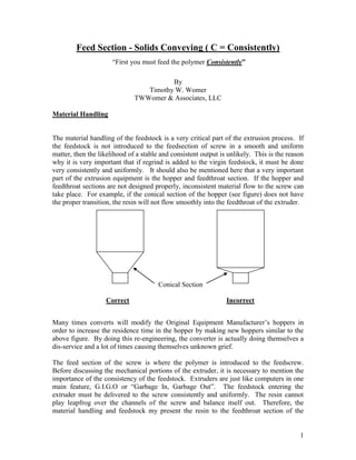
The material handling of the feedstock is a very critical part of the extrusion process. If the feedstock is not introduced to the feedsection of screw in a smooth and uniform matter, then the likelihood of a stable and consistent output is unlikely. This is the reason why it is very important that if regrind is added to the virgin feedstock, it must be done very consistently and uniformly. It should also be mentioned here that a very important part of the extrusion equipment is the hopper and feedthroat section. If the hopper and feedthroat sections are not designed properly, inconsistent material flow to the screw can take place. For example, if the conical section of the hopper (see figure) does not have the proper transition, the resin will not flow smoothly into the feedthroat of the extruder.

Recommandé
Recommandé
Contenu connexe
Tendances
Tendances (11)
Similaire à Solids conveying consistency
Similaire à Solids conveying consistency (20)
Plus de R&B Plastics Machinery
Plus de R&B Plastics Machinery (16)
Dernier
Dernier (20)
Solids conveying consistency
- 1. 1 Feed Section - Solids Conveying ( C = Consistently) “First you must feed the polymer Consistently” By Timothy W. Womer TWWomer & Associates, LLC Material Handling The material handling of the feedstock is a very critical part of the extrusion process. If the feedstock is not introduced to the feedsection of screw in a smooth and uniform matter, then the likelihood of a stable and consistent output is unlikely. This is the reason why it is very important that if regrind is added to the virgin feedstock, it must be done very consistently and uniformly. It should also be mentioned here that a very important part of the extrusion equipment is the hopper and feedthroat section. If the hopper and feedthroat sections are not designed properly, inconsistent material flow to the screw can take place. For example, if the conical section of the hopper (see figure) does not have the proper transition, the resin will not flow smoothly into the feedthroat of the extruder. Many times converts will modify the Original Equipment Manufacturer’s hoppers in order to increase the residence time in the hopper by making new hoppers similar to the above figure. By doing this re-engineering, the converter is actually doing themselves a dis-service and a lot of times causing themselves unknown grief. The feed section of the screw is where the polymer is introduced to the feedscrew. Before discussing the mechanical portions of the extruder, it is necessary to mention the importance of the consistency of the feedstock. Extruders are just like computers in one main feature, G.I.G.O or “Garbage In, Garbage Out”. The feedstock entering the extruder must be delivered to the screw consistently and uniformly. The resin cannot play leapfrog over the channels of the screw and balance itself out. Therefore, the material handling and feedstock my present the resin to the feedthroat section of the Conical Section Correct Incorrect
- 2. 2 extruder precisely. One of the biggest problems in extrusion of polyethylene film, be it blown or cast, the edge trim, off-spec and start material typically has to be feed back into the extruder as some form of regrind. Due to the fact that most of this material has been produced as very thin film, causes this regrind to have a very light bulk density. The bulk density of this regrind can be as low as 2 – 3 lb/ cu. ft. versus its original pellet bulk density of ~30 lb/ cu. ft. This lightness causes most difficult not only in material storage and handling, but also in the area of re-introducing it back into the extruder. Several different methods have been used over the years, such as densification, re-pelletizing, fluff/pellet feeders and side arm extruders. In the case of the smooth bore feedscrew, this is typically the deepest portion of the screw. Also, it might be noted here that since it is the deepest section and closest to the drive end of the feedscrew, it is most liable to torsional breakage. Therefore, when designing the feedscrew it very important to take this into consideration. Sometimes, in the case of very small screws (2” in diameter and smaller) it might be advisable to have the screw manufactured from a steel alloy which has a higher yield strength. A Stainless Steel is a good choice sometimes to help combat this design problem. In the feed section of the screw, the primary function is to forward the polymer. This is where solids conveying takes place. The basic theory of solids conveying is that the polymer must stick to the inside diameter of the barrel or sometimes referred to the barrel wall and slip on the screw root. If this simple phenomenon does not occur then the resin can not be transported down the screw channel. In some cases, if the root of the screw is too hot and the resin melts prematurely onto the root of the screw, then a melt plug is formed and no material at all is conveyed forward. This phenomenon was first investigated by Darnell and Mol and presented to the industry in a technical paper that was presented at the 1960 ANTEC (?). Their theory and approach has been the basis of many studies over the years. Since then many others have also studied the feeding mechanism of single stage screws, such as Chung, Kun, Spalding, Campbell and others. But after many dollars of research with very similar conclusions, one item hasn’t changed and that is, the resin must stick to the barrel wall and slip on the screw in order for the resin to be forward. Sometimes it is possible to enhance the slippage of the resin on the screw root, reduce the coefficient of friction (COF) between the resin and the screw root. This reduction of the coefficient of friction can be done by means of either screw root coatings or screw cooling. As for screw coatings, the most common is chrome plating with other choices being Poly-ond® or Armolloy®, all of these are surface treatments which can be applied to the basic metal of the screw and give a better release between the resin and the screw interface. Another means of improving the coefficient of friction between the resin and the screw interface is screw core cooling. (See Figure 3)
- 3. 3 Internal Screw Cooling Figure 3 Screw Cooling is also a means by which the coefficient of friction may possibly be reduced between the root of the screw in the feed section and some resins. By introducing temperature-controlled water through the core of the screw, heat that has migrated into the core of the screw via convection can be removed. Typically, for this application the core of the screw is gundrilled through the first four to six diameters of the screw. Then once the screw is installed into the extruder, a rotary union with a siphon tube is installed into the screw core. The important part of this application is to be able to monitor the amount of water flow or heat removal is taking place. This can be accomplished by installing an immersion thermometer and flow gauge on the discharge side of the flow schematic. It is also recommended that the water flow be controlled with a water valve on the return side of the flow schematic. By placing the valve on the return side of the flow schematic, this allows the rotary union and screw core always to be filled with water and no chance of cavitation and therefore flashing to steam. Typically it is found that by keeping the water flow through the screw core to an exit temperature of about 100º F to 120º F allows the screw core to remain cool enough to eliminate the possibility of the resin sticking to the steel surface. Basically, this simple cooling system gives the operator another temperature cooling zone on the screw which can be used to improve the feeding mechanism of the screw. It will also make it possible for the temperature profile of the barrel heater to be increased which is higher than typical without the chance of causing a melt block in the feed section of the screw. This process was presented in work that was done by Hyun and Spalding at the 1997 ANTEC (?).