SlideShare a Scribd company logo
1 of 8
Installing and Removing SFP and SFP+ Transceiver Modules
How to Install SFP and SFP+ Transceiver Modules
Required Tools
You will need these tools to install the SFP transceiver module:
1 Wrist strap or other personal grounding device to prevent ESD occurrences.
2 Antistatic mat or antistatic foam to set the transceiver on.
Note: Fiber-optic end-face cleaning tools and inspection equipment. For complete
information on inspecting and cleaning fiber-optic connections, see the white-paper
document at this URL:
http://www.cisco.com/en/US/tech/tk482/tk876/technologies_white_paper09186a0080254
eba.shtml
SFP transceiver modules can have three types of latching devices to secure an SFP
transceiver module in a port socket:
•Figure 1 shows an SFP transceiver module with a Mylar tab latch.
•Figure 2 shows an SFP transceiver module with an actuator button latch.
•Figure 3 shows an SFP transceiver module that has a bail clasp latch.
•Figure 4 shows an SFP+ transceiver module that has a bail clasp latch.
Determine which type of latch your SFP transceiver module uses before following the
installation and removal procedures.
Caution 1 Do not install or remove the SFP transceiver module with fiber-optic cables
still attached to it. Doing so may damage cables, cable connectors, or the optical
interfaces and may interfere with the SFP transceiver module latching properly into its
socket connector. Disconnect all cables before removing or installing an SFP transceiver
module.
Caution 2 The SFP transceiver modules are static sensitive devices. Always use an ESD
wrist strap or similar individual grounding device when handling SFP transceiver modules
or coming in contact with modules.
Figure 1 SFP Transceiver Module with a Mylar Tab Latch

Figure 2 SFP Transceiver Module with an Actuator Button Latch

1
Figure 3 SFP Module with a Bail Clasp Latch

Figure 4 SFP+ Module with a Bail Clasp Latch

To install an SFP transceiver module, follow these steps:
Step 1 Attach an ESD-preventive wrist strap to your wrist and to the ESD ground
connector or a bare metal surface on your chassis.
Step 2 Remove the SFP transceiver module from its protective packaging.
Note Do not remove the optical bore dust plugs until directed to do so later in the
procedure.
Step 3 Check the label on the SFP transceiver module body to verify that you have the
correct model for your network.
Step 4 Find the send (TX) and receive (RX) markings that identify the top side of the SFP
transceiver module.
Note On some SFP transceiver modules, the TX and RX marking might be replaced by
arrowheads pointing from the SFP transceiver module connector (transmit direction or
TX) and toward the connector (receive direction or RX).
2
Step 5 Position the SFP transceiver module in front of the socket opening.
Note Different Cisco devices have different SFP module socket configurations. Your
Cisco device could have either a latch-up or a latch-down orientation. Ensure that you
are installing the SFP transceiver module in the correct orientation for your Cisco device.
For more details, see the hardware installation instructions that came with your Cisco
device.
Step 6 Holding it as shown in Figure 5, insert the SFP into the socket until you feel the
connector latch into place.
Figure 5 Inserting an SFP Transceiver Module into a Module Socket

Step 7 Press the SFP into the slot firmly with your thumb as shown in Figure 6
Note For SFP transceiver modules equipped with an actuator latch, you must press firmly
on both the transceiver faceplate and the actuator button to ensure that the transceiver is
properly latched in the socket.
Figure 6 Latching the SFP

Step 8 To verify that the SFP is seated and latched properly:
a. Grasp the SFP as shown in Figure 10 and try to remove it without releasing the latch.
b. If the SFP can not be removed, it is installed and seated properly. If the SFP can be
removed, reinsert it and press harder with your thumb, repeating if necessary until it is
latched securely into the socket.
3
Figure 7 Verifying SFP Installation

Note For optical SFP transceiver modules, before removing the dust plugs and making
any optical connections, observe the following guidelines:
•Always keep the protective dust plugs on the unplugged fiber-optic cable connectors
and the transceiver optical bores until you are ready to make a connection.
•Always inspect and clean the LC connector end-faces just before making any
connections. See the Tip on this page for a pointer to a fiber-optic inspection and
cleaning white paper.
•Always grasp the LC connector housing to plug or unplug a fiber-optic cable.
Step 9 Remove the dust plugs from the network interface cable LC connectors. Save the
dust plugs for future use.
Step 10 Inspect and clean the LC connector's fiber-optic end-faces. See the following Tip
for a pointer to a fiber-optic inspection and cleaning white paper.
Tip For complete information on inspecting and cleaning fiber-optic connections, see the
white-paper document at this URL:
http://www.cisco.com/en/US/tech/tk482/tk876/technologies_white_paper09186a0080254
eba.shtml
Step 11 Remove the dust plugs from the SFP transceiver module optical bores.
Step 12 Immediately attach the network interface cable LC connector to the SFP
transceiver module.
4
Step 13 To connect 1000BASE-T SFP transceiver modules to a copper network, follow
these substeps:
Caution To comply with GR-1089 intrabuilding lightning immunity requirements, you must
use grounded, shielded, twisted-pair Category 5 cabling.
a. Insert the Category 5 network cable RJ-45 connector into the SFP transceiver module
RJ-45 connector.
Note When connecting to a 1000BASE-T-compatible server, workstation, or router, use
four twisted-pair, straight-through Category 5 cabling for the SFP transceiver module
port. When connecting to a 1000BASE-T-compatible switch or repeater, use four twistedpair, crossover Category 5 cabling.
b. Insert the other end of the network cable into an RJ-45 connector on a 1000BASE-Tcompatible target device.
Step 14 Observe the port status LED:
•The LED turns green when the SFP transceiver module and the target device have an
established link.
•The LED turns amber while the STP feature discovers the network topology and
searches for loops. This process takes about 30 seconds, and then the LED turns green.
•If the LED is off, the target device might not be turned on, there might be a cable
problem, or there might be a problem with the adapter installed in the target device. See
the Troubleshooting section of your switch hardware guide for solutions to cabling
problems.
Step 15 Reconfigure and reboot the target device if necessary.

How to Remove SFP and SFP+ Transceiver Modules
Caution 1: The SFP and SFP+ transceiver modules are static sensitive devices. Always
use an ESD wrist strap or similar individual grounding device when handling the
transceiver modules or coming in contact with modules.
Caution 2: Be careful when removing GLC-GE-100FX SFPs from a WS-C3750G-12S-S
switch. The SFP transceiver module temperature might go over 160°F (70°C) and be too
hot to touch with bare hands.
If you are removing an SFP or SFP+ transceiver module, follow these steps:
5
Step 1 Attach an ESD-preventive wrist strap to your wrist and to the ESD ground
connector or a bare metal surface on your chassis.
Step 2 Disconnect the network fiber-optic cable or network copper cable from the
transceiver module connector. For optical transceiver modules, immediately reinstall the
dust plugs in the transceiver module's optical bores and the fiber-optic cable LC
connectors.
Tip: For reattachment of fiber-optic cables, note which connector plug is send (TX) and
which is receive (RX).
Step 3 Release and remove the transceiver module from the socket connector, as shown
in Figure 1 , Figure 2, Figure 3, or
•If the SFP transceiver module has a Mylar tab latch, pull the tab gently in a slightly
downward direction until the transceiver disengages from the socket connector, and then
pull the SFP transceiver module straight out. Do not twist or pull the Mylar tab because
you could detach it from the SFP transceiver module.
Figure 1 Removing an SFP Transceiver Module Equipped with a Mylar Tab

•If the SFP transceiver module has an actuator button latch, gently press the actuator
button on the front of the SFP transceiver module until it clicks and the latch mechanism
releases the SFP transceiver module from the socket connector. Grasp the actuator
button between your thumb and index finger, and carefully pull the SFP transceiver
module straight from the module slot.
Figure 2 Removing an SFP Transceiver Module Equipped with an Actuator Button Latch

•If the SFP transceiver module has a bail clasp latch, pull the latch out and down to eject
the SFP transceiver module from the socket connector. If the bail clasp latch is
obstructed and you cannot use your index finger to open it, use a small, flat-blade
screwdriver or other long, narrow instrument to open the bail clasp latch. Grasp the SFP
transceiver module between your thumb and index finger, and carefully remove it from
6
the socket.
Figure 3 Removing an SFP Transceiver Module Equipped with a Bail Clasp Latch

•The SFP+ transceiver uses a bail clasp style latch which is slightly different than the bail
clasp latch for the SFP transceiver. The SFP+ transceiver bail clasp has a small tab
protruding down from the bail clasp handle To release the SFP+ bail clasp, push the
small tab up and outwards with your index finger to release the bail clasp. Grasp the
SFP+ transceiver between your thumb and index finger and carefully remove the
transceiver from the socket.
Figure 4 Removing an SFP+ Transceiver Equipped with a Bail Clasp Latch with Tab

7
Step 4 Place the removed transceiver module in an antistatic bag or other protective
environment.
More related:
Cisco router rules of nomenclature
How To Recover Cisco Router Password
The Difference of The Cisco Catalyst 2900 and Cisco Catalyst 1900
More Cisco products and Reviews you can visit: http://www.3anetwork.com/blog

3Anetwork.com is a world leading Cisco networking products wholesaler, we wholesale
original new Cisco networking equipments, including Cisco Catalyst switches, Cisco
routers, Cisco firewalls, Cisco wireless products, Cisco modules and interface cards
products at competitive price and ship to worldwide.
Our website: http://www.3anetwork.com
Telephone: +852-3069-7733
Email: info@3Anetwork.com
Address: 23/F Lucky Plaza, 315-321 Lockhart Road, Wanchai, Hongkong

8

More Related Content

What's hot

Huaweiumtsnodebconfigurationprinciple 161222082051
Huaweiumtsnodebconfigurationprinciple 161222082051Huaweiumtsnodebconfigurationprinciple 161222082051
Huaweiumtsnodebconfigurationprinciple 161222082051moussaCoulibaly22
 
Active optical cable
Active optical cableActive optical cable
Active optical cablecablexa02
 
Como pasar de redes HFC a tecnología RFoG
Como pasar de redes HFC a tecnología RFoGComo pasar de redes HFC a tecnología RFoG
Como pasar de redes HFC a tecnología RFoGCable Servicios S.A.
 
Huawei XPIC Hardware Connection
Huawei XPIC Hardware ConnectionHuawei XPIC Hardware Connection
Huawei XPIC Hardware Connectionibrahimnabil17
 
11.greatway triple playproposal110422
11.greatway triple playproposal11042211.greatway triple playproposal110422
11.greatway triple playproposal110422carlosvicunav
 
Huawei GSM Principles
Huawei GSM PrinciplesHuawei GSM Principles
Huawei GSM PrinciplesAchmad Fauzi
 
Cisco catalyst switch cable, connector, and ac power cord guide
Cisco catalyst switch cable, connector, and ac power cord guideCisco catalyst switch cable, connector, and ac power cord guide
Cisco catalyst switch cable, connector, and ac power cord guideIT Tech
 
Zhone gpon ont_ptcl
Zhone gpon ont_ptclZhone gpon ont_ptcl
Zhone gpon ont_ptclsingobejo
 
American Fibertek SFP-59-40 Data Sheet
American Fibertek SFP-59-40 Data SheetAmerican Fibertek SFP-59-40 Data Sheet
American Fibertek SFP-59-40 Data SheetJMAC Supply
 
Opti x rtn 910950980 hardware description wind
Opti x rtn 910950980 hardware description windOpti x rtn 910950980 hardware description wind
Opti x rtn 910950980 hardware description windnctgayaranga
 
Cisco asr 9000 transceiver modules line card support.
Cisco asr 9000 transceiver modules line card support.Cisco asr 9000 transceiver modules line card support.
Cisco asr 9000 transceiver modules line card support.Amanda Meng
 
Energy Micro RF Catalog
Energy Micro RF CatalogEnergy Micro RF Catalog
Energy Micro RF Catalogifletcher
 
Multiply the capacity of your LAN by 400
Multiply the capacity of your LAN by 400Multiply the capacity of your LAN by 400
Multiply the capacity of your LAN by 400Kourosh Matloubi
 
Huaweigsmgrfuintroduction 141128151840-conversion-gate02
Huaweigsmgrfuintroduction 141128151840-conversion-gate02Huaweigsmgrfuintroduction 141128151840-conversion-gate02
Huaweigsmgrfuintroduction 141128151840-conversion-gate02moussaCoulibaly22
 
Sun Ge9100 Series Olt
Sun Ge9100  Series OltSun Ge9100  Series Olt
Sun Ge9100 Series OltDevain
 
Epon Solutions
Epon SolutionsEpon Solutions
Epon SolutionsDevain
 
Exploring the Huawei HG8010H GPON ONT
Exploring the Huawei HG8010H GPON ONTExploring the Huawei HG8010H GPON ONT
Exploring the Huawei HG8010H GPON ONTMarco d'Itri
 

What's hot (19)

Huaweiumtsnodebconfigurationprinciple 161222082051
Huaweiumtsnodebconfigurationprinciple 161222082051Huaweiumtsnodebconfigurationprinciple 161222082051
Huaweiumtsnodebconfigurationprinciple 161222082051
 
Active optical cable
Active optical cableActive optical cable
Active optical cable
 
Como pasar de redes HFC a tecnología RFoG
Como pasar de redes HFC a tecnología RFoGComo pasar de redes HFC a tecnología RFoG
Como pasar de redes HFC a tecnología RFoG
 
Huawei XPIC Hardware Connection
Huawei XPIC Hardware ConnectionHuawei XPIC Hardware Connection
Huawei XPIC Hardware Connection
 
11.greatway triple playproposal110422
11.greatway triple playproposal11042211.greatway triple playproposal110422
11.greatway triple playproposal110422
 
Huawei GSM Principles
Huawei GSM PrinciplesHuawei GSM Principles
Huawei GSM Principles
 
Cisco catalyst switch cable, connector, and ac power cord guide
Cisco catalyst switch cable, connector, and ac power cord guideCisco catalyst switch cable, connector, and ac power cord guide
Cisco catalyst switch cable, connector, and ac power cord guide
 
Zhone gpon ont_ptcl
Zhone gpon ont_ptclZhone gpon ont_ptcl
Zhone gpon ont_ptcl
 
American Fibertek SFP-59-40 Data Sheet
American Fibertek SFP-59-40 Data SheetAmerican Fibertek SFP-59-40 Data Sheet
American Fibertek SFP-59-40 Data Sheet
 
Pon itu
Pon ituPon itu
Pon itu
 
Opti x rtn 910950980 hardware description wind
Opti x rtn 910950980 hardware description windOpti x rtn 910950980 hardware description wind
Opti x rtn 910950980 hardware description wind
 
Cisco asr 9000 transceiver modules line card support.
Cisco asr 9000 transceiver modules line card support.Cisco asr 9000 transceiver modules line card support.
Cisco asr 9000 transceiver modules line card support.
 
Energy Micro RF Catalog
Energy Micro RF CatalogEnergy Micro RF Catalog
Energy Micro RF Catalog
 
Pon po tm_ae
Pon po tm_aePon po tm_ae
Pon po tm_ae
 
Multiply the capacity of your LAN by 400
Multiply the capacity of your LAN by 400Multiply the capacity of your LAN by 400
Multiply the capacity of your LAN by 400
 
Huaweigsmgrfuintroduction 141128151840-conversion-gate02
Huaweigsmgrfuintroduction 141128151840-conversion-gate02Huaweigsmgrfuintroduction 141128151840-conversion-gate02
Huaweigsmgrfuintroduction 141128151840-conversion-gate02
 
Sun Ge9100 Series Olt
Sun Ge9100  Series OltSun Ge9100  Series Olt
Sun Ge9100 Series Olt
 
Epon Solutions
Epon SolutionsEpon Solutions
Epon Solutions
 
Exploring the Huawei HG8010H GPON ONT
Exploring the Huawei HG8010H GPON ONTExploring the Huawei HG8010H GPON ONT
Exploring the Huawei HG8010H GPON ONT
 

Similar to Installing and removing sfp and sfp+ transceiver modules

How to install remove qsfp+ transceivers and dacaoc cables
How to install remove qsfp+ transceivers and dacaoc cablesHow to install remove qsfp+ transceivers and dacaoc cables
How to install remove qsfp+ transceivers and dacaoc cablesMonica Geller
 
What is a transceiver ii
What is a transceiver iiWhat is a transceiver ii
What is a transceiver iiVanessa Shen
 
Fiber coupler
Fiber couplerFiber coupler
Fiber couplerfibermart
 
Singlemode fiber cables
Singlemode fiber cablesSinglemode fiber cables
Singlemode fiber cablesfibermart
 
519710952-6366-MW-HOP-Installation-Guidelines-Bhartij.pdf
519710952-6366-MW-HOP-Installation-Guidelines-Bhartij.pdf519710952-6366-MW-HOP-Installation-Guidelines-Bhartij.pdf
519710952-6366-MW-HOP-Installation-Guidelines-Bhartij.pdfluckychandel2
 
DWDM-SFP25G-10-C60-T02#131054.pdf
DWDM-SFP25G-10-C60-T02#131054.pdfDWDM-SFP25G-10-C60-T02#131054.pdf
DWDM-SFP25G-10-C60-T02#131054.pdfGLsun Mall
 
dwdm-sfp25g-10km-c60-fiber-optical-transceiver-module-data-sheet-131054.pdf
dwdm-sfp25g-10km-c60-fiber-optical-transceiver-module-data-sheet-131054.pdfdwdm-sfp25g-10km-c60-fiber-optical-transceiver-module-data-sheet-131054.pdf
dwdm-sfp25g-10km-c60-fiber-optical-transceiver-module-data-sheet-131054.pdfGLsun Mall
 
DWDM-SFP25G-10-C61-T02#131055.pdf
DWDM-SFP25G-10-C61-T02#131055.pdfDWDM-SFP25G-10-C61-T02#131055.pdf
DWDM-SFP25G-10-C61-T02#131055.pdfGLsun Mall
 
DWDM-SFP25G-10-C61-T02#131055.pdf
DWDM-SFP25G-10-C61-T02#131055.pdfDWDM-SFP25G-10-C61-T02#131055.pdf
DWDM-SFP25G-10-C61-T02#131055.pdfGLsun Mall
 
dwdm-sfp25g-10km-c61-fiber-optical-transceiver-module-data-sheet-131055.pdf
dwdm-sfp25g-10km-c61-fiber-optical-transceiver-module-data-sheet-131055.pdfdwdm-sfp25g-10km-c61-fiber-optical-transceiver-module-data-sheet-131055.pdf
dwdm-sfp25g-10km-c61-fiber-optical-transceiver-module-data-sheet-131055.pdfGLsun Mall
 
dwdm-sfp25g-10km-c56-fiber-optical-transceiver-module-data-sheet-131050.pdf
dwdm-sfp25g-10km-c56-fiber-optical-transceiver-module-data-sheet-131050.pdfdwdm-sfp25g-10km-c56-fiber-optical-transceiver-module-data-sheet-131050.pdf
dwdm-sfp25g-10km-c56-fiber-optical-transceiver-module-data-sheet-131050.pdfGLsun Mall
 
DWDM-SFP25G-10-C56-T02#131050.pdf
DWDM-SFP25G-10-C56-T02#131050.pdfDWDM-SFP25G-10-C56-T02#131050.pdf
DWDM-SFP25G-10-C56-T02#131050.pdfGLsun Mall
 
dwdm-sfp25g-10km-c46-fiber-optical-transceiver-module-data-sheet-131040.pdf
dwdm-sfp25g-10km-c46-fiber-optical-transceiver-module-data-sheet-131040.pdfdwdm-sfp25g-10km-c46-fiber-optical-transceiver-module-data-sheet-131040.pdf
dwdm-sfp25g-10km-c46-fiber-optical-transceiver-module-data-sheet-131040.pdfGLsun Mall
 
DWDM-SFP25G-10-C46-T02#131040.pdf
DWDM-SFP25G-10-C46-T02#131040.pdfDWDM-SFP25G-10-C46-T02#131040.pdf
DWDM-SFP25G-10-C46-T02#131040.pdfGLsun Mall
 
BlueOptics Bo67jxx640d 10gbase dwdm xfp transceiver c-band 40 km singlemode l...
BlueOptics Bo67jxx640d 10gbase dwdm xfp transceiver c-band 40 km singlemode l...BlueOptics Bo67jxx640d 10gbase dwdm xfp transceiver c-band 40 km singlemode l...
BlueOptics Bo67jxx640d 10gbase dwdm xfp transceiver c-band 40 km singlemode l...CBO GmbH
 
Huawei s3700 cables
Huawei s3700 cablesHuawei s3700 cables
Huawei s3700 cablesHuanetwork
 
BlueOptics Bo67jxx680d 10gbase dwdm xfp transceiver c band 80 km singlemode l...
BlueOptics Bo67jxx680d 10gbase dwdm xfp transceiver c band 80 km singlemode l...BlueOptics Bo67jxx680d 10gbase dwdm xfp transceiver c band 80 km singlemode l...
BlueOptics Bo67jxx680d 10gbase dwdm xfp transceiver c band 80 km singlemode l...CBO GmbH
 
dwdm-sfp25g-10km-c54-fiber-optical-transceiver-module-data-sheet-131048.pdf
dwdm-sfp25g-10km-c54-fiber-optical-transceiver-module-data-sheet-131048.pdfdwdm-sfp25g-10km-c54-fiber-optical-transceiver-module-data-sheet-131048.pdf
dwdm-sfp25g-10km-c54-fiber-optical-transceiver-module-data-sheet-131048.pdfGLsun Mall
 
DWDM-SFP25G-10-C54-T02#131048.pdf
DWDM-SFP25G-10-C54-T02#131048.pdfDWDM-SFP25G-10-C54-T02#131048.pdf
DWDM-SFP25G-10-C54-T02#131048.pdfGLsun Mall
 

Similar to Installing and removing sfp and sfp+ transceiver modules (20)

How to install remove qsfp+ transceivers and dacaoc cables
How to install remove qsfp+ transceivers and dacaoc cablesHow to install remove qsfp+ transceivers and dacaoc cables
How to install remove qsfp+ transceivers and dacaoc cables
 
What is a transceiver ii
What is a transceiver iiWhat is a transceiver ii
What is a transceiver ii
 
Fiber coupler
Fiber couplerFiber coupler
Fiber coupler
 
Singlemode fiber cables
Singlemode fiber cablesSinglemode fiber cables
Singlemode fiber cables
 
transceiver minigbic
transceiver minigbictransceiver minigbic
transceiver minigbic
 
519710952-6366-MW-HOP-Installation-Guidelines-Bhartij.pdf
519710952-6366-MW-HOP-Installation-Guidelines-Bhartij.pdf519710952-6366-MW-HOP-Installation-Guidelines-Bhartij.pdf
519710952-6366-MW-HOP-Installation-Guidelines-Bhartij.pdf
 
DWDM-SFP25G-10-C60-T02#131054.pdf
DWDM-SFP25G-10-C60-T02#131054.pdfDWDM-SFP25G-10-C60-T02#131054.pdf
DWDM-SFP25G-10-C60-T02#131054.pdf
 
dwdm-sfp25g-10km-c60-fiber-optical-transceiver-module-data-sheet-131054.pdf
dwdm-sfp25g-10km-c60-fiber-optical-transceiver-module-data-sheet-131054.pdfdwdm-sfp25g-10km-c60-fiber-optical-transceiver-module-data-sheet-131054.pdf
dwdm-sfp25g-10km-c60-fiber-optical-transceiver-module-data-sheet-131054.pdf
 
DWDM-SFP25G-10-C61-T02#131055.pdf
DWDM-SFP25G-10-C61-T02#131055.pdfDWDM-SFP25G-10-C61-T02#131055.pdf
DWDM-SFP25G-10-C61-T02#131055.pdf
 
DWDM-SFP25G-10-C61-T02#131055.pdf
DWDM-SFP25G-10-C61-T02#131055.pdfDWDM-SFP25G-10-C61-T02#131055.pdf
DWDM-SFP25G-10-C61-T02#131055.pdf
 
dwdm-sfp25g-10km-c61-fiber-optical-transceiver-module-data-sheet-131055.pdf
dwdm-sfp25g-10km-c61-fiber-optical-transceiver-module-data-sheet-131055.pdfdwdm-sfp25g-10km-c61-fiber-optical-transceiver-module-data-sheet-131055.pdf
dwdm-sfp25g-10km-c61-fiber-optical-transceiver-module-data-sheet-131055.pdf
 
dwdm-sfp25g-10km-c56-fiber-optical-transceiver-module-data-sheet-131050.pdf
dwdm-sfp25g-10km-c56-fiber-optical-transceiver-module-data-sheet-131050.pdfdwdm-sfp25g-10km-c56-fiber-optical-transceiver-module-data-sheet-131050.pdf
dwdm-sfp25g-10km-c56-fiber-optical-transceiver-module-data-sheet-131050.pdf
 
DWDM-SFP25G-10-C56-T02#131050.pdf
DWDM-SFP25G-10-C56-T02#131050.pdfDWDM-SFP25G-10-C56-T02#131050.pdf
DWDM-SFP25G-10-C56-T02#131050.pdf
 
dwdm-sfp25g-10km-c46-fiber-optical-transceiver-module-data-sheet-131040.pdf
dwdm-sfp25g-10km-c46-fiber-optical-transceiver-module-data-sheet-131040.pdfdwdm-sfp25g-10km-c46-fiber-optical-transceiver-module-data-sheet-131040.pdf
dwdm-sfp25g-10km-c46-fiber-optical-transceiver-module-data-sheet-131040.pdf
 
DWDM-SFP25G-10-C46-T02#131040.pdf
DWDM-SFP25G-10-C46-T02#131040.pdfDWDM-SFP25G-10-C46-T02#131040.pdf
DWDM-SFP25G-10-C46-T02#131040.pdf
 
BlueOptics Bo67jxx640d 10gbase dwdm xfp transceiver c-band 40 km singlemode l...
BlueOptics Bo67jxx640d 10gbase dwdm xfp transceiver c-band 40 km singlemode l...BlueOptics Bo67jxx640d 10gbase dwdm xfp transceiver c-band 40 km singlemode l...
BlueOptics Bo67jxx640d 10gbase dwdm xfp transceiver c-band 40 km singlemode l...
 
Huawei s3700 cables
Huawei s3700 cablesHuawei s3700 cables
Huawei s3700 cables
 
BlueOptics Bo67jxx680d 10gbase dwdm xfp transceiver c band 80 km singlemode l...
BlueOptics Bo67jxx680d 10gbase dwdm xfp transceiver c band 80 km singlemode l...BlueOptics Bo67jxx680d 10gbase dwdm xfp transceiver c band 80 km singlemode l...
BlueOptics Bo67jxx680d 10gbase dwdm xfp transceiver c band 80 km singlemode l...
 
dwdm-sfp25g-10km-c54-fiber-optical-transceiver-module-data-sheet-131048.pdf
dwdm-sfp25g-10km-c54-fiber-optical-transceiver-module-data-sheet-131048.pdfdwdm-sfp25g-10km-c54-fiber-optical-transceiver-module-data-sheet-131048.pdf
dwdm-sfp25g-10km-c54-fiber-optical-transceiver-module-data-sheet-131048.pdf
 
DWDM-SFP25G-10-C54-T02#131048.pdf
DWDM-SFP25G-10-C54-T02#131048.pdfDWDM-SFP25G-10-C54-T02#131048.pdf
DWDM-SFP25G-10-C54-T02#131048.pdf
 

More from 3Anetwork com

Cisco 3900 and cisco 2900 series routers
Cisco 3900 and cisco 2900 series routersCisco 3900 and cisco 2900 series routers
Cisco 3900 and cisco 2900 series routers3Anetwork com
 
Cisco catalyst 2960 x series
Cisco catalyst 2960 x seriesCisco catalyst 2960 x series
Cisco catalyst 2960 x series3Anetwork com
 
Cisco catalyst 3750 x series switches
Cisco catalyst 3750 x series switchesCisco catalyst 3750 x series switches
Cisco catalyst 3750 x series switches3Anetwork com
 
Cisco switches for small business
Cisco switches for small businessCisco switches for small business
Cisco switches for small business3Anetwork com
 
How to recover the password for cisco 2900 integrated services router
How to recover the password for cisco 2900 integrated services routerHow to recover the password for cisco 2900 integrated services router
How to recover the password for cisco 2900 integrated services router3Anetwork com
 
Cisco 4 and 8-port gigabit ethernet ehwi cs
Cisco 4  and 8-port gigabit ethernet ehwi csCisco 4  and 8-port gigabit ethernet ehwi cs
Cisco 4 and 8-port gigabit ethernet ehwi cs3Anetwork com
 
Configuring the cisco switch with the cli based setup program
Configuring the cisco switch with the cli based setup programConfiguring the cisco switch with the cli based setup program
Configuring the cisco switch with the cli based setup program3Anetwork com
 
Cisco 2960 basic configuration – vlan configuration
Cisco 2960 basic configuration – vlan configurationCisco 2960 basic configuration – vlan configuration
Cisco 2960 basic configuration – vlan configuration3Anetwork com
 
Configuring a Cisco Router as a PPPoE Client for DSL Connectivity
 Configuring a Cisco Router as a PPPoE Client for DSL Connectivity Configuring a Cisco Router as a PPPoE Client for DSL Connectivity
Configuring a Cisco Router as a PPPoE Client for DSL Connectivity3Anetwork com
 
Cisco catalyst 3850 series switches datasheet
Cisco catalyst 3850 series switches datasheetCisco catalyst 3850 series switches datasheet
Cisco catalyst 3850 series switches datasheet3Anetwork com
 
Cisco catalyst 2960 series switches overview
Cisco catalyst 2960 series switches overviewCisco catalyst 2960 series switches overview
Cisco catalyst 2960 series switches overview3Anetwork com
 
Enterprise Network Manager: the Router-On-A-stick
Enterprise Network Manager: the Router-On-A-stickEnterprise Network Manager: the Router-On-A-stick
Enterprise Network Manager: the Router-On-A-stick3Anetwork com
 
Cisco Catalyst 2960-X Datasheet
Cisco Catalyst 2960-X DatasheetCisco Catalyst 2960-X Datasheet
Cisco Catalyst 2960-X Datasheet3Anetwork com
 
How to configure a catalyst 3750 x
How to configure a catalyst 3750 xHow to configure a catalyst 3750 x
How to configure a catalyst 3750 x3Anetwork com
 
Hubs vs switches vs routers
Hubs vs switches vs routersHubs vs switches vs routers
Hubs vs switches vs routers3Anetwork com
 
Dmvpn with configuration example
Dmvpn with configuration exampleDmvpn with configuration example
Dmvpn with configuration example3Anetwork com
 
Cisco unified access from vision to reality
Cisco unified access from vision to realityCisco unified access from vision to reality
Cisco unified access from vision to reality3Anetwork com
 
How to use time domain reflectometer (tdr)
How to use time domain reflectometer (tdr)How to use time domain reflectometer (tdr)
How to use time domain reflectometer (tdr)3Anetwork com
 
Cisco router command configuration overview
Cisco router command configuration overviewCisco router command configuration overview
Cisco router command configuration overview3Anetwork com
 
Cisco switch commands cheat sheet
Cisco switch commands cheat sheetCisco switch commands cheat sheet
Cisco switch commands cheat sheet3Anetwork com
 

More from 3Anetwork com (20)

Cisco 3900 and cisco 2900 series routers
Cisco 3900 and cisco 2900 series routersCisco 3900 and cisco 2900 series routers
Cisco 3900 and cisco 2900 series routers
 
Cisco catalyst 2960 x series
Cisco catalyst 2960 x seriesCisco catalyst 2960 x series
Cisco catalyst 2960 x series
 
Cisco catalyst 3750 x series switches
Cisco catalyst 3750 x series switchesCisco catalyst 3750 x series switches
Cisco catalyst 3750 x series switches
 
Cisco switches for small business
Cisco switches for small businessCisco switches for small business
Cisco switches for small business
 
How to recover the password for cisco 2900 integrated services router
How to recover the password for cisco 2900 integrated services routerHow to recover the password for cisco 2900 integrated services router
How to recover the password for cisco 2900 integrated services router
 
Cisco 4 and 8-port gigabit ethernet ehwi cs
Cisco 4  and 8-port gigabit ethernet ehwi csCisco 4  and 8-port gigabit ethernet ehwi cs
Cisco 4 and 8-port gigabit ethernet ehwi cs
 
Configuring the cisco switch with the cli based setup program
Configuring the cisco switch with the cli based setup programConfiguring the cisco switch with the cli based setup program
Configuring the cisco switch with the cli based setup program
 
Cisco 2960 basic configuration – vlan configuration
Cisco 2960 basic configuration – vlan configurationCisco 2960 basic configuration – vlan configuration
Cisco 2960 basic configuration – vlan configuration
 
Configuring a Cisco Router as a PPPoE Client for DSL Connectivity
 Configuring a Cisco Router as a PPPoE Client for DSL Connectivity Configuring a Cisco Router as a PPPoE Client for DSL Connectivity
Configuring a Cisco Router as a PPPoE Client for DSL Connectivity
 
Cisco catalyst 3850 series switches datasheet
Cisco catalyst 3850 series switches datasheetCisco catalyst 3850 series switches datasheet
Cisco catalyst 3850 series switches datasheet
 
Cisco catalyst 2960 series switches overview
Cisco catalyst 2960 series switches overviewCisco catalyst 2960 series switches overview
Cisco catalyst 2960 series switches overview
 
Enterprise Network Manager: the Router-On-A-stick
Enterprise Network Manager: the Router-On-A-stickEnterprise Network Manager: the Router-On-A-stick
Enterprise Network Manager: the Router-On-A-stick
 
Cisco Catalyst 2960-X Datasheet
Cisco Catalyst 2960-X DatasheetCisco Catalyst 2960-X Datasheet
Cisco Catalyst 2960-X Datasheet
 
How to configure a catalyst 3750 x
How to configure a catalyst 3750 xHow to configure a catalyst 3750 x
How to configure a catalyst 3750 x
 
Hubs vs switches vs routers
Hubs vs switches vs routersHubs vs switches vs routers
Hubs vs switches vs routers
 
Dmvpn with configuration example
Dmvpn with configuration exampleDmvpn with configuration example
Dmvpn with configuration example
 
Cisco unified access from vision to reality
Cisco unified access from vision to realityCisco unified access from vision to reality
Cisco unified access from vision to reality
 
How to use time domain reflectometer (tdr)
How to use time domain reflectometer (tdr)How to use time domain reflectometer (tdr)
How to use time domain reflectometer (tdr)
 
Cisco router command configuration overview
Cisco router command configuration overviewCisco router command configuration overview
Cisco router command configuration overview
 
Cisco switch commands cheat sheet
Cisco switch commands cheat sheetCisco switch commands cheat sheet
Cisco switch commands cheat sheet
 

Installing and removing sfp and sfp+ transceiver modules

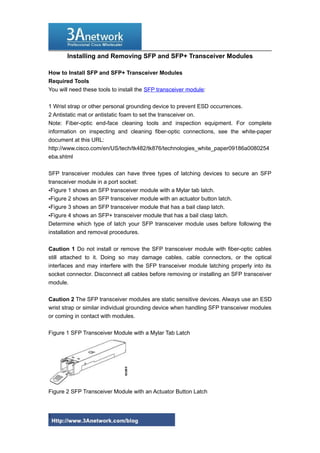
  • 1. Installing and Removing SFP and SFP+ Transceiver Modules How to Install SFP and SFP+ Transceiver Modules Required Tools You will need these tools to install the SFP transceiver module: 1 Wrist strap or other personal grounding device to prevent ESD occurrences. 2 Antistatic mat or antistatic foam to set the transceiver on. Note: Fiber-optic end-face cleaning tools and inspection equipment. For complete information on inspecting and cleaning fiber-optic connections, see the white-paper document at this URL: http://www.cisco.com/en/US/tech/tk482/tk876/technologies_white_paper09186a0080254 eba.shtml SFP transceiver modules can have three types of latching devices to secure an SFP transceiver module in a port socket: •Figure 1 shows an SFP transceiver module with a Mylar tab latch. •Figure 2 shows an SFP transceiver module with an actuator button latch. •Figure 3 shows an SFP transceiver module that has a bail clasp latch. •Figure 4 shows an SFP+ transceiver module that has a bail clasp latch. Determine which type of latch your SFP transceiver module uses before following the installation and removal procedures. Caution 1 Do not install or remove the SFP transceiver module with fiber-optic cables still attached to it. Doing so may damage cables, cable connectors, or the optical interfaces and may interfere with the SFP transceiver module latching properly into its socket connector. Disconnect all cables before removing or installing an SFP transceiver module. Caution 2 The SFP transceiver modules are static sensitive devices. Always use an ESD wrist strap or similar individual grounding device when handling SFP transceiver modules or coming in contact with modules. Figure 1 SFP Transceiver Module with a Mylar Tab Latch Figure 2 SFP Transceiver Module with an Actuator Button Latch 1
  • 2. Figure 3 SFP Module with a Bail Clasp Latch Figure 4 SFP+ Module with a Bail Clasp Latch To install an SFP transceiver module, follow these steps: Step 1 Attach an ESD-preventive wrist strap to your wrist and to the ESD ground connector or a bare metal surface on your chassis. Step 2 Remove the SFP transceiver module from its protective packaging. Note Do not remove the optical bore dust plugs until directed to do so later in the procedure. Step 3 Check the label on the SFP transceiver module body to verify that you have the correct model for your network. Step 4 Find the send (TX) and receive (RX) markings that identify the top side of the SFP transceiver module. Note On some SFP transceiver modules, the TX and RX marking might be replaced by arrowheads pointing from the SFP transceiver module connector (transmit direction or TX) and toward the connector (receive direction or RX). 2
  • 3. Step 5 Position the SFP transceiver module in front of the socket opening. Note Different Cisco devices have different SFP module socket configurations. Your Cisco device could have either a latch-up or a latch-down orientation. Ensure that you are installing the SFP transceiver module in the correct orientation for your Cisco device. For more details, see the hardware installation instructions that came with your Cisco device. Step 6 Holding it as shown in Figure 5, insert the SFP into the socket until you feel the connector latch into place. Figure 5 Inserting an SFP Transceiver Module into a Module Socket Step 7 Press the SFP into the slot firmly with your thumb as shown in Figure 6 Note For SFP transceiver modules equipped with an actuator latch, you must press firmly on both the transceiver faceplate and the actuator button to ensure that the transceiver is properly latched in the socket. Figure 6 Latching the SFP Step 8 To verify that the SFP is seated and latched properly: a. Grasp the SFP as shown in Figure 10 and try to remove it without releasing the latch. b. If the SFP can not be removed, it is installed and seated properly. If the SFP can be removed, reinsert it and press harder with your thumb, repeating if necessary until it is latched securely into the socket. 3
  • 4. Figure 7 Verifying SFP Installation Note For optical SFP transceiver modules, before removing the dust plugs and making any optical connections, observe the following guidelines: •Always keep the protective dust plugs on the unplugged fiber-optic cable connectors and the transceiver optical bores until you are ready to make a connection. •Always inspect and clean the LC connector end-faces just before making any connections. See the Tip on this page for a pointer to a fiber-optic inspection and cleaning white paper. •Always grasp the LC connector housing to plug or unplug a fiber-optic cable. Step 9 Remove the dust plugs from the network interface cable LC connectors. Save the dust plugs for future use. Step 10 Inspect and clean the LC connector's fiber-optic end-faces. See the following Tip for a pointer to a fiber-optic inspection and cleaning white paper. Tip For complete information on inspecting and cleaning fiber-optic connections, see the white-paper document at this URL: http://www.cisco.com/en/US/tech/tk482/tk876/technologies_white_paper09186a0080254 eba.shtml Step 11 Remove the dust plugs from the SFP transceiver module optical bores. Step 12 Immediately attach the network interface cable LC connector to the SFP transceiver module. 4
  • 5. Step 13 To connect 1000BASE-T SFP transceiver modules to a copper network, follow these substeps: Caution To comply with GR-1089 intrabuilding lightning immunity requirements, you must use grounded, shielded, twisted-pair Category 5 cabling. a. Insert the Category 5 network cable RJ-45 connector into the SFP transceiver module RJ-45 connector. Note When connecting to a 1000BASE-T-compatible server, workstation, or router, use four twisted-pair, straight-through Category 5 cabling for the SFP transceiver module port. When connecting to a 1000BASE-T-compatible switch or repeater, use four twistedpair, crossover Category 5 cabling. b. Insert the other end of the network cable into an RJ-45 connector on a 1000BASE-Tcompatible target device. Step 14 Observe the port status LED: •The LED turns green when the SFP transceiver module and the target device have an established link. •The LED turns amber while the STP feature discovers the network topology and searches for loops. This process takes about 30 seconds, and then the LED turns green. •If the LED is off, the target device might not be turned on, there might be a cable problem, or there might be a problem with the adapter installed in the target device. See the Troubleshooting section of your switch hardware guide for solutions to cabling problems. Step 15 Reconfigure and reboot the target device if necessary. How to Remove SFP and SFP+ Transceiver Modules Caution 1: The SFP and SFP+ transceiver modules are static sensitive devices. Always use an ESD wrist strap or similar individual grounding device when handling the transceiver modules or coming in contact with modules. Caution 2: Be careful when removing GLC-GE-100FX SFPs from a WS-C3750G-12S-S switch. The SFP transceiver module temperature might go over 160°F (70°C) and be too hot to touch with bare hands. If you are removing an SFP or SFP+ transceiver module, follow these steps: 5
  • 6. Step 1 Attach an ESD-preventive wrist strap to your wrist and to the ESD ground connector or a bare metal surface on your chassis. Step 2 Disconnect the network fiber-optic cable or network copper cable from the transceiver module connector. For optical transceiver modules, immediately reinstall the dust plugs in the transceiver module's optical bores and the fiber-optic cable LC connectors. Tip: For reattachment of fiber-optic cables, note which connector plug is send (TX) and which is receive (RX). Step 3 Release and remove the transceiver module from the socket connector, as shown in Figure 1 , Figure 2, Figure 3, or •If the SFP transceiver module has a Mylar tab latch, pull the tab gently in a slightly downward direction until the transceiver disengages from the socket connector, and then pull the SFP transceiver module straight out. Do not twist or pull the Mylar tab because you could detach it from the SFP transceiver module. Figure 1 Removing an SFP Transceiver Module Equipped with a Mylar Tab •If the SFP transceiver module has an actuator button latch, gently press the actuator button on the front of the SFP transceiver module until it clicks and the latch mechanism releases the SFP transceiver module from the socket connector. Grasp the actuator button between your thumb and index finger, and carefully pull the SFP transceiver module straight from the module slot. Figure 2 Removing an SFP Transceiver Module Equipped with an Actuator Button Latch •If the SFP transceiver module has a bail clasp latch, pull the latch out and down to eject the SFP transceiver module from the socket connector. If the bail clasp latch is obstructed and you cannot use your index finger to open it, use a small, flat-blade screwdriver or other long, narrow instrument to open the bail clasp latch. Grasp the SFP transceiver module between your thumb and index finger, and carefully remove it from 6
  • 7. the socket. Figure 3 Removing an SFP Transceiver Module Equipped with a Bail Clasp Latch •The SFP+ transceiver uses a bail clasp style latch which is slightly different than the bail clasp latch for the SFP transceiver. The SFP+ transceiver bail clasp has a small tab protruding down from the bail clasp handle To release the SFP+ bail clasp, push the small tab up and outwards with your index finger to release the bail clasp. Grasp the SFP+ transceiver between your thumb and index finger and carefully remove the transceiver from the socket. Figure 4 Removing an SFP+ Transceiver Equipped with a Bail Clasp Latch with Tab 7
  • 8. Step 4 Place the removed transceiver module in an antistatic bag or other protective environment. More related: Cisco router rules of nomenclature How To Recover Cisco Router Password The Difference of The Cisco Catalyst 2900 and Cisco Catalyst 1900 More Cisco products and Reviews you can visit: http://www.3anetwork.com/blog 3Anetwork.com is a world leading Cisco networking products wholesaler, we wholesale original new Cisco networking equipments, including Cisco Catalyst switches, Cisco routers, Cisco firewalls, Cisco wireless products, Cisco modules and interface cards products at competitive price and ship to worldwide. Our website: http://www.3anetwork.com Telephone: +852-3069-7733 Email: info@3Anetwork.com Address: 23/F Lucky Plaza, 315-321 Lockhart Road, Wanchai, Hongkong 8